We propose a simple gradation representation method using a binary-weighted computer-generated hologram (CGH) to be displayed on a high-speed spatial light modulator that can be controlled by the pulse-width modulation technique. The proposed method uses multiple bit planes comprising binary-weighted CGHs with various pulse widths. The object points of a three-dimensional (3D) object are assigned to multiple bit planes according to their gray levels. The bit planes are sequentially displayed in a time-division-multiplexed manner. Consequently, the proposed method realizes a gradation representation of a reconstructed 3D object.
Holography[1] is the only technology that can directly record and reconstruct a three-dimensional (3D) image. A computer-generated hologram (CGH)[2] is a holographic interference pattern obtained by calculating the light propagated from a 3D object using a computer. Electroholography based on CGHs has the potential to enable advanced 3D televisions[3–6].
Digital micromirror devices (DMDs) are high-speed spatial light modulators based on micro-electronic mechanical systems. Studies on gradation representation for electroholography using DMD have been reported[7,8]. The gradation representation methods for DMD use the time-multiplexing technique based on multiple bit planes; the gradation of the reconstructed 3D image can be represented by controlling either the intensity of the reference light[7] or the display time[8]. Here, these quantities are proportional to gray levels in the th bit plane. The former method requires a control system for the reference light, and the latter method cannot satisfactorily express the gradation of the reconstructed image.
In in-line holography, the light intensity of a point on the hologram obtained from a 3D point-cloud model is calculated using the following equation[9]: where () is the light intensity of the point () on the hologram, () is the coordinate of the th point on the 3D object, is the amplitude of the object point, is the number of object points of the 3D model, and is the wavelength of the reference light. Equation (1) is obtained using the Fresnel approximation. After the calculation of Eq. (1), the light intensity of each point on the hologram is binarized using a threshold value of zero[10]. The binary CGH, which is drawn in black and white, is generated from the binarized light intensity of each point on the CGH.
Sign up for Chinese Optics Letters TOC. Get the latest issue of Chinese Optics Letters delivered right to you!Sign up now
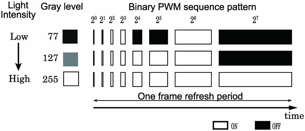
Figure 1 shows the light intensities from the DMD using binary pulse-width modulation (PWM)[11,12]. Binary PWM is used to provide a gray level proportional to the percentage of time when the mirror is “on” during the one-frame-refresh period. As shown in Fig. 1, a total of 256 different binary PWM-sequence on/off patterns is available, corresponding to gray levels of 0 to 255.
Figure 1.Binary PWM-sequence pattern with three examples of how light intensities have different gray levels.
In this Letter, we propose a gradation representation method using binary-weighted CGH for DMD. Figure 2 shows the difference between the binary-weighted CGH and the conventional binary CGH. In Fig. 2 (left), the conventional binary CGH, which is a zone plate of an object point generated by Eq. (1), is drawn in black and white. Here, the amplitude of an object point in Eq. (1) is equal to 1.0. Figure 2 (right) shows a binary-weighted CGH generated by changing the white in the conventional binary CGH to gray. The binary-weighted CGH expressed in 256 gradations can be displayed on a DMD, as shown in Fig. 1. Figure 3 shows the reconstructed object points from the binary-weighted CGHs displayed on DMDs. Here, object point is reconstructed from the conventional binary CGH, and object points and are reconstructed from the binary-weighted CGHs with different gray levels. The light intensity of object point is the highest, while that of object point is higher than that of object point . The higher gray level of a binary-weighted CGH results in a higher light intensity of the reconstructed object point.
Figure 2.(left) Conventional binary CGH and (right) binary-weighted CGH.
Figure 4 shows an outline of the proposed gradation representation method in the case of eight gradations. In Fig. 4, the eight object points with gray levels ranging from zero to seven are assigned to the multiple bit planes , , and . The th bit plane is described by , and the reconstructed object points from bit plane have gray levels. Therefore, the reconstructed object points from the bit planes , , and have , , and gray levels, respectively. In the proposed gradation representation method, a binary-weighted CGH is used as the bit plane. For example, object point with a gray level of five, which is equal to the sum of and , is assigned to the bit planes and , as shown in Fig. 4.
Figure 4.Assignment of the object points of the 3D object to the bit planes consisting of binary-weighted CGHs with different gray levels.
The proposed method for the gradation representation proceeds as follows: The object points of a 3D object are assigned to multiple bit planes depending on their gray levels.In each bit plane, the binary CGH is obtained from the coordinate data of the object points assigned in Step 1 using Eq. (1). Here, the parameter of Eq. (1) is set to 1.0.The binary-weighted CGH is generated by changing the white in the calculated binary CGH from Step 2 to gray and used as bit plane.As shown in Fig. 5, all bit planes are repeatedly displayed on the DMD at a regular time interval of , and the 3D-gradation image is reconstructed.
Figure 5.Gradation object points reconstructed from multiple bit planes using the time-division display.
In Step 3, the gray level of the gray area of the th bit plane is obtained from experiments in advance.
We evaluated the proposed gradation method using the optical setup shown in Fig. 6. In this setup, we used a laser light with a wavelength of 642 nm as a reference light, digital light processing (DLP) LightCrafter 6500 (Texas Instruments, micromirror pixel pitch: 7.6 μm, micromirror array size: )[11] as a DMD system, and a personal computer (PC) equipped with an Intel Core i7 4770 (Clock Speed: 3.4 GHz, quad-core), Linux (CentOS 7.1) as its operating system, the NVIDIA GeForce GTX TITAN X as the graphics processing unit (GPU), and the CUDA 7.0 software-development kit for the GPU programming. The reconstructed real images from binary-weighted CGHs were obtained from a digital camera (Canon EOS 6D) with a 35 mm complementary metal-oxide-semiconductor (CMOS) image sensor and no lens, as shown in Fig. 6. Here, the camera’s image sensor is placed at the position at which the real image reconstructed from the CGH is generated.
Figure 6.Optical setup for the measurement of the light intensity of the reconstructed real image from a binary-weighted CGH.
Figure 7 shows the reproduction of the three bit planes in video mode for the red-green-blue (RGB) colors using the DMD system when the planes are used for the eight-gradation representation. In video mode, the DMD system takes input 24 bit RGB data at a 120 Hz refresh rate. The one-frame-refresh period is composed of the RGB colors. Each display time of an RGB color (, , ) is equal to 2.77 ms. The bit planes can be equally displayed in the one-frame-refresh period when the bit planes are assigned to the RGB colors shown in Fig. 7, respectively.
Figure 7.Reproduction of bit planes in video mode for the RGB colors using the DMD system.
Figure 8 shows how the bit planes are simply assigned to the RGB colors in the video mode of the DMD system. In Fig. 8, we assume that the binary-weighted CGHs corresponding to the bit planes have gray levels of 32, 64, and 128, respectively. The binary-weighted CGHs, which are expressed in 256 gradations, corresponding to the bit planes can be converted to RGB-colored CGHs with an 8 bit depth because the color of the image reconstructed from the binary-weighted CGH depends upon the reference light used in the optical setup shown in Fig. 6. Here, one-colored light is used as reference light. The converted RGB CGHs are composited to a 24 bit color image. The color image is output from the GPU and fed into the DMD system via the DisplayPort. After the DMD system processes the color image, the DMD automatically displays the bit planes , as shown in Fig. 7.
Figure 8.Simple assignment of three bit planes in the video mode of the DMD system.
Figures 9(a) to 9(g) show real images that respectively correspond to gray levels 1 to 7 in Fig. 4, as reconstructed from the bit planes . Here, the distance between the 3D object and the bit planes is 1.0 m. The gray levels of the binary-weighted CGHs corresponding to the bit planes are set to 70, 153, and 223, respectively, such that the gray levels of the real images obtained from digital camera shown in Fig. 6 can be 32, 64, and 128, respectively.
Figure 9.Reconstructed real images corresponding to gray levels one to seven in Fig. 4 when the grayscale values of the binary-weighted CGHs corresponding to the bit planes are respectively set to 70, 153, and 223.
Figure 10 shows the average light intensities of the 49 object points shown in Figs. 9(a) to 9(g). In Fig. 10, the red line and the dots indicate the ideal and measured values of the light intensities of the reconstructed real images with gray levels of one to seven, respectively.
Figure 10.Average light intensities of the 49 object points shown in Figs. 9(a) to 9(g) with grayness levels one to seven in Fig. 4.
Figure 11 (left) shows the vertices of the “Stanford bunny” without hidden surfaces. The 3D model shown in Fig. 11 (left) comprises 12,684 object points. Figure 11 (right) shows the 3D model used in the optical experiment to evaluate the proposed method. In Fig. 11 (right), the depths of the object points, which constitute the vertices of the 3D model shown in Fig. 11 (left), are expressed in eight gradations. In the proposed method, 7419, 7020, and 7020 object points are assigned to the bit planes , , and , respectively.
Figure 11.Original 3D model. (left) The vertices of the “Stanford bunny” without the object points on the hidden surface. (right) Original 3D model with gradation.
Figure 12 shows the optical setup for the reconstructed 3D image. In evaluating the proposed method, the reconstructed 3D images were photographed using a digital camera (Canon EOS 6D) with a lens of which the aperture is F4.0. Figure 13 shows the reconstructed 3D images using the proposed method. In Fig. 13 (left), the grayscale values of the bit planes are 35, 65, and 110, respectively. In Fig. 13 (center), the grayscale values of the bit planes are 60, 110, and 170, respectively. In Fig. 13 (right), the grayscale values of the bit planes are 90, 150, and 255, respectively. Here, the distance between the 3D object and the bit planes is 1.0 m. The reconstructed 3D images shown in Fig. 13 are expressed in gradations. The reconstructed 3D image in Fig. 13 (right) is the brightest of the images shown in Fig. 13.
Figure 12.Optical setup for evaluating the reconstructed 3D image using the proposed method.
Figure 13.Reconstructed real images using the proposed method. (left) The grayscale values of the bit planes , , and are 35, 65, and 110, respectively. (center) The grayscale values of the bit planes , , and are 60, 110, and 170, respectively. (right) The grayscale values of the bit planes , , and are 90, 150, and 255, respectively.
In conclusion, the proposed method achieves a gradation representation of the reconstructed 3D image obtained from a 3D object with gradation using a DMD system. Furthermore, the proposed method can control the light intensity of the reconstructed 3D images with gradation without controlling the brightness of the reference light.