• Photonics Research
  • Vol. 9, Issue 9, 1871 (2021)
Chao Li, Xianyi Cao, Kan Wu*, Gaofeng Qiu, Minglu Cai, Guangjin Zhang, Xinwan Li, and Jianping Chen
Author Affiliations
  • State Key Laboratory of Advanced Optical Communication Systems and Networks, Department of Electronic Engineering, Shanghai Jiao Tong University, Shanghai 200240, China
  • show less
    DOI: 10.1364/PRJ.424393 Cite this Article Set citation alerts
    Chao Li, Xianyi Cao, Kan Wu, Gaofeng Qiu, Minglu Cai, Guangjin Zhang, Xinwan Li, Jianping Chen. Blind zone-suppressed hybrid beam steering for solid-state Lidar[J]. Photonics Research, 2021, 9(9): 1871 Copy Citation Text show less
    Schematic illustration of cylindrical lens-based beam-steering device. Inset: Cross-section of (i) thermal switch and (ii) staircase grating.
    Fig. 1. Schematic illustration of cylindrical lens-based beam-steering device. Inset: Cross-section of (i) thermal switch and (ii) staircase grating.
    Principle of beam steering in (a) xoz plane and (b) yoz plane.
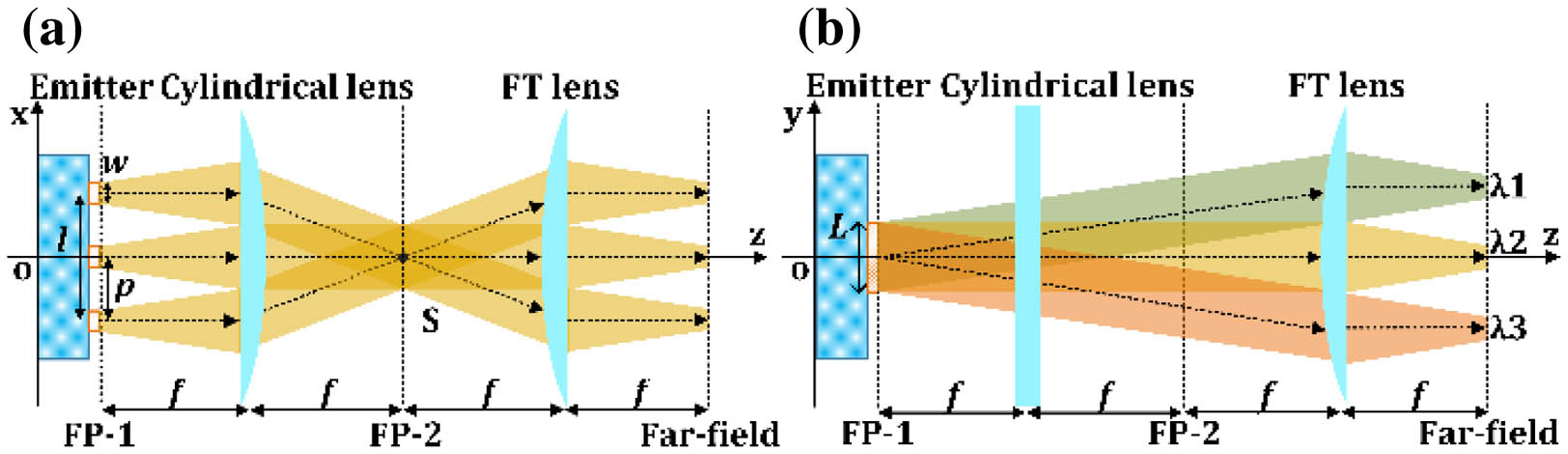
    Fig. 2. Principle of beam steering in (a) xoz plane and (b) yoz plane.
    (a) Photograph of the chip with switch and emitter array. Inset: Radiation intensity of staircase grating captured by an infrared camera. (b) Photograph of the beam-steering device. (c) Speed measurement of the thermo-optical switch. (d) SEM image of the staircase grating. Inset: Zoom-in image. (e) Comparison of radiation intensity between staircase and normal gratings.
    Fig. 3. (a) Photograph of the chip with switch and emitter array. Inset: Radiation intensity of staircase grating captured by an infrared camera. (b) Photograph of the beam-steering device. (c) Speed measurement of the thermo-optical switch. (d) SEM image of the staircase grating. Inset: Zoom-in image. (e) Comparison of radiation intensity between staircase and normal gratings.
    (a) Experimental setup for far-field measurement of grating. (b) Far-field beam pattern of grating with wavelength range of 110 nm. (c) Experimental setup for far-field measurement of LABS device. (d) Far-field beam-steering pattern by emitter selecting and wavelength tuning. (e) Typical transmission spectrum of a 1×2 MZI switch with unequal arms (upper panel) and cross-sectional powers of beam pattern along θ direction at 1550 nm (lower panel). (f) Cross-sectional powers and fitted results of far-field beam pattern from grating (upper panel) and LABS device (lower panel). Inset: Single beam patterns from (b) and (d). (g) Experimental setup for direct measurement of far-field beam patterns from LABS device. (h) Beam-steering patterns by wavelength tuning. (i) Beam-steering patterns by LABS. (j) Beam-steering patterns by LABS in Zemax simulation.
    Fig. 4. (a) Experimental setup for far-field measurement of grating. (b) Far-field beam pattern of grating with wavelength range of 110 nm. (c) Experimental setup for far-field measurement of LABS device. (d) Far-field beam-steering pattern by emitter selecting and wavelength tuning. (e) Typical transmission spectrum of a 1×2 MZI switch with unequal arms (upper panel) and cross-sectional powers of beam pattern along θ direction at 1550 nm (lower panel). (f) Cross-sectional powers and fitted results of far-field beam pattern from grating (upper panel) and LABS device (lower panel). Inset: Single beam patterns from (b) and (d). (g) Experimental setup for direct measurement of far-field beam patterns from LABS device. (h) Beam-steering patterns by wavelength tuning. (i) Beam-steering patterns by LABS. (j) Beam-steering patterns by LABS in Zemax simulation.
    Crosstalk between two grating emitters with different gaps. Inset: Simulated mode distribution from a finite-difference-eigenmode (FDE) solver.
    Fig. 5. Crosstalk between two grating emitters with different gaps. Inset: Simulated mode distribution from a finite-difference-eigenmode (FDE) solver.
    Near-field beam pattern with one grating lit up in grating emitter array with gaps of (a) 1.5 μm and (b) 0.6 μm. Near-field beam pattern with all gratings lit up with gaps of (c) 1.5 μm and (d) 0.6 μm.
    Fig. 6. Near-field beam pattern with one grating lit up in grating emitter array with gaps of (a) 1.5 μm and (b) 0.6 μm. Near-field beam pattern with all gratings lit up with gaps of (c) 1.5 μm and (d) 0.6 μm.
    Far-field beam-steering pattern realized by (a) 16-channel 0.6 μm gap emitters selecting and wavelength tuning, (b) wavelength sweep, and (c) 16-channel emitters selecting.
    Fig. 7. Far-field beam-steering pattern realized by (a) 16-channel 0.6 μm gap emitters selecting and wavelength tuning, (b) wavelength sweep, and (c) 16-channel emitters selecting.
    Experimental setup of target detection with the beam-steering device. Inset: Output spectra and waveforms of (i) pulsed laser, (ii) pulse picker, and (iii) spectral filter.
    Fig. 8. Experimental setup of target detection with the beam-steering device. Inset: Output spectra and waveforms of (i) pulsed laser, (ii) pulse picker, and (iii) spectral filter.
    Picture of experimental setup of Lidar. Inset: Picture of LABS chip with electrical control.
    Fig. 9. Picture of experimental setup of Lidar. Inset: Picture of LABS chip with electrical control.
    (a) Optical spectrum of the light source. (b) Waveforms of reference signal and two returning signals scattered by the targets at 1.08 and 11.22 m.
    Fig. 10. (a) Optical spectrum of the light source. (b) Waveforms of reference signal and two returning signals scattered by the targets at 1.08 and 11.22 m.
    Waveforms of returning signals from different directions along (a) emitter channels of 1, 4, 8, 12, and 16 and (b) wavelength channels from 1541 to 1561 nm.
    Fig. 11. Waveforms of returning signals from different directions along (a) emitter channels of 1, 4, 8, 12, and 16 and (b) wavelength channels from 1541 to 1561 nm.
    (a) Time delays of returning pulses with respect to target distance in three measurements from eighth emitter channel at 1550 nm. (b) Ranging results comparison between beam-steering devices with 121 and 0.6 μm spacing grating array. Inset: Zoomed view of ranging results of the device with 0.6 μm spacing grating array.
    Fig. 12. (a) Time delays of returning pulses with respect to target distance in three measurements from eighth emitter channel at 1550 nm. (b) Ranging results comparison between beam-steering devices with 121 and 0.6 μm spacing grating array. Inset: Zoomed view of ranging results of the device with 0.6 μm spacing grating array.
    Experiment setup of FMCW Lidar system based on LABS.
    Fig. 13. Experiment setup of FMCW Lidar system based on LABS.
    Waveforms of beating signal from targets of (a) 0.3 m, (b) 0.6 m, and (c) 1 m. (d) Electrical spectra of beating frequencies from three targets. (e) Range of targets with respect to beating frequency.
    Fig. 14. Waveforms of beating signal from targets of (a) 0.3 m, (b) 0.6 m, and (c) 1 m. (d) Electrical spectra of beating frequencies from three targets. (e) Range of targets with respect to beating frequency.
    ReferenceStructureBeam QualityBlind ZoneMain Loss (Value)Scanning Method
    [1]Planar lens + 1D gratingAberration>50%a-Si lens (NA)Thermo-optic switch + wavelength tuning
    [8]Prism lens + 1D PCW gratingNA87.5%PCW (10–30 dB/cm)Thermo-optic switch + wavelength tuning
    Our workCylindrical lens + 1D grating25 dB background suppression5%Grating (1–3 dB/cm)Thermo-optic switch + flash emitting
    Table 1. Performance Comparison of Hybrid LABS Devices
    ReferenceBeam Steering Tech.Ranging Tech.Theoretical Max BZSSpeed (μs/point)MaterialControl ComplexityFOVDimensionResolution
    [37]OPA with TO phase shiftersFMCW30SiO(N) analog control56°×15°2D200
    [30]LABS with TO switchesFMCW50% only for 1DNASiO(log2N) digital control70°1D8
    [10]LABS with MEMS switches/emittersTOF<10%4SiN + SiO(1) digital control1°×1°2D100
    [9]LABS with TO switchesTOF50%1000SiO2O(log2N) digital control1°×1°2D16
    This workLABS with TO switchesTOF95%/8.3%a4.2SiNO(log2N) digital control0.91°×8.1°/11.3°×8.1°a2D192
    Table 2. Performance Comparison of Solid-State Lidars with Different Beam Steering and Ranging Technologies
    Chao Li, Xianyi Cao, Kan Wu, Gaofeng Qiu, Minglu Cai, Guangjin Zhang, Xinwan Li, Jianping Chen. Blind zone-suppressed hybrid beam steering for solid-state Lidar[J]. Photonics Research, 2021, 9(9): 1871
    Download Citation