Kun Xie, Wenguang Liu, Qiong Zhou, Zongfu Jiang, Fengjie Xi, Xiaojun Xu, "Real-time phase measurement and correction of dynamic multimode beam using a single spatial light modulator," Chin. Opt. Lett. 18, 011404 (2020)
Copy Citation Text
In this Letter, a novel system for adaptively correcting the phase of a dynamic multimode beam is proposed. While using merely one spatial light modulator, the phase measurement of the first-order diffraction pattern and the correction of the zeroth diffraction order are simultaneously realized. The real-time experimental result is obtained at a control rate of 10 Hz. The power-in-the-bucket value is improved from 38.5% to 61.8%, even with fundamental mode content that is consistently below 30%. To the best of our knowledge, this is the first implementation of real-time adaptive correction of the entire multimode beam.
Fiber lasers and amplifiers have undergone rapid development in recent decades because of their exceptional thermal management, high conversion efficiency, and good flexibility, which are desirable properties for many applications in industrial processing and medical treatment[1,2]. Although the kilowatt-level output power has been realized with near-diffraction-limitation[3,4], the rising power density in the active fiber core will inevitably lead to detrimental nonlinear effects, which limits further power scalability[5,6]. To circumvent this effect, the mode-field area should be enlarged. The conventional approach of using large-mode-area (LMA) fiber increases the number of supported transverse modes and causes the propagation of higher-order modes (HOMs), which generally degrade the output beam quality[7]. Furthermore, in high-power operation, transverse mode instabilities (TMIs) will potentially emerge. The onset of this effect is typically concurrent with dynamic mode coupling between the fundamental mode (FM) and HOM(s), which leads to severe degradation of beam quality[8–12].
To increase the mode area of the active fiber while maintaining FM purity at the same time, significant research effort has been applied to extreme fiber designs[13–18]. However, the sophisticated inner structures of these fibers are difficult to manufacture; more importantly, part of the gain abstraction is wasted with the loss of HOMs.
Compared with a complicated internal structure design, the adaptive optics (AO) technique opens a new approach without redesigning the fiber. By correcting the phase of the multimode (MM) output beam, the beam quality can be preserved even in high-power operation while simultaneously maximizing the gain potential of the fiber. This technique was first applied in high-power solid-state lasers and achieved phase correction by using deformable mirrors (DMs)[19,20]. Then, it was adapted to fiber laser systems to correct the phase of an MM beam based on the iterative optimization algorithm[21–24]. However, the convergence time of this algorithm could exceed several minutes; thus, only static corrections were possible. For real-time correction, in which a rapid phase measurement is correspondingly required, a phase-conjugation-based AO system without iteration must be used. The well-known modal decomposition (MD) technique, which can determine the mode component in real-time, has shown capability in this regard[25,26]. It has been proved that the phase of an MM beam can be reconstructed by MD with good accuracy[27,28]. However, the study of dynamic phase correction by MD is still lacking.
Sign up for Chinese Optics Letters TOC. Get the latest issue of Chinese Optics Letters delivered right to you!Sign up now
Recently, a demonstrative experiment on adaptive phase correction of a dynamic MM beam based on MD was presented[29], which verified its feasibility for real-time correction. However, the measurement and correction in this demonstration were aimed at the -order diffraction pattern of a spatial light modulator (SLM). This order only accounts for a small fraction of the total power, and the pertinent method[29] cannot correct the entire MM optical field. To further realize correction of the zeroth order, which holds the majority of the total power, an additional phase corrector, such as a DM or SLM, is conventionally introduced. Nevertheless, the optical path needs to be carefully designed and adjusted for this configuration, which will not only significantly increase the system complexity but also unavoidably induce optical axis errors.
In this Letter, a novel system for simultaneously realizing real-time phase measurement and correction of the zeroth-order with only one SLM is proposed. This system is validated through experimentation. The pertinent study provides a systematic implementation of phase correction for the dynamic MM beam, which has great application significance in solving the beam quality degradation in high-power fiber lasers.
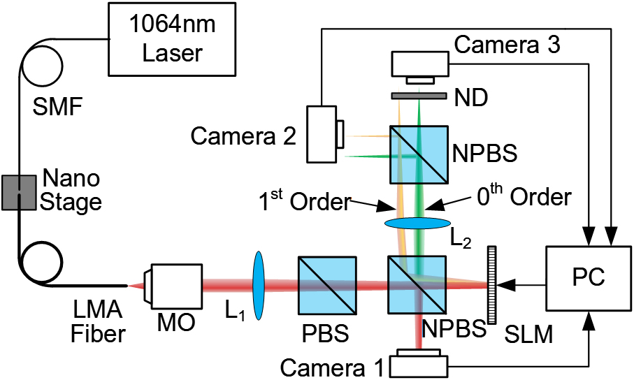
The experimental setup for phase measurement and correction is shown in Fig. 1. A single-mode fiber (SMF) pigtailed single-frequency fiber laser () is coupled into a step-index LMA fiber with a core diameter of 25 μm, a core NA of 0.065, and a fiber length of 2 m. At the operation wavelength of 1064 nm, this LMA fiber supports six eigenmodes: , , , , , and . The coupling condition of these two fibers can be changed by moving the output end of the SMF with a nano-position stage, and different MM beams could be excited in the LMA fiber. A ‐ system constructed by a microscopic objective (MO, 40×) and an achromatic lens (L1, whose focal length is 500 mm) is then used to expand the output beam from the LMA fiber. A polarizing beam splitter (PBS) is placed after L1 to select the polarization component of the beam to match the working direction of the SLM. Through a non-PBS (NPBS), the expanded output beam from the PBS is split into two beams that are separately incident on a phase-only SLM (Meadowlark, HSP1920, 9.2 μm pixel pitch) and a near-field camera (Camera 1, Pointgrey, BFLY-U3-23S6M, 5.86 μm pixel pitch). Camera 1 is used to capture the near-field intensity distribution of the incident field. The key component SLM, which can display a computer-generated hologram (CGH), is used to decompose the mode and then correct the phase. The MM beam incident on the SLM is diffracted by the CGH and then divided into three diffraction orders. The phase measurement and correction are separately yet simultaneously performed in different orders. In the zeroth diffraction order, the phase of the incident MM beam is corrected to be a plane (green beam in Fig. 1). This order accounts for 96.8% of the total power. Next, the order (orange beam in Fig. 1) and the order (mirror of the order and not shown in Fig. 1) each account for only 1.61% of the total power but carry information of the mode component. These diffraction orders are then Fourier transformed by L2 and split by another NPBS.
Figure 1.Experiment setup for the proposed MD and phase correction system.
Because the diffraction pattern in the zeroth order is much brighter than that in the order, it is acquired by two separate cameras placed after the NPBS. Camera 2 (Pointgrey, CM3-U3-31S4M, 3.45 μm pixel pitch) captures the -order diffraction pattern, while Camera 3 (Pointgrey, CM3-U3-28S4M, 3.69 μm pixel pitch) captures the zeroth-order diffraction pattern. In this system, the minimum second-order-moment beam width of the focused far-field profile is approximately 110 μm[30]; thus, these two cameras with such pixel pitches have sufficient resolution to acquire trustworthy images of intensity profiles. To protect Camera 3, a neutral density filter (ND filter, whose optical density is 3.0) is placed in front to attenuate power of the zeroth-order diffraction pattern by a factor of 1000. A simulated far-field intensity distribution at the Fourier plane of the SLM is given as a paradigm of the diffraction pattern, as shown in Fig. 2, where intensity of the zeroth-order is reduced by a factor of 1000 for convenience of observation.
Figure 2.Simulated diffraction pattern of an FM beam (the intensity in the red circular area is reduced by a factor of 1000 to avoid saturation).
The adaptive correction algorithm in this Letter is divided into two processes: (1) phase reconstruction of the incident MM field by MD and (2) phase correction of the incident field. In the first process, the modal weights and the modal phases are determined by the MD based on the correlation filter method (CFM)[31,32]. The kernel of this method is measuring the correlation between the incident field and a set of transmission functions. The transmission function for measurement can be written as
In Eq. (1), the first term is used for the modal weight measurement of each mode (including both FM and HOMs). The second term , which consists of a pair of transmission functions, is used for the intermodal phase measurement of each HOM (the FM is chosen as reference, and its phase is assumed to be zero). The transmission functions in the first two terms are designed to be the conjugation of the eigenmode of interest[31]. The third term is a constant function with uniform distribution, which is additionally coded into the SLM. After diffraction, the portion of the original beam interacting with this function will not be modulated, i.e., this function actually plays a mirror-like role. Then, the original far-field intensity profile before correction can be monitored without adding another beam splitter. For each transmission function, it contains a distinctive tilt factor , which results in different locations of the corresponding diffraction pattern for each transmission function in the Fourier plane, as shown in the yellow box of Fig. 2.
The transmission function has a complex value, which can be expressed as a combination of the amplitude distribution function and the phase distribution function :
Because the SLM only modulates the phase, the transmission function needs to be encoded into a pure-phase CGH[33], which can be expressed as in Ref. [34]: where represents the coding function, is the phase of the encoded CGH, and is determined according to , where is the first-order Bessel function[34]. Altogether, the coding of the CGH for measurement is accomplished.
Figures 3(a)–3(d) illustrate the first process. The CGH for measurement is displayed on the SLM [see Fig. 3(a)]. Once the incident MM beam is diffracted by the CGH, the -order diffraction pattern with the correlation information between the incident MM field and the transmission function will be captured in the far-field [see Fig. 3(b)]. By analyzing the -order diffraction pattern with the MD algorithm, the complete information of modal weight and modal phase can be calculated [see Fig. 3(c)].
Figure 3.Workflow of the adaptive correction algorithm. P.A., pre-aberration phase; C.P., correction phase.
The eigenmodes of the LMA fiber could be calculated in advance. Then, with the modal weight and the modal phase measured by MD, the complex amplitude of the optical field in the investigated polarization direction could be reconstructed. Accordingly, the phase distribution of the optical field can be obtained [see Fig. 3(d)].
The second process, i.e., the phase correction of the incident field, is shown in Figs. 3(e) and 3(f). The above illustration of the measurement is oriented to the first order, which will not affect the far-field diffraction pattern in the zeroth order. However, by holding 96.8% of the total power, the zeroth order is the one that should actually be corrected. Simply superimposing a conjugated correction phase on the encoded CGH will distort the inscribing transmission function and change the -order diffraction pattern, which leads to the wrong results in subsequent MDs. To avoid this, a pre-aberration phase , which is conjugated to the correction phase (i.e., the same as the reconstructed phase), is attached to the transmission function before encoding. Thus, the encoded CGH is modified and expressed as
By superimposing the correction phase on the modified CGH, the final CGH displayed on the SLM can be obtained, as shown in Fig. 3(e). In close-loop correction, generation of the CGH can be expressed as where index denotes the number of correction steps in the close-loop correction, i.e., the terms with will change in each step, but is static. This CGH can not only correct the phase of the incident MM field but also preserve the -order diffraction pattern identical to the original CGH [see Figs. 3(b) and 3(f)].
The implementation of the entire close-loop adaptive correction can be described as follows. First, in the step, the CGH is generated with and displayed on the SLM. Then, by analyzing the -order diffraction pattern in the frame of Camera 2 [Fig. 3(b)], the modal components of the incident MM field are obtained [Fig. 3(c)], and the phase distribution is reconstructed in real time [Fig. 3(d)]. Next, in the step, the CGH is modified to and sent to the SLM. Subsequently, the corrected far-field intensity profile can be acquired from the frame of Camera 3 [Fig. 3(f)].
In this method, to ensure the accuracy of MD, careful calibration is required to find the positions of the optical axes in each profile. First, a single-mode (SM) laser beam is used to align the whole optical path. Then, with the SM laser beam, the profiles captured by Cameras 1, 2, and 3 are strictly Gaussian distributions, and the positions of their optical axes can be calibrated by, respectively, calculating the first-order moment of each profile. Therefore, through the aforementioned processes, the system is ready to decompose arbitrary beams exiting the fiber under test. For the original and corrected far-field intensity profiles, the positions of their optical axes are also determined by this calibration, which guarantees reliable comparison between them.
Using the system illustrated in Fig. 3, the far-field intensity profile of the output MM beam can be adaptively corrected. The results of five exemplar experiments are given in Fig. 4. Here, the far-field intensity distribution without correction in the order and with correction in the zeroth order can be simultaneously captured by corresponding cameras, which certifies good comparison between them. The MM beams were intentionally selected to be significantly different from the FM beam. Without correction, the original far-field intensity profiles are in chaos with multiple lobes, as shown in the top row of Fig. 4.
Figure 4.Original and corrected far-field intensity profiles captured by Camera 3 for five exemplar experiments.
After phase correction, the intensity profiles are all transformed to Gaussian-like distributions, which have much brighter central main lobes, as shown in the bottom row of Fig. 4. To quantify the effectiveness of the corrections, the power-in-the-bucket (PIB) is calculated here. Its value directly reflects how much of the total beam power is really in the central main lobe, so it can be used to evaluate the increased quality of a laser beam[30].
The white circle shown in Fig. 4 signifies a 110 μm diameter bucket, which is defined according to the 1/e2 of the peak intensity of the FM and contains 87.8% of the total power. The PIB values increase from 29.9%–51.9% to approximately 70% with correction.
In addition, real-time correction of the dynamic MM beam was also demonstrated. By randomly tuning the coupling condition, a constantly varying MM beam was excited. According to the results of the MD, the modal weights also vary randomly, as shown in Fig. 5. In the experiment, because the HOMs are excited as much as possible, the power of the FM content was usually less than 30%. To monitor the accuracy of the MD in real-time, the cross correlation[35] between the reconstructed and measured far-field intensity profiles was calculated (green curve in Fig. 5). The average value of the cross correlation is 0.97, which suggests good reliability for the continuous MD.
The far-field intensity profiles of the MM beam with and without correction are shown on the top line of Fig. 6, with their PIB values shown in the red curve and the blue curve, respectively. With the correction, the average far-field PIB value increases from only 38.5% to 61.8%, which achieves a 1.607-fold improvement in the average PIB value; furthermore, even the minimum value always exceeds 56.3%. In this experiment, limited by the calculation time of MD, it takes approximately 90 ms to complete each correction step, which results in a close-loop control rate of 10 Hz. The rate could be further improved by using a fast photodiode array and a field programmable gate array.
Figure 6.Time evolution of far-field intensity PIB values.
In conclusion, a novel system that simultaneously realizes phase measurement in the first-order diffraction pattern and phase correction of the zeroth order with only one SLM was proposed. The system was proven to be capable in efficient phase correction of an arbitrary MM beam with the PIB value improved to about 70%. Furthermore, the real-time correction of a dynamic MM beam was also realized based on this system with a control rate of 10 Hz. The results show that the average PIB value can be improved from 38.5% to 61.8% (1.607-fold improvement) even though the content of FM is generally below 30%. The achieved results verify that the method used in this system is an efficient approach for preserving the far-field PIB in an LMA fiber laser system. Because the control rate can be further improved, this method shows great potential for correcting the drastically varying phase at the occurrence of TMI.
Kun Xie, Wenguang Liu, Qiong Zhou, Zongfu Jiang, Fengjie Xi, Xiaojun Xu, "Real-time phase measurement and correction of dynamic multimode beam using a single spatial light modulator," Chin. Opt. Lett. 18, 011404 (2020)