Abstract
Safe detection of an arbitrarily shaped platform is critical for survivability, rescue, or navigation safety in a remote region. Metasurfaces afford great potential due to their strong electromagnetic (EM) wave control. However, studies have mainly focused on the physics and design of metasurfaces on planar plates, which does not satisfy the current requirements of aerodynamics and aesthetics. Herein, we propose a sophisticated strategy to design a metasurface that can wrap over arbitrarily shaped objects with moderate curvature on which optical aberrations are commonly introduced. By designing each meta-atom on the basis of the required position and phase compensation, exact EM wavefronts are restored. For verification, several conformal metasurfaces were designed and numerically studied on metallic cylinders at the microwave spectrum. A proof-of-concept device is fabricated and is experimentally characterized. The results demonstrate the availability of the desirable dual-beam superscatterer with strong backscattering enhancement toward two directions, thus indicating that the distortions induced by an arbitrary platform can be efficiently corrected. Our method affords an efficient alternative for designing high-performance multifunctional optoelectronic devices equipped on a moderately curved platform.1. INTRODUCTION
Curved platforms with arbitrary packaging and shape are widely used in practice, especially in fields in which aerodynamics and aesthetics are a major concern, such as in high-speed aircraft, missiles, and vehicles. Moreover, multifaced or curved structures are also highly preferable and utilized in stealth applications due to their low bistatic scattering. Therefore, in the past two decades, many studies have investigated conformal techniques and array antennas [1,2]. Among them, studies pertaining to conformal design for improving the scattering of a curved object are rarely seen because most studies have focused on radar cross section (RCS) reduction and isotropic scattering [3]. Moreover, to some extent, a superscatterer with a flexible beam number and beam steering on a curved structure may be crucial to enhance the survivability, rescue, or navigation safety of a friendly high-speed target in remote areas because of their strong return signal intensity [4]. Therein, we also hope that the detected signal can be safely obtained for emitting waves of any polarization.
Metasurfaces, comprising a set of planar subwavelength meta-atoms [5–44], have recently attracted considerable interest among science and engineering researchers for manipulating electromagnetic (EM) waves. With the use of abrupt phase discontinuities, thick materials are not required for accumulating the required phase. Thus, super-thin, flexible, low-loss, easily fabricated metasurfaces can be utilized. These features greatly aid in the real-life applications of metasurfaces. Despite valuable progress toward planar design, some studies have focused on an arbitrary platform with a large curvature [37–40]. To circumvent this problem, an ultra-thin acoustic cloak for a complex random structure was realized using a large phase gradient [41]. Nevertheless, the available conformal designs have a narrow bandwidth and rigorous polarization restriction, which hinders their real-life applicability.
Herein, to address the aforementioned open issues in the literature, we introduce a sophisticated strategy inspired by the ray-tracing technique. In contrast to the strategy used in Refs. [37–40], the Pancharatnam–Berry (PB) phase [29–33] was utilized for the first time to realize the desired broadband and polarization-independent high-efficiency superscattering behavior. Such engineered functionality differs from the ultra-thin invisibility cloak by restoring normal reflections [37,41], backscatter [38], diffusion [39], and highly directive emissions [40]. In our scheme, the measurface’s functionality is polarization insensitive because any linearly polarized (LP) wave can be decoupled as a linear combination of two circularly polarized (CP) waves of different handedness. For demonstration, the metasurface is designed to wrap over a metallic cylinder to realize a simple design. Two inverse linear-phase gradients are symmetrically formed about the axes of the metallic cylinder to yield a pair of symmetric highly directive beams in two opposite directions. The key to achieving high-efficiency superscattering is that the phase error induced by the curvature should be compensated and minimized point by point so that planar uniform wavefronts are restored in the predicted directions.
Sign up for Photonics Research TOC. Get the latest issue of Photonics Research delivered right to you!Sign up now
2. FUNDAMENTALS, THEORY, AND DESIGN
The basic principle behind the dual-beam superscatterer in planar geometry lies in generalized Snell’s law [5]. However, for a curved platform in this study [see the conceptual topology and function illustrated in Fig. 1(a)], the situation is much complex, and most efforts should be focused on the nonlinear-phase design, which completely extends the scope of anomalous reflections. Two highly directive scattering beams are obviously inspected across the horizontal plane when our designed metasurface is wrapped over a cylinder. However, as displayed in Fig. 1(b), a doughnut-like scattering pattern with almost homogeneous intensity is expected to lie across half the circumference of the azimuth (illumination region) for the bare cylinder. The super-thin metasurface modulates the wavefronts of the metallic cylinder, thus facilitating the recollection of the homogeneous scattering energy and the concentration of the energy into two arbitrary angles. To modulate the EM wave without distortion on arbitrary platforms in a reflection scheme, we first project the flexible surface on a common reference plane by calculating the optical path difference at each point through ray optics approximation. Subsequently, we obtain the required phase distribution on the basis of the desired plane functionality, as shown in Fig. 1(c). The physics can be also understood as that determines the functionality, whereas modifies the phase error induced in nonplanar packaging.
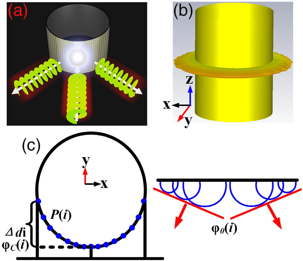
Figure 1.Conceptual illustration of the proposed conformal metasurface. (a) Schematic functionality under the illumination of a CP wave or an LP wave with arbitrary polarization. (b) Typical scattering pattern of a metallic cylinder. (c) Phase compensation inspired by the ray-tracing approach to restore two symmetric planar wavefronts.
For convenience and to obtain a simplistic design, the inversely symmetric phase gradients are designed only along the circumference, and those along the axial and radial directions are left constant. To obtain the required phase profile and minimize amplitude distortions (maximum efficiency) of edged meta-atoms at large incidence angles, the following discussion is presented. The position of the th element starting from a specific point (the original point in this study) should satisfy . Moreover, the initial phases of the elements were progressively increased with , . In these equations, is the lattice constant of the meta-atoms, is the radius of the cylinder, and is the number of elements utilized for shaping each high-efficiency beam. Therein, the meta-atom interval becomes larger and larger as it departs from the center to the edge, so that the performance of the resulting devices is dominated by the centered meta-atoms. However, each meta-atom is still periodically arranged when projected to the reference plane. Then, the imparted phase utilized to correct the distortions that are induced by the curved shape at is determined by considering the optical path difference: Therefore, the phase shift imposed by the metasurface should be . By using this design procedure, the arbitrary function can be exactly realized by the flexible conformal metasurface.
Now that the physics and strategy are clear, the next step focuses on the design of meta-atoms to map the determined phase distribution. To achieve a broad operation bandwidth, a rotational metallic Jerusalem cross with a PB phase is utilized, as shown in Fig. 2(a). The meta-atom is composed of a dielectric layer, an air spacer, and a backed metallic ground. The Jerusalem cross is etched on top of the dielectric layer with a dielectric constant of and thickness of 0.06 mm. Moreover, the air layer is utilized to enhance the high-efficiency bandwidth. Note that the air layer is not necessary if a trade-off is considered between the mechanical strength and performance. The criterion is utilized to guarantee near-unity CP conversion efficiency by suppressing any component that does not carry PB phase information [29–31]. Here, we employ the dispersion engineering method [42] to enable the slopes of and to be approximately equal within a broad bandwidth by modulating the length of three orthogonal bars of both “H” structures. As shown in Fig. 2(b), after cautious optimizations, we achieved in the range of 8.3–23.5 GHz, thus corresponding to a fractional bandwidth of 95.6%. Moreover, the reflection magnitude remains almost unity across the entire band, which is necessary for a high-efficiency superscatterer. As displayed in Fig. 2(c), the CP copolarization conversion efficiency is more than 93.5% in the range of 8.17–22.1 GHz, where the cross-polarization component (less than 0.25) is almost suppressed.

Figure 2.Topology and EM properties of the broadband PB meta-atom. (a) Element structure. EM response under illumination of (b) an -polarized LP wave, and CP waves of (c) normal and (d) oblique incidence. The geometrical parameters are optimized and detailed as , , , , , , , and .
Finally, the EM response under oblique illumination is displayed in Fig. 2(d). We can see that the efficiency and bandwidth (high-edge frequency shifted downward) decrease when the incidence increases from 0° to 45° at intervals of 15°. Nevertheless, a desirable efficiency of more than 87.7% is achieved when approaches 30°, and the efficiency remains higher than 70.5% even for . These features are critical for conformal design on arbitrary platforms with moderate curvature. In the above cases, the effect of contrast for different incidences on performance is negligible. However, the meta-atoms with large curvature are typically illuminated obliquely with a larger incidence of . In this case, the curvature affects the final performance of the resulting device through distortion of the magnitude, thus decreasing the efficiency. However, this decrease in efficiency can be rectified through amplitude compensation, which is beyond the scope of this work. Note that PB phases are typically affected by the angle of incidence [43]. However, it should be emphasized that the PB phases in this work are not significantly affected by the oblique incidence and are almost the same with those at normal incidence. The condition of broadband equals that for overcoming the angular limitation of a helicity-preserving mirror [43]. Therefore, in theory, our method using phase correction enables us to restore the EM wavefront of any curved platform with arbitrary curvature provided that the utilized meta-atom can work with high efficiency at a large incidence.
By progressively rotating the meta-atoms through an appropriate , we can achieve a PB phase of under CP wave excitation. As a consequence, the imposed correctional phase calculated using Eq. (1) can be realized by rotating the aforementioned meta-atoms with an appropriate at predicted positions. Then, the superscatterer can be realized by wrapping the flexible conformal metasurface over a conducting cylinder.
To prove the principle, we first employ a total of 21 dipoles that were mounted on the cylindrical surface with to mimic a conformal metasurface, as shown in Fig. 3(a). Each dipole is spaced with progressively enlarged distance along the circumference and is fed with the same amplitude but specific phase determined by using the aforementioned procedure at 12 GHz. In such a case, the effect of scattering amplitude loss (distortion) induced by the curvature can be avoided. Because of the shielding effect, a half-circle of all 21 dipoles is necessary. Different from the scattering scenario, we require to shape the radiation wave to the desired directions because no illumination phase error is induced. For a comprehensive study, three dipole arrays are considered on the same curved platform, and the corresponding phases are displayed in Fig. 3(b). The first dipole array (case 1) is designed with two beams directed toward . The phase tolerance at is compensated and minimized point by point on the basis of the following equation:
Figure 3.Numerical characterization of three dipole arrays, each forming a half-circle with to mimic a conformal metasurface. The radiation or scattering intensity at each frequency is first normalized to the total energy across the entire illumination region [] and then normalized to the maximum intensity . Three dipole arrays are considered: directional radiation at (case 1), high-efficiency anomalous radiation at (case 2), and deteriorative radiation (case 3). In cases 1 and 2, the phases are exactly designed. However, in case 3, no phase correction is applied. (a) Topology of the dipole array; inset shows the typical 3D radiation pattern in case 2. (b) Corresponding exciting phases of each dipole in three cases. Far-field radiation power intensity of three dipole arrays in (c) case 1, (d) case 2, and (e) case 3.
The other two dipole arrays (cases 2 and 3) contain the aforementioned linear gradient phases []. However, in case 3, the linear phases are superposed with the compensation phase for the curvature.
As expected in Figs. 3(c) and 3(d), highly desirable radiation patterns are clearly observed in the range of 6–18 GHz, i.e., two symmetric radiation beams with enhanced intensity directed toward in case 1, whereas two high-efficiency anomalous beams steered at with specular radiations almost suppressed in case 2. The highly concentrated beam was steered from 69.6° at 8 GHz to 24.6° at 18 GHz. The slightly enhanced specular radiation and the distorted beam angle at low frequencies are attributable to the reduced electrical array aperture, and the ray-tracing approximation introduces some tolerances. Nevertheless, this does affect the verification of our compensation strategy. This declaration finds strong support from the almost completely deteriorative radiations (emanative radiations with dispersive intensity) in case 3; see Fig. 3(e). A clear beam cannot be observed; instead, the power intensity is discretized toward numerous directions without any phase correction, thus illustrating the effectiveness of our approach.
3. NUMERICAL AND EXPERIMENTAL RESULTS
We now further evaluated the performance of our conformal metasurfaces by replacing the dipoles with real PB meta-atoms. For a comprehensive study, two metallic cylindrical platforms were utilized with and , in which a total of 21 and 33 meta-atoms were accommodated, respectively. The inhomogeneously arranged position and rotated angle of each meta-atom along the circumference were determined using the aforementioned strategy, as shown in Figs. 4(a) and 4(b). Figure 4(c) depicts the numerically calculated full-wave scattering intensity. As expected, two symmetric beams with almost equal intensity and completely suppressed specular scattering are clearly observed at all inspected frequencies within a broad bandwidth. This is very desirable for highly directive scattering enhancement. Moreover, perfect high-efficiency scattering occurs near the target frequency and shifts as varies from 18 to 15 GHz. This is quite physical because the required phase corresponding to the optical path difference is dispersive (frequency dependent), whereas the utilized correctional phase is constant. The phase distortion accounts for the enhanced normal scattering at frequencies substantially different from . Moreover, the beam angle of our superscatterer decreases with the frequency. This finding deviates from the conclusion drawn from theory and planar metasurface of the same projected size. This deviation can be attributed to the reflection magnitude loss of each meta-atom induced by the curvature. Such a deviation is substantial at low frequencies because the metasurface becomes electrically large, and thus, the reflection magnitude uniformity of each meta-atom is worsened. This finding is especially true for the edged meta-atoms, for which the incidence angle of the impinging wave is relatively large. However, the curvature effect becomes weak as the frequency increases because the curved metasurface can be approximated as a planar plate. This proposal is verified by analyzing the far-field patterns of the dipole arrays and planar metasurface displayed in Fig. 3 and Fig. 4(c), respectively, where the magnitude of each meta-atom or dipole is near unity. Therein, in both cases, the reflection angles are in good agreement with the theoretical ones predicted by .
Figure 4.Numerical characterization of conformal metasurfaces on a cylinder with . (a) Metasurface topology. (b) Numerically calculated full wave. (b) 3D and (c) 2D scattering power intensity in CST Microwave Studio. In the simulation setup, there is only one meta-atom along the axis, and the periodic boundary is assigned to mimic an infinitely high metasurface. The remaining four walls are assigned as the open boundary. For a comprehensive study, the metasurface is designed at different values of 18, 15, and 10 GHz.
For verification, we fabricated a proof-of-concept sample mounted on a cylinder with and . Because the available CP horns in the laboratory operate within 6–18 GHz, we designed another metasurface target at that frequency band, as shown in Figs. 5 and 6. As can be seen, the scattering behavior was similar to that observed in Fig. 4. Again, two high-efficiency scattering patterns were clearly observed. Such behavior sharply contrasts with that of the bare cylinder, where the scattering is almost homogeneous across the circumference (flat curve in Fig. 6). The total scattering by the metasurface-coated cylinders is very close to that of the flat conducting plate with the same projected size. The operation band with a precise steering angle shifts as shifts for a conformal metasurface. However, almost identical beam direction is achieved in the theoretical and numerical calculations for the planar metasurface. Moreover, the beam is narrowed when increases from 95 to 156 mm due to the contribution of the array factor. For the bare cylinder, the specular scattering enhances progressively as the frequency increases and finally dominates the energy across the azimuth like a planar metallic plate. This occurs because a curved surface can be approximated as a plane at high frequencies.
Figure 5.Numerical characterization of conformal metasurfaces on cylinders with and . The geometrical parameters of the utilized basic meta-atom are detailed as , , , , , , , and . The conformal metasurface is designed at different of 10, 12, and 15 GHz.
Figure 6.Numerically calculated RCSs of the conformal metasurface, cylinder, and planar plate that varies with the scattering angles and frequencies. The conformal metasurface wrapping over the cylinder of is designed at 10 GHz.
Figure 7(a) displays a photograph of the fabricated flexible sample with a planar area of . In the fabrication, we first attached a double-faced cardboard with and thickness of 4 mm on the metallic cylinder. Subsequently, the super-thin film was fixed to the cardboard. The sample was then characterized in a microwave anechoic chamber by using an angle-resolved bistatic scattering experimental setup; also see Fig. 7(a). Two CP horns that exhibited a voltage standing wave ratio of less than 2.5 and axial ratio of less than 3.5 dB in the range of 6–18 GHz were adopted as the emitter and receiver. These horns were placed 0.8 m away from the sample and were connected to an Agilent N5230 C vector network analyzer through two 13-m-long cables. The emitting horn and metasurface were fixed on a large foam that could be freely rotated along its axial center. Moreover, the receiving horn was aligned with the metasurface and recorded the signals that were scattered in the range of .
Figure 7.Experimental characterization of a conformal metasurface wrapped on a cylinder with an . (a) Photograph of the fabricated sample and angle-resolved bistatic RCS measurement setup. (b) Copolarized and (c) cross-polarized scattering component of the superscatterer. (d) Comparison of the efficiency between experiments and numerical calculations. The efficiency is defined as the ratio of anomalously reflected dual-beam intensity [] and totally reflected energy [] obtained by integrating the scattered-field intensity across the azimuth. Here, and are the reflection angles of the normal and anomalous modes, respectively. The aforementioned definition of efficiency measures the effectiveness of wavefront restoration. The stronger the dual-beam intensity, the less energy is dispersed to other directions, and the higher efficiency is due to energy conservation. (e) Cross-polarized scattering intensity of the bare metallic cylinder.
As shown in Fig. 7(b), very well-defined dual beams can be clearly observed in the range of 8–18 GHz. However, the cross-polarized scattering normalized to the copolarized scattering is negligible within 8–17 GHz; see Fig. 7(c). Thus, high conversion efficiency is obtained because is maintained. Therefore, we obtain a high efficiency of approximately 82% (90.3%) in measurement (simulation) across the range of 8–18 GHz, as shown in Fig. 7(d). In contrast to a bare cylinder, for which the reflection is approximately averaged across the azimuth, the highly concentrated scattering is very desirable for a metasurface-covered cylinder, as shown in Fig. 7(e). The slightly reversed beam-angle variation trend at low- and upper-edge frequencies between measurements in Fig. 7(b) and theory in Fig. 3 is the same as that discussed between simulations in Fig. 4, Fig. 5, and theory. Moreover, the measured scattering beamwidth is slightly larger than that observed in theory and simulations and is due to the nonideal plane wavefront of the transmitting horn.
The high-efficiency strong scattering can be further verified by analyzing Fig. 8. The slightly deteriorative patterns in experiments, in particular the asymmetric scattering intensity of the dual beams and undesirable scattering at other angles, can be attributed to the incoherence and misalignment of the flexible film and cylinder in the assembly. The slight deviation in the anomalous reflection angles obtained theoretically and experimentally is due to the magnitude distortion of edged meta-atoms, as previously discussed. In addition to the phase compensation, the simultaneous independent magnitude compensation of each meta-atom would overcome the distorted reflection angle. It should be emphasized that although an accurate conformal design is target at normal incidence and the wave reflection direction is also not flexible, the versatile complex wavefront control (random incidence and beam direction in practice) can be engineered by using smart sensors and tunable techniques based on the solid fundamentals established in this study.
Figure 8.Measured RCSs of the bare metallic cylinder and the conformal superscatterer at six selected frequencies of 8, 10, 12, 14, 16, and 18 GHz.
4. CONCLUSIONS
To sum up, we have proposed and verified a general method to design flexible high-efficiency superscatterers that can exhibit the desired broadband performance as exhibited by their planar counterparts. The geometrical form of the superscatterer can be decoupled from its EM function, enabling the metasurface to be applied to nonplanar platforms and stringent packaging. For verification, a set of conformal metasurfaces were designed at microwave frequency by modulating the nondispersive PB phase. A dual planar wave with minimized wavefront error was recovered at two predicted angles because a perfect phase profile was restored at each point of the curved surfaces by using the ray-tracing technique. Theoretical, numerical, and experimental results coincide well, indicating that the measured (simulated) efficiency of anomalous reflection can approach more than 82% (90.3%) in the range of 8–18 GHz. Our strategy, low profile and flexible, affords a possible avenue to generate EM superscattering for any curved surface with a versatile beam number and beam angle without requiring polarization considerations.
References
[1] L. Josefsson, P. Persson. Conformal Array Antenna Theory and Design(2006).
[2] J. J. Wang, D. J. Triplett, C. J. Stevens. Broadband/multiband conformal circular beam-steering array. IEEE Trans. Antennas Propag., 54, 3338-3346(2006).
[3] H.-X. Xu, S. Ma, X. Ling, X. Zhang, S. Tang, T. Cai, S. Sun, Q. He, L. Zhou. Deterministic approach to achieve broadband polarization-independent diffusive scatterings based on metasurfaces. ACS Photon., 5, 1691-1702(2018).
[4] H.-X. Xu, G. M. Wang, K. Ma, T. J. Cui. Superscatterer illusions without using complementary media. Adv. Opt. Mater., 2, 572-580(2014).
[5] N. Yu, P. Genevet, M. A. Kats, F. Aieta, J. Tetienne, F. Capasso, Z. Gaburro. Light propagation with phase discontinuities: generalized laws of reflection and refraction. Science, 334, 333-337(2011).
[6] S. Sun, Q. He, S. Xiao, Q. Xu, X. Li, L. Zhou. Gradient-index meta-surfaces as a bridge linking propagating waves and surface waves. Nat. Mater., 11, 426-431(2012).
[7] F. Aieta, P. Genevet, N. Yu, M. A. Kats, Z. Gaburro, F. Capasso. Out-of-plane reflection and refraction of light by anisotropic optical antenna metasurfaces with phase discontinuities. Nano Lett., 12, 1702-1706(2012).
[8] N. Yu, F. Capasso. Flat optics with designer metasurfaces. Nat. Mater., 13, 139-150(2014).
[9] M. Kim, A. M. Wong, G. V. Eleftheriades. Optical Huygens’ metasurfaces with independent control of the magnitude and phase of the local reflection coefficients. Phys. Rev. X, 4, 041042(2014).
[10] L. Liu, X. Zhang, M. Kenney, X. Su, N. Xu, C. Ouyang, Y. Shi, J. Han, W. Zhang, S. Zhang. Broadband metasurfaces with simultaneous control of phase and amplitude. Adv. Mater., 26, 5031-5036(2014).
[11] F. Aieta, M. A. Kats, P. Genevet, F. Capasso. Multiwavelength achromatic metasurfaces by dispersive phase compensation. Science, 347, 1342-1345(2015).
[12] S. Sun, K. Yang, C. Wang, T. Juan, W. T. Chen, C. Y. Liao, Q. He, S. Xiao, W. Kung, G. Guo. High-efficiency broadband anomalous reflection by gradient meta-surfaces. Nano Lett., 12, 6223-6229(2012).
[13] X. Zhang, Z. Tian, W. Yue, J. Gu, S. Zhang, J. Han, W. Zhang. Broadband terahertz wave deflection based on C-shape complex metamaterials with phase discontinuities. Adv. Mater., 25, 4567-4572(2013).
[14] C. Pfeiffer, N. K. Emani, A. M. Shaltout, A. Boltasseva, V. M. Shalaev, A. Grbic. Efficient light bending with isotropic metamaterial Huygens’ surfaces. Nano Lett., 14, 2491-2497(2014).
[15] Z. Liu, Z. Li, Z. Liu, J. Li, H. Cheng, P. Yu, W. Liu, C. Tang, C. Gu, J. Li. High-performance broadband circularly polarized beam deflector by mirror effect of multinanorod metasurfaces. Adv. Funct. Mater., 25, 5428-5434(2015).
[16] X. Chen, L. Huang, H. Mühlenbernd, G. Li, B. Bai, Q. Tan, G. Jin, C. Qiu, S. Zhang, T. Zentgraf. Dual-polarity plasmonic metalens for visible light. Nat. Commun., 3, 1198(2012).
[17] X. Ni, S. Ishii, A. V. Kildishev, V. M. Shalaev. Ultra-thin, planar, Babinet-inverted plasmonic metalenses. Light Sci. Appl., 2, e72(2013).
[18] X. Ling, X. Zhou, K. Huang, Y. Liu, C. Qiu, H. Luo, S. Wen. Recent advances in the spin Hall effect of light. Rep. Prog. Phys., 80, 066401(2017).
[19] X. Chen, M. Chen, M. Q. Mehmood, D. Wen, F. Yue, C. W. Qiu, S. Zhang. Longitudinal multifoci metalens for circularly polarized light. Adv. Opt. Mater., 3, 1201-1206(2015).
[20] N. K. Grady, J. E. Heyes, D. R. Chowdhury, Y. Zeng, M. T. Reiten, A. K. Azad, A. J. Taylor, D. A. Dalvit, H. Chen. Terahertz metamaterials for linear polarization conversion and anomalous refraction. Science, 340, 1304-1307(2013).
[21] T. J. Cui, M. Q. Qi, X. Wan, J. Zhao, Q. Cheng. Coding metamaterials, digital metamaterials and programmable metamaterials. Light Sci. Appl., 3, e218(2014).
[22] P. Genevet, N. Yu, F. Aieta, J. Lin, M. A. Kats, R. Blanchard, M. O. Scully, Z. Gaburro, F. Capasso. Ultra-thin plasmonic optical vortex plate based on phase discontinuities. Appl. Phys. Lett., 100, 013101(2012).
[23] J. Lin, J. B. Mueller, Q. Wang, G. Yuan, N. Antoniou, X. Yuan, F. Capasso. Polarization-controlled tunable directional coupling of surface plasmon polaritons. Science, 340, 331-334(2013).
[24] L. Huang, X. Chen, H. Mühlenbernd, H. Zhang, S. Chen, B. Bai, Q. Tan, G. Jin, K. Cheah, C. Qiu. Three-dimensional optical holography using a plasmonic metasurface. Nat. Commun., 4, 2808(2013).
[25] G. Zheng, H. Mühlenbernd, M. Kenney, G. Li, T. Zentgraf, S. Zhang. Metasurface holograms reaching 80% efficiency. Nat. Nanotechnol., 10, 308-312(2015).
[26] F. Monticone, N. M. Estakhri, A. Alù. Full control of nanoscale optical transmission with a composite metascreen. Phys. Rev. Lett., 110, 203903(2013).
[27] X. Yin, Z. Ye, J. Rho, Y. Wang, X. Zhang. Photonic spin Hall effect at metasurfaces. Science, 339, 1405-1407(2013).
[28] W. Luo, S. Xiao, Q. He, S. Sun, L. Zhou. Photonic spin Hall effect with nearly 100% efficiency. Adv. Opt. Mater., 3, 1102-1108(2015).
[29] H.-X. Xu, G. Wang, T. Cai, J. Xiao, Y. Zhuang. Tunable Pancharatnam-Berry metasurface for dynamical and high-efficiency anomalous reflection. Opt. Express, 24, 27836-27848(2016).
[30] H.-X. Xu, H. Liu, X. Ling, Y. Sun, F. Yuan. Broadband vortex beam generation using multimode Pancharatnam-Berry metasurface. IEEE Trans. Antennas Propag., 65, 7378-7382(2017).
[31] W. Luo, S. Sun, H. Xu, Q. He, L. Zhou. Transmissive ultrathin Pancharatnam-Berry metasurfaces with nearly 100% efficiency. Phys. Rev. Appl., 7, 044033(2017).
[32] X. Ling, X. Zhou, X. Yi, W. Shu, Y. Liu, S. Chen, H. Luo, S. Wen, D. Fan. Giant photonic spin Hall effect in momentum space in a structured metamaterial with spatially varying birefringence. Light Sci. Appl., 4, e290(2015).
[33] Y. Liu, X. Ling, X. Yi, X. Zhou, S. Chen, Y. Ke, H. Luo, S. Wen. Photonic spin Hall effect in dielectric metasurfaces with rotational symmetry breaking. Opt. Lett., 40, 756-759(2015).
[34] S. M. Kamali, A. Arbabi, E. Arbabi, Y. Horie, A. Faraon. Decoupling optical function and geometrical form using conformal flexible dielectric metasurfaces. Nat. Commun., 7, 11618(2016).
[35] M. Q. Mehmood, S. Mei, S. Hussain, K. Huang, S. Y. Siew, L. Zhang, T. Zhang, X. Ling, H. Liu, J. Teng. Visible-frequency metasurface for structuring and spatially multiplexing optical vortices. Adv. Mater., 28, 2533-2539(2016).
[36] L. Li, T. J. Cui, W. Ji, S. Liu, J. Ding, X. Wan, Y. B. Li, M. Jiang, C. Qiu, S. Zhang. Electromagnetic reprogrammable coding-metasurface holograms. Nat. Commun., 8, 197(2017).
[37] X. Ni, Z. J. Wong, M. Mrejen, Y. Wang, X. Zhang. An ultrathin invisibility skin cloak for visible light. Science, 349, 1310-1314(2015).
[38] Y. Shang, Z. Shen. Polarization-independent backscattering enhancement of cylinders based on conformal gradient metasurfaces. IEEE Trans. Antennas Propag., 65, 2386-2396(2017).
[39] Y. Zhang, L. Liang, J. Yang, Y. Feng, B. Zhu, J. Zhao, T. Jiang, B. Jin, W. Liu. Broadband diffuse terahertz wave scattering by flexible metasurface with randomized phase distribution. Sci. Rep., 6, 26875(2016).
[40] D. Germain, D. Seetharamdoo, S. Nawaz Burokur, A. De Lustrac. Phase-compensated metasurface for a conformal microwave antenna. Appl. Phys. Lett., 103, 124102(2013).
[41] M. Dubois, C. Shi, Y. Wang, X. Zhang. A thin and conformal metasurface for illusion acoustics of rapidly changing profiles. Appl. Phys. Lett., 110, 151902(2017).
[42] H.-X. Xu, S. Sun, S. Tang, S. Ma, Q. He, G. Wang, T. Cai, H. Li, L. Zhou. Dynamical control on helicity of electromagnetic waves by tunable metasurfaces. Sci. Rep., 6, 27503(2016).
[43] S. Xiao, H. Mühlenbernd, G. Li, M. Kenney, F. Liu, T. Zentgraf, S. Zhang, J. Li. Helicity-preserving omnidirectional plasmonic mirror. Adv. Opt. Mater., 4, 654-658(2016).
[44] H.-X. Xu, S. Tang, X. Ling, W. Luo, L. Zhou. Flexible control of highly-directive emissions based on bifunctional metasurfaces with low polarization cross-talking. Ann. Phys., 529, 1700045(2017).


