


Jiangzhao Zhang, Huiliang Tang, Chu Wang, Xiaoxuan Wu, Yu Long. Latest Research Progress and Prospect of Process Planning Algorithms of Multiaxis Support-Free 3D Printing for Complex Structure[J]. Chinese Journal of Lasers, 2022, 49(14): 1402302
- Chinese Journal of Lasers
- Vol. 49, Issue 14, 1402302 (2022)
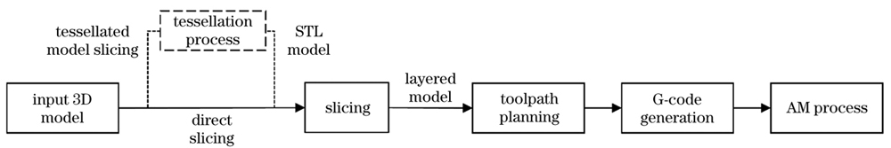
Fig. 1. A general workflow of 3D printing preprocessing
![Number of publications on multiaxis 3D printing[20]](/richHtml/zgjg/2022/49/14/1402302/img_02.jpg)
Fig. 2. Number of publications on multiaxis 3D printing[20]
Fig. 3. Non-uniform slicing method[30]
Fig. 4. Unit layer slicing method[31]. (a) Unit layer;(b) result of slicing; (c) unit layer after deposition
Fig. 5. Offset slicing method[32]. (a) Base surface of contour; (b) offset slices obtained from base surface
Fig. 6. An illustration of method proposed by Lee and Jee[33]. (a) STL model; (b) overhang/overcutting identification;(c) overhang/overcutting volume decomposition; (d)(e) slicing in multiple directions
Fig. 7. Illustration of decomposition-regrouping method[34]. (a) Sub-volumes, feature regions (red), and base region;(b) grouped sub-volumes; (c) slicing in multiple directions
Fig. 8. Cylindrical coordinate slicing method[35]. (a) Revolving part; (b) cylindrical coordinate; (c) intersection contour of slice with overhang structure; (d) mapped overhanging structure at Cartesian coordinate
Fig. 9. Nonplanar slicing method proposed by Zhao et al[36]. (a) Decomposed volumes; (b) offset surfaces; (c) trimmed surfaces; (d) five-axis toolpaths
Fig. 10. Non-uniform slicing method based on centroidal axis[37]. (a) Solid model; (b) centroidal axis; (c) centroidal axis and solid model; (d) decomposed result; (e) slicing result
Fig. 11. Illustration of method proposed by Wang et al[40]. (a) Input Y shape model; (b) three extracted skeletal polylines of
Fig. 12. Model decomposition method proposed by Wu et al[41]. (a) Input 3D model; (b) extracted skeleton; (c) distribution of shape diameter metric; (d) initial decomposition and print order results; (e) result after merging (B+A); (f) final result after fine decomposition (meet manufacturability requirements)
Fig. 13. Volume decomposition algorithm proposed by Dai et al[48]. (a) Input 3D model; (b) voxel discretization and accumulative voxel sequence; (c) generating curved layers based on Fig. 13(b); (d) a detailed view on a computed toolpath
Fig. 14. Volume decomposition algorithm proposed by Xu et al[51]. (a) Original mesh model; (b) generated iso-geodesic contours; (c) reconstructed surface layers with no intersection
Fig. 15. Volume decomposition algorithm proposed by Fang et al[55]. (a) A bunny-head model H is represented by a tetrahedral mesh T; (b) principal stresses with values are visualized by colors; (c) a vector-field V(x) is optimized according to the principle of reinforcement and the fabrication constraints; (d) a scalar-field G(x) is obtained by enforcing ∇G(x) to follow V(x); (e) preliminary curved layers are generated by extracting the iso-surfaces from G(x); (f) an orientation of fabrication is determined by considering the accessibility of printer head and regions with large overhangs are detected by a sampling based method; (g) a vector-field V(x) is extrapolating V(x) for supporting structure; (h) final curved layers are extracted from the governing fields for 3D printing; (i) toolpaths are generated for curved layers according to the principal stresses
Fig. 16. Illustrate of ellipsoid based curved slicing[57]. (a) A characteristic ellipsoid of a sub-entity; (b) intermediate ellipsoid generation
Fig. 17. Schematic of the method proposed by Kapil et al[59]. (a) Position of cladding torch and substrate; (b) tilted substrate for 5-axis outer contour deposition; (c) vertical substrate for 2.5 axis area filling
Fig. 18. Horizontal planes with equal distances h between each other generate different layer thicknesses in the welding direction[61]
Fig. 19. A novel deposition strategy for creating overhangs proposed by Dai et al[62-63]. (a) A common strategy of depositing filling paths layer by layer; (b) a novel strategy of depositing the overhanging segment as a support; (c) deposition of filling paths
Fig. 20. Illustrate of staircase effect under three conditions[23]. (a) P⊆Q; (b) Q⊆P; (c) P⊄Q
Fig. 21. Comparison of methods between planar slicing and slightly curved slicing[68]. (a) Planner slicing method; (b) slightly curved slicing method
Fig. 22. Helical slicing method[69]. (a) Model input; (b) generate slicing planes; (c) obtain planar slices; (d) generate direction vectors; (e) generate helical points; (e) generate helical toolpath
Fig. 23. Slicing and path generation method and actual print results for RotBot[81]
Fig. 24. Singularity aware motion planning[93]. (a) Singularity aware optimization is not used; (b) singularity aware optimization is used
|
Table 1. Comparison of decomposition results based on constrained optimization methods[46]
| |||||||||||||||||||||||||||||||||||||||||||||||||||||||||||||||||
Table 2. Comparison of characteristics of constraint-based optimization methods
| ||||||||||||||||||||||||||||||||||||||||||||||||||||||||||||||||||||||||||||||||||||||||||||||
Table 3. Summary and comparison of methods based on curved layer decomposition
|
Table 4. Summary of process planning methods of multi-axis support-free 3D printing

Set citation alerts for the article
Please enter your email address
© Copyright 2018-2021 | Chinese Laser Press. All Rights Reserved 沪ICP备15018463号-20