Fig. 1. Schematic diagram of SPDC correlation photon generation
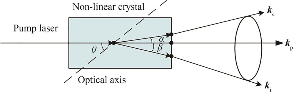
Fig. 2. Schematic diagram of noncollinear angles of correlated photons pumped by BBO crystals under different phase matching angles
Fig. 3. Spectral photon rate distribution of correlated photons
Fig. 4. Schematic diagram of absolute quantum efficiency calibration of single photon detectors based on SPDC
Fig. 5. Overall design scheme of compact low light radiance meter
Fig. 6. 3D diagram of the first and second channel optical path
Fig. 7. Galilean shrink beam structure
Fig. 8. Structure of the first and second channel coupled lens set
Fig. 9. Full field of view spot diagram of image surface light spot in first channel
Fig. 10. Full field of view spot diagram of image surface light spot in channel 2
Fig. 11. Fiber coupling flow chart
Fig. 12. Optical fiber transmission diagram
Fig. 13. 3D diagram of the third channel ZEMAX optical path
Fig. 14. Full field of view spot diagram of image surface light spot in channel 3
| Element | Main function |
|---|
| Glantler prism | Adjust the pump laser polarization state to linear polarization | | Half-wave plate | Enables/disables parametric downconversion | | Off-axis parabolic mirror | Reduce the influence of color difference and uncertainty and improve the equivalence | | Filter module | Filter pump light and improve the signal-to-noise ratio of correlated photon measurement |
|
Table 1. Functions of some components of radiance meter
| Parameter | Technical index |
|---|
| Wavelength range | 460 ~1 550 nm | | Observation bandwidth | <12 nm | | Observed field of view | ±1° | | Field aperture | 100 μm | | Transmittance of optical system | 0.15 | | Si APD | Dark count rate | <500/s | | Saturation count rate | 20 M/s | | Quantum efficiency | 69%@685 nm | | InGaAs APD | Dark count rate | <1 000/s | | Saturation count rate | 1 M/s | | Quantum efficiency | 10%@1 550 nm | | Target radiance | 1×10⁻⁹~1×10⁻⁶ W/(cm2·sr·nm) |
|
Table 2. Estimation of observed radiance range of low light radiance meter
| Main parameter | Index requirement |
|---|
| Operating wavelength range | 460~1 550 nm | | Pump laser wavelength | 355 nm | | Crystal type | BBO | | Coincidence band | 460 nm/1550 nm,580 nm/910 nm, 610 nm/850 nm,685 nm/737 nm | | Working mode | Self-calibration model and radiation observation model | | Observation field of view | ±1° | | Spectral radiance measurement range | 1×10⁻⁹~1×10⁻⁶ W/(cm2·sr·nm) | | Measurement uncertainty | 8%(k=2) |
|
Table 3. Main performance parameters of low light radiance meter
| Wavelength/nm | Transmission | Thickness/mm |
|---|
| 460 | 0.953 | 10 | | 480 | 0.966 | 10 | | 550 | 0.989 | 10 | | 600 | 0.993 | 10 | | 700 | 0.996 | 10 | | 850 | 0.998 | 10 | | 900 | 0.998 | 10 | | 1000 | 0.998 | 10 | | 1400 | 0.998 | 10 | | 1600 | 0.998 | 10 |
|
Table 4. H-ZF52A glass transmission
| Wavelength/nm | Transmission | Thickness/mm |
|---|
| 460 | 0.886 | 10 | | 480 | 0.921 | 10 | | 550 | 0.979 | 10 | | 600 | 0.989 | 10 | | 700 | 0.993 | 10 | | 850 | 0.995 | 10 | | 900 | 0.996 | 10 | | 1000 | 0.998 | 10 | | 1400 | 0.998 | 10 | | 1600 | 0.996 | 10 |
|
Table 5. H-ZF88 glass transmission
| Surface number | Surface type | Radius of curvature/mm | Surface thickness/mm | Material | Half-height of aperture/mm |
|---|
| 1 | Sphere | INFINITY | 4.3 | H-ZPK1A | 12 | | 2 | Sphere | -31.947 | 4 | AIR | 12 | | 3 | Sphere | 18.000 | 11 | H-ZPK1A | 11 | | 4 | Sphere | 18.000 | 3 | H-ZF52A | 11 | | 5 | Sphere | 49.304 | 11.175 | AIR | 6 |
|
Table 6. First channel focusing optical path parameter
| Surface number | Surface type | Radius of curvature/mm | Surface thickness/mm | Material | Half-height of aperture/mm |
|---|
| 1 | Sphere | INFINITY | 4.3 | H-LAF52 | 12 | | 2 | Sphere | -31.344 | 4 | AIR | 12 | | 3 | Sphere | 18.000 | 11 | H-ZPK1A | 11 | | 4 | Sphere | 18.000 | 3 | H-ZF52A | 11 | | 5 | Sphere | 20.927 | 17.175 | AIR | 6 |
|
Table 7. Second channel focusing optical path parameter
| Tolerance parameter | Set value |
|---|
Radius of curvature Surface thickness | 2 aperture 0.02 mm | | S+A irregularity | 0.2 aperture | | Surface/component eccentricity | 0.02 mm | | Surface/element tilt | 0.02° | | Refractive index | 0.001% | | Abbe | 0.05% |
|
Table 8. Tolerance setting parameters table
| Percentage | RMS radius/μm |
|---|
| 98%> | 7.20 | | 90%> | 6.27 | | 80%> | 5.79 | | 50%> | 5.07 | | 20%> | 4.57 | | 10%> | 4.41 | | 2%> | 4.14 |
|
Table 9. Tolerance analysis results of first channel
| Percentage | RMS radius /μm |
|---|
| 98%> | 8.91 | | 90%> | 7.08 | | 80%> | 6.17 | | 50%> | 4.79 | | 20%> | 3.70 | | 10%> | 3.37 | | 2%> | 2.92 |
|
Table 10. Tolerance analysis results of channel 2
| Surface number | Surface type | Radius of curvature/mm | Surface thickness/mm | Material | Half-height of aperture/mm |
|---|
1 2 | Sphere Sphere | 179.703 -24.030 | 11 4.5 | H-ZPK1A H-ZF52A | 16 16 | | 3 | Sphere | INFINITY | 1 | AIR | 18 | | 4 | Sphere | 35.021 | 10 | H-ZPK1A | 16 | | 5 | Sphere | -35.820 | 4.5 | H-ZF52A | 16 | | 6 | Sphere | -81.006 | 55.889 | AIR | 18 |
|
Table 11. Third channel focusing optical path parameter table
| Percentage | RMS radius/μm |
|---|
| 98%> | 3.44 | | 90%> | 2.60 | | 80%> | 2.20 | | 50%> | 1.64 | | 20%> | 1.35 | | 10%> | 1.25 | | 2%> | 1.15 |
|
Table 12. Tolerance analysis results of channel 3
| Channel | Observation band/nm | Optimal value of light spot in image plane/μm | Worst value of light spot in image surface/μm | Design index/μm |
|---|
| 1 | 460~685 | 59.94 | 97.34 | 300 | 2 3 | 737~910 1 550 | 51.44 42.64 | 90.64 52.12 | 300 62.5 |
|
Table 13. Extreme spot diameters in the image plane of three channels