• Chinese Optics Letters
  • Vol. 22, Issue 3, 031303 (2024)
Heming Hu1、2, Shiping Liu1, Tianwen Li1, Yongjie Fan1, Hua Chen1、*, and Qing Fang1、**
Author Affiliations
  • 1College of Science, Kunming University of Science and Technology, Kunming 650093, China
  • 2College of Electronic Science and Engineering, Jilin University, Jilin 130012, China
  • show less
    DOI: 10.3788/COL202422.031303 Cite this Article Set citation alerts
    Heming Hu, Shiping Liu, Tianwen Li, Yongjie Fan, Hua Chen, Qing Fang. Ultralow cross talk arrayed waveguide grating integrated with tunable microring filter array[J]. Chinese Optics Letters, 2024, 22(3): 031303 Copy Citation Text show less
    (a) Schematic diagram of normal AWG; (b) schematic diagram of the designed AWG; (c) optical micrographs of the fabricated ultralow cross talk AWG.
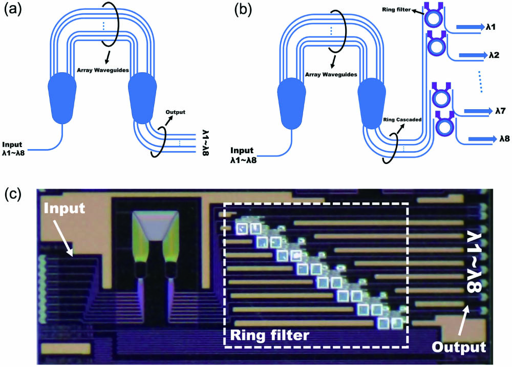
    Fig. 1. (a) Schematic diagram of normal AWG; (b) schematic diagram of the designed AWG; (c) optical micrographs of the fabricated ultralow cross talk AWG.
    Simulated transmission spectrum of AWG (with and without errors) and MRR for the central wavelength of 1550 nm.
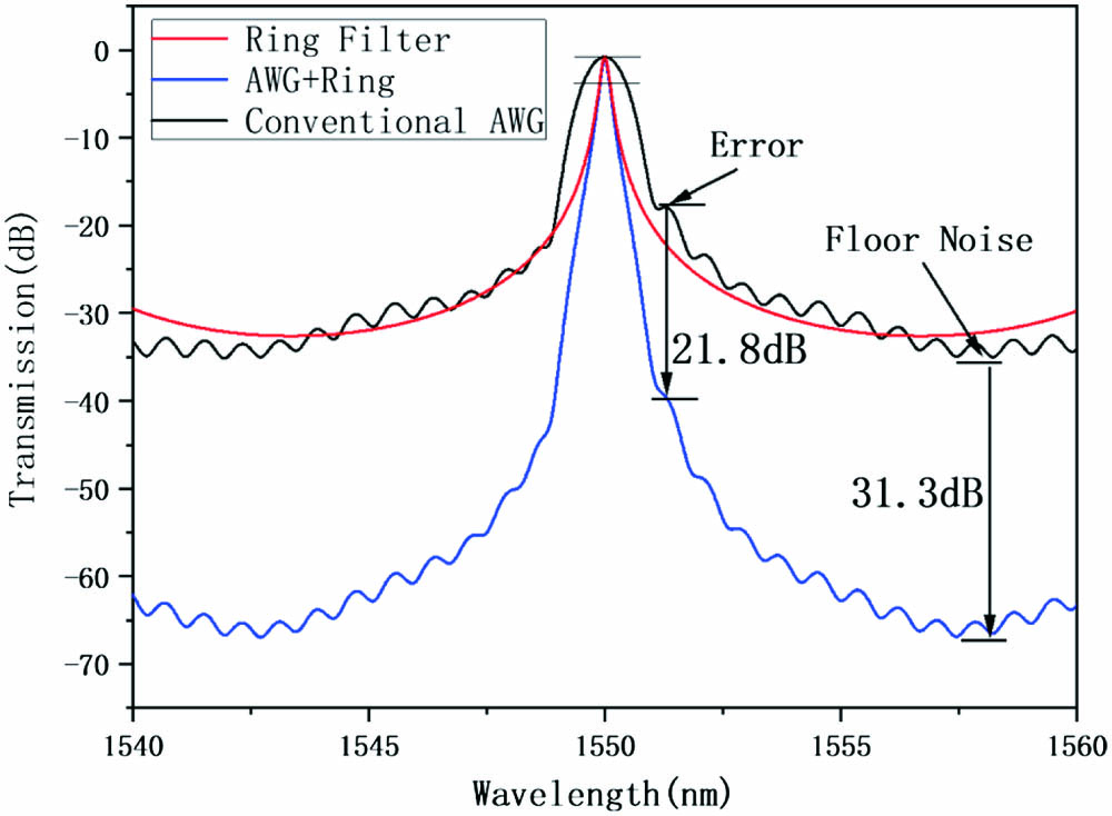
    Fig. 2. Simulated transmission spectrum of AWG (with and without errors) and MRR for the central wavelength of 1550 nm.
    (a) Schematic illustration of the ring resonator; (b) optical micrograph of the ring resonator.
    Fig. 3. (a) Schematic illustration of the ring resonator; (b) optical micrograph of the ring resonator.
    (a) Transmission spectra of the MRR drop side for both the simulation and actual test; (b) measured I-V curve and power consumption of the MRR; (c) relation between resonance wavelength and applied electric power on the heater of MRR; (d) shift of the resonance wavelength of MRR under 7.8 V voltage (red) and wavelength shift of the AWG first channel under voltage application (black).
    Fig. 4. (a) Transmission spectra of the MRR drop side for both the simulation and actual test; (b) measured I-V curve and power consumption of the MRR; (c) relation between resonance wavelength and applied electric power on the heater of MRR; (d) shift of the resonance wavelength of MRR under 7.8 V voltage (red) and wavelength shift of the AWG first channel under voltage application (black).
    Measured spectra of AWG. (a) Reference normal AWG; (b) ultralow cross talk AWG integrated with MRRs.
    Fig. 5. Measured spectra of AWG. (a) Reference normal AWG; (b) ultralow cross talk AWG integrated with MRRs.
    AWGRing
    ParameterValueParameterValue
    Central wavelength1.55 µmCentral wavelength1.55 µm
    Channel spacing3.2 nmRadius7.6 µm
    Number of input channels1Gap200 nm
    Number of output channels8Modulation methodThermos effect
    Number of arrayed WGs23Heater materialTiN
    Diffraction order50Heater width3 µm
    Path difference28 µmDistance of heater and WG1.2 µm
    Free spectral range25 nmFree spectral range12.8 nm
    Arrayed WG width0.8 µm
    Pitch width of arrayed WG2.8 µm
    Table 1. Design Parameters of the AWG and Ring
    ChannelCenter Wavelength(nm)Applied Voltage(V)
    11540.191.80
    21543.224.49
    31546.586.29
    41549.757.65
    51552.802.60
    61555.904.93
    71558.886.41
    81562.167.80
    Table 2. Various Voltages Applied on the MRR to Overlap with the Center Wavelength of Each Channel of the AWG
    Heming Hu, Shiping Liu, Tianwen Li, Yongjie Fan, Hua Chen, Qing Fang. Ultralow cross talk arrayed waveguide grating integrated with tunable microring filter array[J]. Chinese Optics Letters, 2024, 22(3): 031303
    Download Citation