• High Power Laser Science and Engineering
  • Vol. 9, Issue 1, 010000e5 (2021)
Jie Feng1、2, Yifei Li3, Jinguang Wang3, Dazhang Li4、*, Changqing Zhu3, Junhao Tan3, Xiaotao Geng3, Feng Liu1、2, and Liming Chen1、2、*
Author Affiliations
  • 1Key Laboratory for Laser Plasmas (MoE), School of Physics and Astronomy, Shanghai Jiao Tong University, Shanghai200240, China
  • 2IFSA Collaborative Innovation Center and School of Physics and Astronomy, Shanghai Jiao Tong University, Shanghai200240, China
  • 3Beijing National Research Center of Condensed Matter Physics, Institute of Physics, CAS, Beijing100190, China
  • 4Institute of High Energy Physics, CAS, Beijing100049, China
  • show less
    DOI: 10.1017/hpl.2020.51 Cite this Article Set citation alerts
    Jie Feng, Yifei Li, Jinguang Wang, Dazhang Li, Changqing Zhu, Junhao Tan, Xiaotao Geng, Feng Liu, Liming Chen. Optical control of transverse motion of ionization injected electrons in a laser plasma accelerator[J]. High Power Laser Science and Engineering, 2021, 9(1): 010000e5 Copy Citation Text show less
    Experimental setup. (a) Laser intensity distribution measured in front of, at and behind, respectively, the focal spot in the case of a perfect focus situation. (b) Laser intensity distribution measured after adjusting the posture of the OAP mirror. (c) The top-view image of the plasma channel.
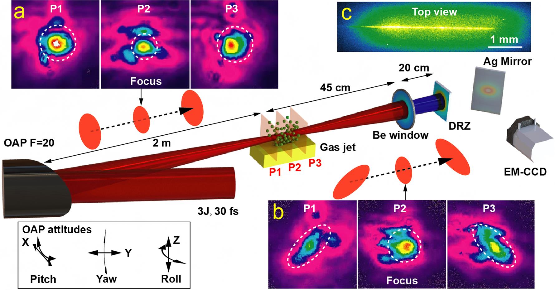
    Fig. 1. Experimental setup. (a) Laser intensity distribution measured in front of, at and behind, respectively, the focal spot in the case of a perfect focus situation. (b) Laser intensity distribution measured after adjusting the posture of the OAP mirror. (c) The top-view image of the plasma channel.
    Electron beam spatial distribution. The first three columns are driven by the asymmetrical focus, showing three different typical shapes. All of these electron beam profiles were acquired under the same experimental conditions. The last column is driven by the symmetrical focus. All of the angles refer to the included angle between the elliptical long axis and the horizontal axis.
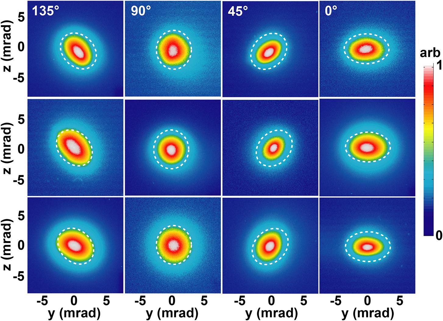
    Fig. 2. Electron beam spatial distribution. The first three columns are driven by the asymmetrical focus, showing three different typical shapes. All of these electron beam profiles were acquired under the same experimental conditions. The last column is driven by the symmetrical focus. All of the angles refer to the included angle between the elliptical long axis and the horizontal axis.
    Deflected electron distributions and charges for five consecutive shots. The red numbers are the total charges for electron energy above 80 MeV. (a) Asymmetrical focus. (b) Symmetrical focus.
    Fig. 3. Deflected electron distributions and charges for five consecutive shots. The red numbers are the total charges for electron energy above 80 MeV. (a) Asymmetrical focus. (b) Symmetrical focus.
    Laser plasma wakefield acceleration in 3D-PIC simulations. (a), (b) The cross-sections of the plasma bubble in the XY and XZ planes, respectively, driven by the symmetrical laser spot. (c), (d) The cross-sections driven by the asymmetrical laser spot. (e)–(g) The cross-sections (in the YZ plane) of the plasma bubble at different propagation positions, corresponding to the case of the symmetrical spot. (h)–(j) The cross-sections corresponding to the case of the asymmetrical focal spot at different propagation positions.
    Fig. 4. Laser plasma wakefield acceleration in 3D-PIC simulations. (a), (b) The cross-sections of the plasma bubble in the XY and XZ planes, respectively, driven by the symmetrical laser spot. (c), (d) The cross-sections driven by the asymmetrical laser spot. (e)–(g) The cross-sections (in the YZ plane) of the plasma bubble at different propagation positions, corresponding to the case of the symmetrical spot. (h)–(j) The cross-sections corresponding to the case of the asymmetrical focal spot at different propagation positions.
    Electron beam spots in 3D-PIC simulations. (a)–(c) Electron beam spots driven by a 45° slanted elliptical laser focus at different laser propagation distances (~485 μm, 685 μm and 885 μm) in nitrogen. (d) Corresponding to the case of the circular laser spot at a distance of ~885 μm. (e), (f) The phase spaces of the Py-z and Pz-y distributions, respectively, corresponding to the electrons in Figure 4(c). (g), (h) The phase spaces corresponding to the case of Figure 4(d).
    Fig. 5. Electron beam spots in 3D-PIC simulations. (a)–(c) Electron beam spots driven by a 45° slanted elliptical laser focus at different laser propagation distances (~485 μm, 685 μm and 885 μm) in nitrogen. (d) Corresponding to the case of the circular laser spot at a distance of ~885 μm. (e), (f) The phase spaces of the Py-z and Pz-y distributions, respectively, corresponding to the electrons in Figure 4(c). (g), (h) The phase spaces corresponding to the case of Figure 4(d).
    Analysis of transverse force for the electrons in the plasma wakefield. (a), (d) The cross-sections of the plasma bubble corresponding to the circular spot and the elliptical spot, respectively. (b), (c) The transverse force in the directions of y and z, respectively, corresponding to (a). (e), (f) The transverse force in the directions of y and z, respectively, corresponding to (d).
    Fig. 6. Analysis of transverse force for the electrons in the plasma wakefield. (a), (d) The cross-sections of the plasma bubble corresponding to the circular spot and the elliptical spot, respectively. (b), (c) The transverse force in the directions of y and z, respectively, corresponding to (a). (e), (f) The transverse force in the directions of y and z, respectively, corresponding to (d).
    Trajectories of the electrons driven by (a) circular laser focus and (b) elliptical laser focus.
    Fig. 7. Trajectories of the electrons driven by (a) circular laser focus and (b) elliptical laser focus.
    Jie Feng, Yifei Li, Jinguang Wang, Dazhang Li, Changqing Zhu, Junhao Tan, Xiaotao Geng, Feng Liu, Liming Chen. Optical control of transverse motion of ionization injected electrons in a laser plasma accelerator[J]. High Power Laser Science and Engineering, 2021, 9(1): 010000e5
    Download Citation