• High Power Laser Science and Engineering
  • Vol. 4, Issue 3, 03000e21 (2016)
Wanguo Zheng1、2, Xiaofeng Wei1, Qihua Zhu1、2, Feng Jing1, Dongxia Hu1、2, Jingqin Su1、2, Kuixing Zheng1, Xiaodong Yuan1, Hai Zhou1, Wanjun Dai1, Wei Zhou1, Fang Wang1, Dangpeng Xu1, Xudong Xie1, Bin Feng1, Zhitao Peng1, Liangfu Guo1, Yuanbin Chen1, Xiongjun Zhang1, Lanqin Liu1, Donghui Lin1, Zhao Dang1, Yong Xiang1, and Xuewei Deng1、2
Author Affiliations
  • 1Laser Fusion Research Center, China Academy of Engineering Physics, P.O. Box 919-988, MianYang 621900, China
  • 2IFSA Collaborative Innovation Center, Shanghai Jiao Tong University, Shanghai 200240, China
  • show less
    DOI: 10.1017/hpl.2016.20 Cite this Article Set citation alerts
    Wanguo Zheng, Xiaofeng Wei, Qihua Zhu, Feng Jing, Dongxia Hu, Jingqin Su, Kuixing Zheng, Xiaodong Yuan, Hai Zhou, Wanjun Dai, Wei Zhou, Fang Wang, Dangpeng Xu, Xudong Xie, Bin Feng, Zhitao Peng, Liangfu Guo, Yuanbin Chen, Xiongjun Zhang, Lanqin Liu, Donghui Lin, Zhao Dang, Yong Xiang, Xuewei Deng. Laser performance of the SG-III laser facility[J]. High Power Laser Science and Engineering, 2016, 4(3): 03000e21 Copy Citation Text show less
    Schematic of the SG-III laser facility.
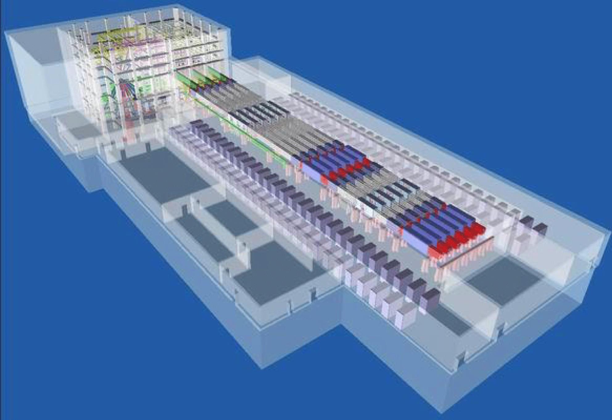
    Fig. 1. Schematic of the SG-III laser facility.
    Schematic of one of the 48 beamlines in the SG-III laser facility. CM: cavity mirror; DM: deformable mirror; AMP: amplifier plate; L: lens; CSF/TSF: cavity/transport spatial filter; WP: wedge plate; TM: transport mirror; FCU: frequency conversion unit; BSG: beam sampling grating; CPP: continuous phase plate; WFL: wedged focus lens; PMU: parameter measurement unit; DS: debris shield; FD: front end; PAM: preamplifier; LPC: large pockels cell; BM: beam mirror; BR: beam reverser.
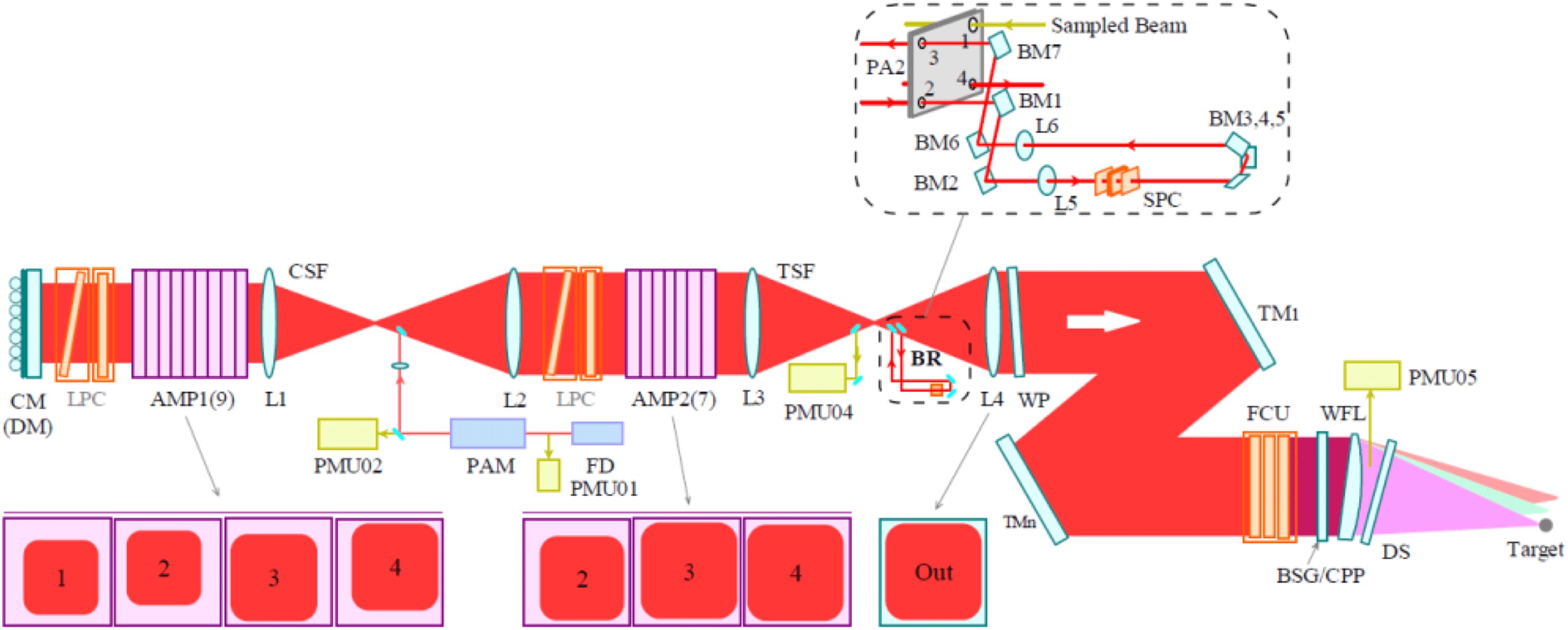
    Fig. 2. Schematic of one of the 48 beamlines in the SG-III laser facility. CM: cavity mirror; DM: deformable mirror; AMP: amplifier plate; L: lens; CSF/TSF: cavity/transport spatial filter; WP: wedge plate; TM: transport mirror; FCU: frequency conversion unit; BSG: beam sampling grating; CPP: continuous phase plate; WFL: wedged focus lens; PMU: parameter measurement unit; DS: debris shield; FD: front end; PAM: preamplifier; LPC: large pockels cell; BM: beam mirror; BR: beam reverser.
    The schematic of the U-tum reverser and its influence on the wavefront distortion.
    Fig. 3. The schematic of the U-tum reverser and its influence on the wavefront distortion.
    Schematics of the two adaptive optics systems in SG-III laser facility.
    Fig. 4. Schematics of the two adaptive optics systems in SG-III laser facility.
    The tested result of the small signal gain coefficients of each beamline in SG-III.
    Fig. 5. The tested result of the small signal gain coefficients of each beamline in SG-III.
    Experimental results of the 7.5 kJ $1{\it\omega}$ output capability.
    Fig. 6. Experimental results of the 7.5 kJ $1{\it\omega}$ output capability.
    7-hour test of the energy stability in front-end system.
    Fig. 7. 7-hour test of the energy stability in front-end system.
    Energy stabilizing result in preamplifier system.
    Fig. 8. Energy stabilizing result in preamplifier system.
    The experimental gain curve in the main amplifiers in SG-III.
    Fig. 9. The experimental gain curve in the main amplifiers in SG-III.
    The frequency conversion curve tested in A6N4.
    Fig. 10. The frequency conversion curve tested in A6N4.
    Complex pulse shape with $300:1$ contrast ratio in SG-III. Reproduced from Ref. [13].
    Fig. 11. Complex pulse shape with $300:1$ contrast ratio in SG-III. Reproduced from Ref. [13].
    Experimental result of the pre-compensation for the FM-to-AM effect.
    Fig. 12. Experimental result of the pre-compensation for the FM-to-AM effect.
    Smoothing effect by CPP and $2.5~\text{GHz}+19.9~\text{GHz}$ SSD. Left: initial focal spot; Right: smoothed focal spot.
    Fig. 13. Smoothing effect by CPP and $2.5~\text{GHz}+19.9~\text{GHz}$ SSD. Left: initial focal spot; Right: smoothed focal spot.
    Measured focal spot patterns. (a) 2D pattern only with CPP, (b) 1D pattern only with CPP, (c) 2D pattern both with CPP and PS crystal, (d) 1D pattern both with CPP and PS crystal. Reproduced from Ref. [18].
    Fig. 14. Measured focal spot patterns. (a) 2D pattern only with CPP, (b) 1D pattern only with CPP, (c) 2D pattern both with CPP and PS crystal, (d) 1D pattern both with CPP and PS crystal. Reproduced from Ref. [18].
    PS effect calculated by FOPAI curves. Reproduced from Ref. [18].
    Fig. 15. PS effect calculated by FOPAI curves. Reproduced from Ref. [18].
    Correction effect of the AO system. (a) and (b) give the $3{\it\omega}$ focal spots on the target before and after AO correction, and (c) shows the wavefront distortion value of the whole 48 beamlines before and after AO correction.
    Fig. 16. Correction effect of the AO system. (a) and (b) give the $3{\it\omega}$ focal spots on the target before and after AO correction, and (c) shows the wavefront distortion value of the whole 48 beamlines before and after AO correction.
    Wanguo Zheng, Xiaofeng Wei, Qihua Zhu, Feng Jing, Dongxia Hu, Jingqin Su, Kuixing Zheng, Xiaodong Yuan, Hai Zhou, Wanjun Dai, Wei Zhou, Fang Wang, Dangpeng Xu, Xudong Xie, Bin Feng, Zhitao Peng, Liangfu Guo, Yuanbin Chen, Xiongjun Zhang, Lanqin Liu, Donghui Lin, Zhao Dang, Yong Xiang, Xuewei Deng. Laser performance of the SG-III laser facility[J]. High Power Laser Science and Engineering, 2016, 4(3): 03000e21
    Download Citation