• Chinese Optics Letters
  • Vol. 15, Issue 6, 061401 (2017)
Zutao Fan1、2, Zebiao Gan1、3, Xiaoyan Liang1、2、*, Lianghong Yu1, Wenqi Li1、2, Zhen Guo1, Xiaolong Yuan1、3, He Cao1, Pei Huang1, Ruxin Li1、2, and Zhizhan Xu1、2
Author Affiliations
  • 1Shanghai Institute of Optics and Fine Mechanics, Chinese Academy of Sciences, Shanghai 201800, China
  • 2ShanghaiTech University, Shanghai 200120, China
  • 3University of Chinese Academy of Sciences, Beijing 100039, China
  • show less
    DOI: 10.3788/COL201715.061401 Cite this Article Set citation alerts
    Zutao Fan, Zebiao Gan, Xiaoyan Liang, Lianghong Yu, Wenqi Li, Zhen Guo, Xiaolong Yuan, He Cao, Pei Huang, Ruxin Li, Zhizhan Xu. Parasitic lasing in large aperture Ti:sapphire chirped pulse amplifier[J]. Chinese Optics Letters, 2017, 15(6): 061401 Copy Citation Text show less

    Abstract

    We research some properties of parasitic lasing (PL) in the Ti:sapphire chirped pulse amplifier with the crystal diameter of 100 mm. The evolutionary process from the spontaneous emission to the PL and its influence on amplified output energy, spectrum, and beam profile are experimentally measured. The threshold of PL in the crystal is 22 J, and the output signal can still keep rising with the pump when the pump energy is below 38 J. The PL has no obvious impact on the output spectrum and beam profile besides the energy.

    Recently, an ultra-short and ultra-intense laser with a peak power of the petawatt (PW) level has been continually constructed, which creates unprecedented extreme physical conditions, such as ultra-intense electromagnetic field, ultra-high energy density, and ultra-fast time scale. Until now, there are several countries preparing to construct ultra-short and ultra-intense laser facilities, which intend to reach the 10 PW level. The Extreme Light Infrastructure (ELI) project that has been included in the large scale scientific facility development road map by the European Union, aims at constructing a 10 PW level output facility in 2017[14]. The three pillars of the ELI will concentrate on different science and technology topics: short pulse X-ray generation and acceleration of particles and their applications; generation and application of super-short (attosecond range) pulses with high repetition rates; investigations of fundamental problems in nuclear physics and their practical applications by using ultra-intense optical and gamma ray pulses[1,5]. Apart from ELI, there are Apollo-10 PW[6], Vulcan-10 PW[7], PEARL-10 PW[8], and the Shanghai Super-intense Ultra-fast Laser Facility (SULF) intending to construct laser systems that could reach the 10 PW level output. Currently, there have been two major avenues in the pursuit of PW-class lasers: chirped pulse amplification (CPA) and optical parametric CPA (OPCPA). The CPA technique followed by a number of labs, which are intending to build >100TW power lasers, is to use the Ti:sapphire as the gain medium. The Ti:sapphire supports a large gain bandwidth, >100nm at a center wavelength near 800 nm, and can be employed in the CPA architecture to deliver high power laser pulses with durations below 20 fs. The development of another method for amplifying broadband pulses, OPCPA offers an additional option for amplification of high energy pulses. While OPCPA offers broad bandwidth amplification like the Ti:sapphire at a range of possible central wavelengths, it requires a secondary pump laser with high fidelity in time and space. Compared to OPCPA, the CPA technique has many advantages: high stability, high efficiency, and much looser requirements for a pump laser[9]. These features make CPA techniques popular among ultra-short and ultra-intense laser facilities. For the CPA laser, parasitic lasing (PL), which causes the decay of population inversion and limits achievable gain, is the most important laser physics issue that must be addressed in the design of large aperture high-gain amplifiers. PL is due to the formation of a laser cavity by Fresnel reflections at the material interfaces of the gain medium[10]. The current techniques for resolving transverse PL occur in two major ways. First, materials with a matched index[11] as an external coating for the crystal are used to limit the reflection at the edge of the crystal and increase the threshold of PL. Second, optimization of the pump beam homogenization and seed-pump time delay[12,13] have been applied to minimize transverse gain. To suppress PL in the Ti:sapphire more thoroughly, the PL phenomenon must be studied absolutely and systematically. Yet, we only know about the energy curve[14,15] when PL happens. No extensive research has been done regarding the PL phenomenon.

    In this Letter, the PL spectrum, output energy, output signal spectrum, and output beam profile have been systematically measured and analyzed based on the 100 mm aperture Ti:sapphire amplifier. The evolutionary process from amplified spontaneous emission to PL has also been observed. By close comparison and analytic study, we found that PL would occur before the peak energy point of the amplified laser pulse. In some ranges, the signal pulse can still be amplified even if PL exists. As we expected, PL can decrease the amplified energy of the output pulse in the CPA system. Besides, our experimental results show that PL does not influence the spectrum and beam profile of the amplified laser pulse.

    Figure 1(a) is the setup of the Ti:sapphire amplifier. The Ti:sapphire crystal is 100 mm in diameter, 30 mm in thickness, and without cladding material to make it easy to study PL. The three-pass Ti:sapphire amplifier is pumped from both sides by two 18 ns pulses with a 70 mm diameter. The pump pulse wavelength is centered at 526.5 nm with a 1 nm FWHM width. The input signal pulse has a diameter of 63 mm. The signal pulse’s center wavelength is 787 nm with an FWHM width of 51 nm before passing through the Ti:sapphire crystal. The time delay between the pump and signal laser is constant and is electronically synchronized by a Master Clock (THALES Optronique SA) with a time jitter of less than 50 ps, which has little influence on energy stability. The pump laser arrives at the Ti:sapphire amplifier 10 ns before the signal laser.

    (a) 100 mm Ti:sapphire amplifier; (b) the cylindrical and end surface spectrum detection method.

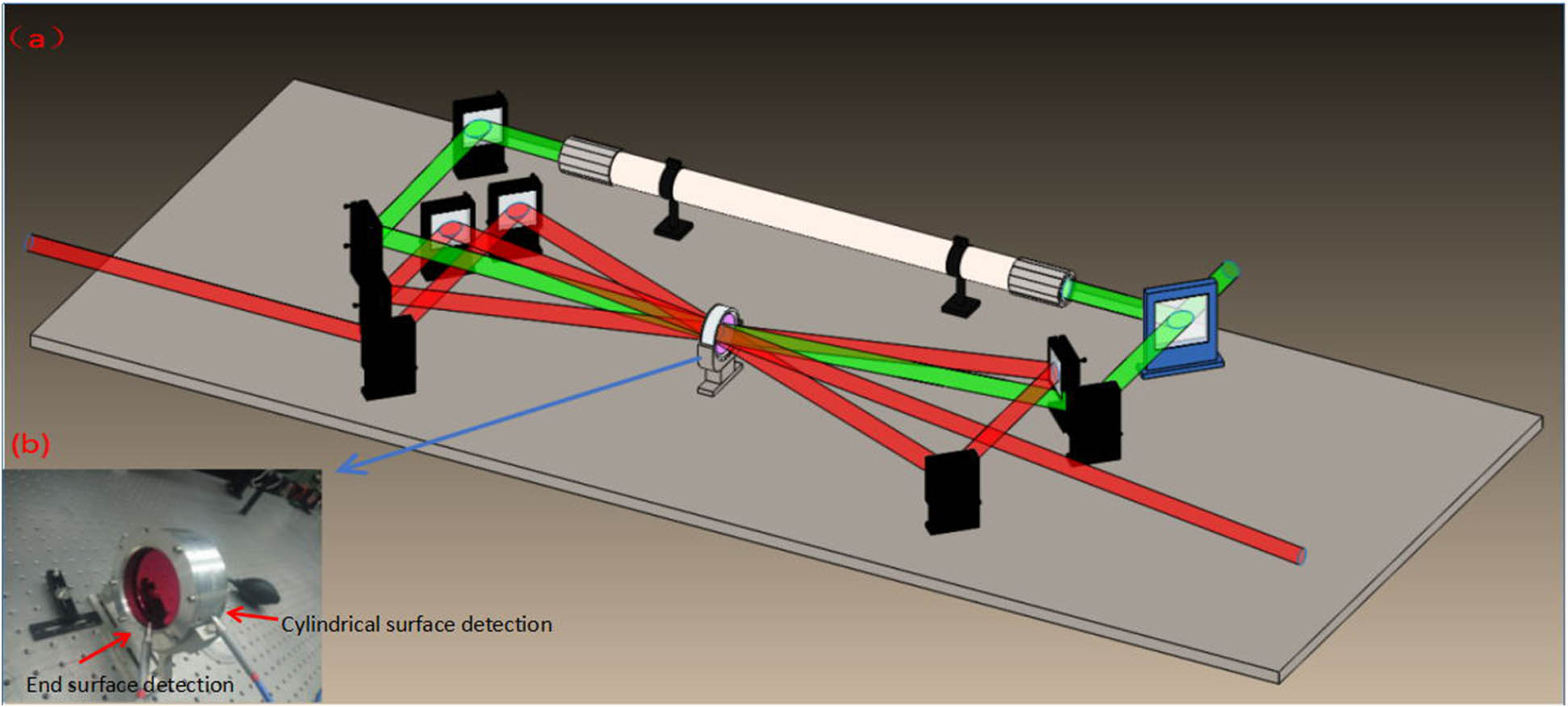
    Figure 1.(a) 100 mm Ti:sapphire amplifier; (b) the cylindrical and end surface spectrum detection method.

    First, we measure the cylindrical surface spectrums under different pump energies without an input signal pulse. The detection method is illustrated in Fig. 1(b). Figure 2 shows the cylindrical surface spectrum when the pump energy is 10 J. We believe this spectrum should be caused by spontaneous emission because it is the same with the Ti:sapphire spontaneous emission spectrum[16,17] in FWHM (140 nm) and the central wavelength (740 nm). Figure 3 displays cylindrical surface spectrums under different pump energies. As shown in Fig. 3, when the pump energy is below 22 J, the spectrum FWHM and central wavelength are 140 and 740 nm, respectively, which should be when the spontaneous emission spectrum and PL has not occurred. From 22 to 29 J, the spectrums gradually narrow and red shift. The FWHM widths are 96, 89, and 61 nm when pump energies are 22, 26.6, and 29 J, respectively, and the corresponding central wavelengths are 756, 772, and 790 nm. We infer that, in this phase, PL occurrs and coexists with amplified spontaneous emission in the Ti:sapphire crystal. When the pump energy reaches 32 J, the FWHM width reduces to 32 nm, and the central wavelength is 792 nm. If the pump energy increases further, the spectrum would not obviously change. By our reckoning, PL has been serious enough to replace amplified spontaneous emission inside the Ti:sapphire.

    Cylindrical surface spectrum under 10 J pump energy.

    Figure 2.Cylindrical surface spectrum under 10 J pump energy.

    Cylindrical surface spectra under different pump energies.

    Figure 3.Cylindrical surface spectra under different pump energies.

    In order to verify that the spectrum we obtain at the cylindrical surface is emitted from the cylindrical surface rather than from the end surface, we place two probes at the cylindrical and end surfaces separately, as shown in Fig. 1(b).

    Figure 4 is the measured spectra from the two surfaces when the pump energy is 43.2 J, and the input signal pulse is absent. As shown in Fig. 4, the spectra from the cylindrical surface and end surface are totally different. The red line is measured from the cylindrical surface, and the black line is from the end surface. Obviously, the red solid line is the PL spectrum centered at 792 nm with an FWHM width of 30 nm. The black line has a double peak structure. The first peak is located at 722 nm, which is close to the central wavelength (740 nm) of the spontaneous emission spectrum in Figs. 2 and 3. The second peak is located at 792 nm, which is the same central wavelength with the PL spectrum in Fig. 3. Thus, we infer that the first peak of the black line in Fig. 4 comes from spontaneous emission, and the second one comes from longitudinal PL, which oscillates between the two end surfaces of the Ti:sapphire crystal. Consequently, the spectrums from the cylindrical and end surfaces are totally different, and the cylindrical surface spectrum would not be influenced by the end surface emission, which means that the method of detecting the cylindrical surface spectrum is effective.

    Comparison of spectra from Ti:sapphire crystal cylindrical and end surfaces.

    Figure 4.Comparison of spectra from Ti:sapphire crystal cylindrical and end surfaces.

    Then, we study the signal spectrums before and after PL. Figure 5 shows signal spectra under different pump energies. The pump energy range is from 23 J at which PL is faint to 62 J at which serious PL occurrs and influences the amplifier output energy. The input signal laser energy is 5.8 J. All of the signal spectrums’ FWHM widths are from 29 to 41 nm, and all of the central wavelengths are 790 nm. As shown in Fig. 5, the signal spectrums’ shapes are identical. From Fig. 5, we can draw a conclusion that PL has little impact on the signal spectrum.

    Ti:sapphire cylindrical surface spectra under different pump energies.

    Figure 5.Ti:sapphire cylindrical surface spectra under different pump energies.

    The relation between pump energy and Ti:sapphire amplifier output energy without cladding has also been studied. Figure 6 shows the variation trend of the Ti:sapphire amplifier output energy as the pump energy increases.

    Ti:sapphire output energy as function of pump energy.

    Figure 6.Ti:sapphire output energy as function of pump energy.

    The input energy of amplifier is set at 5.8 J. If there is no pump laser after the signal laser passes through the Ti:sapphire crystal three times, the output signal laser energy will decrease to about 4.8 J. The amplifier output energy reaches the highest point of 16.9 J when the pump energy is 38 J. As the pump energy increases from 30 to 38 J, the amplifier output energy continues to increase. While in Fig. 3, the PL spectrum becomes apparent and replaces the amplified spontaneous emission spectrum when the pump energy exceeds 32 J. We infer that this is because the pump energy and PL both have impact on output energy. When the pump energy is 32 J, PL has been built up. While PL has less impact on output energy compared to the increase of pump energy, as pump energy reaches 38 J, PL balances the impact of pump energy’s increase on output energy. As pump energy exceeds 38 J, PL plays a major role in output energy compared with pump energy, and the amplifier output energy begins to decrease.

    The influence of PL on the beam profile has also been considered. Figure 7 displays the beam profiles under pump energies of 20 J at which PL has not occurred and 72 J at which PL has become serious enough to influence output energy. The injected seed laser energy is 5.8 J, and the output energies are 10 and 9 J, respectively. As seen in Fig. 7, the intensity distribution is similar in two beam profiles. We believe this is because the pump energy is not high enough to make a difference to the beam profiles.

    Beam profiles under different pump energies. (a) 20 J pump energy; (b) 72 J pump energy.

    Figure 7.Beam profiles under different pump energies. (a) 20 J pump energy; (b) 72 J pump energy.

    In conclusion, the PL spectrum, the relation between PL and amplified spontaneous emission, and the influence of PL on Ti:sapphire amplifier output energy, signal spectrum, and beam profile are systematically studied. The transient process from amplified spontaneous emission to PL in the Ti:sapphire crystal is observed. It is found that the signal pulse can still be amplified in a range even when PL occurrs. Yet, PL has no obvious impact on the amplified output signal spectrum and beam profile.

    References

    [1] G. A. Mourou, G. Koron, W. Sandner, J. L. Collier. ELI–Extreme Light Infrastructure, Science and Technology with Ultra-Intense Lasers(2011).

    [2] V. Chvykov, M. Kalashnikov, K. Osvay. 2015 Conference on Lasers and Electro-Optics Pacific Rim, 27D1_3(2015).

    [3] F. Lureau, S. Laux, O. Casagrande, O. Chalus, P. A. Duvochelle, S. Herriot, G. Matras, C. Radier, L. Boudjemaa, C. Simon-Boisson, R. Dabu, I. Dancus, D. Ursescu. 2015 European Conference on Lasers and Electro-Optics-European Quantum Electronics Conference, CF_P_20(2015).

    [4] C. L. Arnold, F. Brizuela, A. Borot, F. Calegari, D. Charalambidis, T. Cowan, Z. Diveki, P. Dombi, J. Fulop, J. Hebling, C. M. Heyl, A. L’Huillier, D. A. Jaroszynski, P. Johnsson, V. Malka, M. Kalashnikov, M. Kaluza, R. Lopez-Martens, M. Nisoli, K. Osvay, G. Paulus, F. Quéré, E. Racz, A. Rouzée, P. Rudawski, C. Spindloe, M. Tolley, P. Tzallas, M. Vrakking. CLEO: 2013, OSA Technical Digest, JTh2A.13(2013).

    [5] S. Gales, N. V. Zamfir. AIP Conf. Proc., 1645, 201(2015).

    [6] G. Chériaux, F. Giambruno, A. Fréneaux. AIP Conf. Proc., 1462, 78(2012).

    [7] C. H. Gomez, S. P. Blake, O. Chekhlov, R. J. Clarke, A. M. Dunne, M. Galimberti, S. Hancock, R. Heathcote, P. Holligan, A. Lyachev, P. Matousek, I. O. Musgrave, D. Neely, P. A. Norreys, I. Ross, Y. Tang, T. B. Winstone, B. E. Wyborn. J. Phys.: Conf. Series, 244, 032006(2010).

    [8] V. V. Lozhkarev, G. I. Freidman, V. N. Ginzburg, E. V. Katin, E. A. Khazanov, A. V. Kirsanov, G. A. Luchinin, A. N. Mal’shakov, M. A. Martyanov, O. V. Palashov, A. K. Poteomkin, A. M. Sergeev, A. A. Shaykin, I. V. Yakovlev. Laser Phys. Lett., 4, 421(2007).

    [9] M. P. Kalashnikov, H. Cao, K. Osvay, V. Chvykov, N. Khodakovskiy, R. S. Nagymihaly. Conference on Lasers and Electro-Optics, SM1M.2(2016).

    [10] Y. Zhang, X. Wei, M. Li, J. Zheng, J. Zhang, N. Xie, Z. Wang, M. Wang, X. Yan, X. Jiang. Laser Phys., 23, 055802(2013).

    [11] M. E. Graham, B. I. Davis, D. V. Keller. Appl. Opt., 4, 613(1965).

    [12] V. V. Chvykov, V. P. Yanovsky, S. W. Bahk, G. Kalintchenko, G. Morou. Conference on Lasers and Electro-Optics/Quantum Electronics and Lasers Science Conference, Technical Digest, CWA34(2003).

    [13] V. V. Chvykov, M. Kalashnikov, K. Osvay. Advanced Solid State Lasers, ATu2A.39(2015).

    [14] Y. Chu, Z. Gan, X. Liang, L. Yu, X. Lu, C. Wang, X. Wang, L. Xu, H. Lu, D. Yin, Y. Leng, R. Li, Z. Xu. Opt. Lett., 40, 21(2015).

    [15] X. Liang, Y. Leng, C. Wang, C. Li, L. Lin, B. Zhao, Y. Jiang, X. Lu, M. Hu, C. Zhang, H. Lu, D. Yin, Y. Jiang, X. Lu, H. Wei, J. Zhu, R. Li, Z. Xu. Opt. Express, 15, 23(2007).

    [16] X. Zhang, Y. Chai, C. Qi. Chin. J. Lumin., 11, 4(1990).

    [17] J. Zhang, Z. Sun, Z. Wang, J. Si, J. Wang, Y. Hang, J. Xu. J. Synth. Cryst., 34, 4(2005).

    Zutao Fan, Zebiao Gan, Xiaoyan Liang, Lianghong Yu, Wenqi Li, Zhen Guo, Xiaolong Yuan, He Cao, Pei Huang, Ruxin Li, Zhizhan Xu. Parasitic lasing in large aperture Ti:sapphire chirped pulse amplifier[J]. Chinese Optics Letters, 2017, 15(6): 061401
    Download Citation