• Chinese Optics Letters
  • Vol. 21, Issue 2, 023603 (2023)
Chenxi Pu1, Zhuo Wang1, Shulin Sun2, Lei Zhou1、*, and Qiong He1、**
Author Affiliations
  • 1State Key Laboratory of Surface Physics and Department of Physics, Key Laboratory of Micro and Nano Photonic Structures (Ministry of Education), Fudan University, Shanghai 200433, China
  • 2Shanghai Engineering Research Centre of Ultra-Precision Optical Manufacturing, Green Photonics and Department of Optical Science and Engineering, Fudan University, Shanghai 200433, China
  • show less
    DOI: 10.3788/COL202321.023603 Cite this Article Set citation alerts
    Chenxi Pu, Zhuo Wang, Shulin Sun, Lei Zhou, Qiong He. Transmissive angle-multiplexed meta-polarizer based on a multilayer metasurface[J]. Chinese Optics Letters, 2023, 21(2): 023603 Copy Citation Text show less
    Schematic of transmissive angle-multiplexed meta-polarizer based on multilayered isotropic metasurfaces under (a) normal and (b) oblique incidence. (c) Schematic of meta-atom design. Geometrical parameters of meta-atom: la = 7.2 mm, wa = 1.8 mm, unit cell period P = 7.5 mm, thickness of metallic film t = 0.035 mm, and thickness of dielectric layer ts = 1 mm.
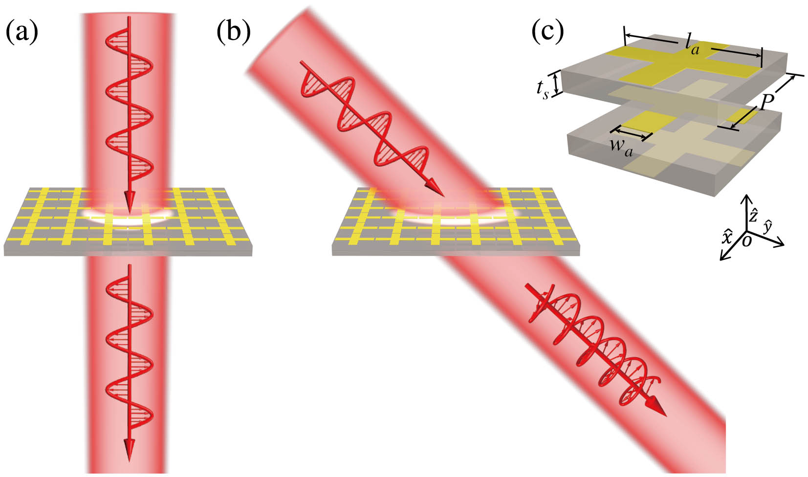
    Fig. 1. Schematic of transmissive angle-multiplexed meta-polarizer based on multilayered isotropic metasurfaces under (a) normal and (b) oblique incidence. (c) Schematic of meta-atom design. Geometrical parameters of meta-atom: la = 7.2 mm, wa = 1.8 mm, unit cell period P = 7.5 mm, thickness of metallic film t = 0.035 mm, and thickness of dielectric layer ts = 1 mm.
    FDTD-simulated and TMM calculated transmittance and transmission-phase spectra of our angle-multiplexed meta-polarizer for TE and TM polarized wave at the incident angle of (a), (b) 0° and (c), (d) 50°, respectively. The dashed black line indicates the working frequency of our meta-device at 12.36 GHz. (e) The variation of ellipticity and polarization angle of the transmitted wave with incident angle. (f) The variation of transmittance of TE and TM polarized waves with incident angle at 12.36 GHz. The insets of (f) depict polarization states of transmitted wave at 0°, 43°, and 65° incidence, respectively.
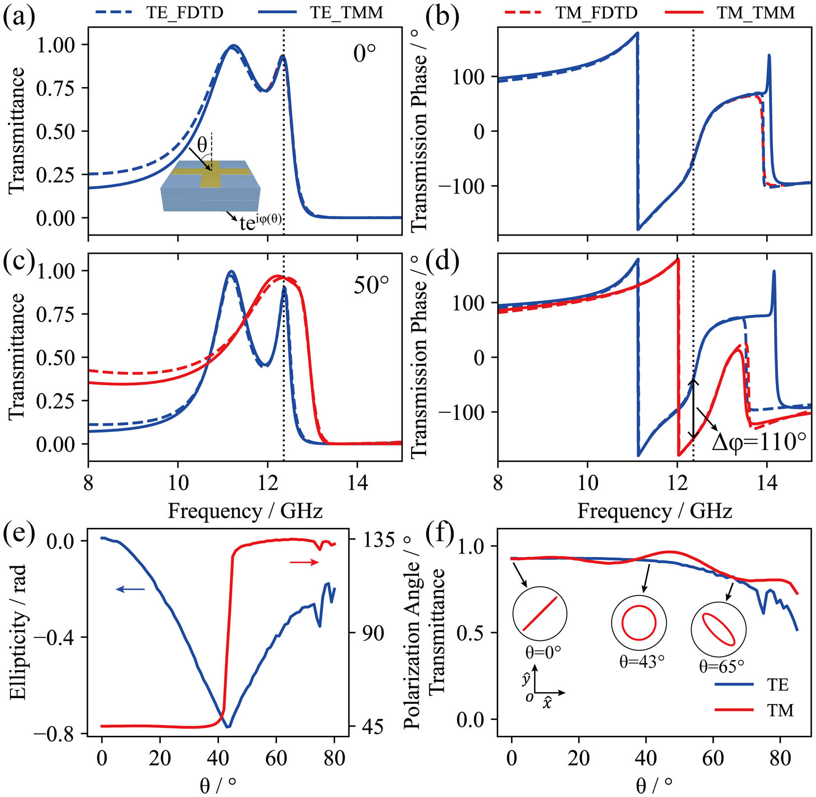
    Fig. 2. FDTD-simulated and TMM calculated transmittance and transmission-phase spectra of our angle-multiplexed meta-polarizer for TE and TM polarized wave at the incident angle of (a), (b) 0° and (c), (d) 50°, respectively. The dashed black line indicates the working frequency of our meta-device at 12.36 GHz. (e) The variation of ellipticity and polarization angle of the transmitted wave with incident angle. (f) The variation of transmittance of TE and TM polarized waves with incident angle at 12.36 GHz. The insets of (f) depict polarization states of transmitted wave at 0°, 43°, and 65° incidence, respectively.
    (a) Spectra of transmittance and (b) transmission-phase for an individual meta-layer consisting of a periodical array of resonators placed on a 1-mm-thick dielectric layer [see inset of (a)] under two special incident angles (0° and 50°).
    Fig. 3. (a) Spectra of transmittance and (b) transmission-phase for an individual meta-layer consisting of a periodical array of resonators placed on a 1-mm-thick dielectric layer [see inset of (a)] under two special incident angles (0° and 50°).
    FDTD-simulated and CMT calculated spectra of (a) transmittance and (b) transmission-phase of our meta-design at the incident angle of 50°. The variation of (c) resonant frequency and (d) radiation damping rate of two resonant modes with incident angle. The distribution of Re(Ey)/|E0| on the center y–z plane inside a meta-atom of (e) antisymmetrical and (f) symmetrical modes retrieved by CMT under normal illumination with TE-polarized plane wave, with |E0| being the electric field intensity of the input wave. The atom is placed parallel to the xoy plane, and the patterns of Re(Ex)/|E0| for the TM-polarized plane wave are identical. Distribution of reflectance of individual top meta-layer [see inset of Fig. 3(a)] as a function of incident angle and frequency under the illumination of (g) TE and (h) TM polarized waves, respectively.
    Fig. 4. FDTD-simulated and CMT calculated spectra of (a) transmittance and (b) transmission-phase of our meta-design at the incident angle of 50°. The variation of (c) resonant frequency and (d) radiation damping rate of two resonant modes with incident angle. The distribution of Re(Ey)/|E0| on the center yz plane inside a meta-atom of (e) antisymmetrical and (f) symmetrical modes retrieved by CMT under normal illumination with TE-polarized plane wave, with |E0| being the electric field intensity of the input wave. The atom is placed parallel to the xoy plane, and the patterns of Re(Ex)/|E0| for the TM-polarized plane wave are identical. Distribution of reflectance of individual top meta-layer [see inset of Fig. 3(a)] as a function of incident angle and frequency under the illumination of (g) TE and (h) TM polarized waves, respectively.
    (a) Picture of fabricated sample. (b) Schematic of realistic meta-atom with εadhesive =4.2 (1 + 0.025i), tadhesive = 0.18 mm, ts = 0.93 mm, wa = 1.8 mm. Measured and FDTD-simulated (c) transmittance and (d) Δφ for TE and TM polarizations as a function of the incident angle at the working frequency of 11.7 GHz. (e) Measured and (f) simulated f-θ phase diagram of Δφ.
    Fig. 5. (a) Picture of fabricated sample. (b) Schematic of realistic meta-atom with εadhesive =4.2 (1 + 0.025i), tadhesive = 0.18 mm, ts = 0.93 mm, wa = 1.8 mm. Measured and FDTD-simulated (c) transmittance and (d) Δφ for TE and TM polarizations as a function of the incident angle at the working frequency of 11.7 GHz. (e) Measured and (f) simulated f-θ phase diagram of Δφ.
    Performance optimization of our meta-polarizer performance. (a) FDTD-simulated transmittance spectra for the meta-polarizer with different wa under normal incidence. (b) FDTD-simulated transmittance spectra for the meta-polarizer with different degrees of symmetry under normal incidence with wa = 2.3 mm. FDTD-simulated (c) transmittance and (d) transmission-phase spectra for the optimized meta-polarizer with wa = 2.3 mm in a symmetric configuration at the incident angle of 47°. The other optimized geometrical parameters are consistent with experiment. FDTD-simulated (e) transmittance and (f) transmission-phase spectra for the optimized meta-polarizer without the adhesive layer at the incident angle of 41°. The optimized cross width wa = 1.5 mm.
    Fig. 6. Performance optimization of our meta-polarizer performance. (a) FDTD-simulated transmittance spectra for the meta-polarizer with different wa under normal incidence. (b) FDTD-simulated transmittance spectra for the meta-polarizer with different degrees of symmetry under normal incidence with wa = 2.3 mm. FDTD-simulated (c) transmittance and (d) transmission-phase spectra for the optimized meta-polarizer with wa = 2.3 mm in a symmetric configuration at the incident angle of 47°. The other optimized geometrical parameters are consistent with experiment. FDTD-simulated (e) transmittance and (f) transmission-phase spectra for the optimized meta-polarizer without the adhesive layer at the incident angle of 41°. The optimized cross width wa = 1.5 mm.
    Chenxi Pu, Zhuo Wang, Shulin Sun, Lei Zhou, Qiong He. Transmissive angle-multiplexed meta-polarizer based on a multilayer metasurface[J]. Chinese Optics Letters, 2023, 21(2): 023603
    Download Citation