
Zongdan Jiang, Peili Li, Guangyue Xu. Terahertz Wave 4-2 Encoder Based on Photonic Crystal[J]. Chinese Journal of Lasers, 2021, 48(20): 2014002
- Chinese Journal of Lasers
- Vol. 48, Issue 20, 2014002 (2021)
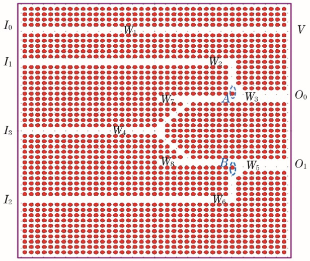
Fig. 1. Structure of the terahertz wave 4-2 encoder based on photonic crystal
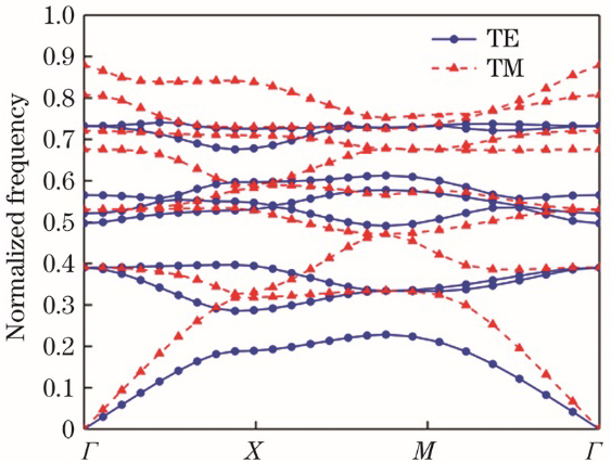
Fig. 2. TE and TM mode forbidden band diagrams of photonic crystal
Fig. 3. Encoder performance when I0=1, I1=0, I2=0, I3=0. (a) Steady-state filed intensity distribution; (b) time-domain steady-state diagram
Fig. 4. Encoder performance when I0=0, I1=1, I2=0, I3=0. (a) Steady-state filed intensity distribution; (b) time-domain steady-state diagram
Fig. 5. Encoder performance when I0=0, I1=0, I2=1, I3=0. (a) Steady-state filed intensity distribution; (b) time-domain steady-state diagram
Fig. 6. Encoder performance when I0=0, I1=0, I2=0, I3=1. (a) Steady-state filed intensity distribution; (b) time-domain steady-state diagram
Fig. 7. Relationship between transmittance and wavelength
Fig. 8. Relationship between contrast radio and wavelength
Fig. 9. Influence of short cavity waveguide with different length on beam splitting effect
Fig. 10. Output of the encoder without introduction of dielectric column
| ||||||||||||||||||||||||||||||||||||
Table 1. Truth table of the terahertz wave 4-2 encoder based on photonic crystal
| |||||||||||||||||||||||||||||||||||||||||||||||||||
Table 2. Peformance parameters of the terahertz wave 4-2 encoder based on photonic crystal

Set citation alerts for the article
Please enter your email address
© Copyright 2018-2021 | Chinese Laser Press. All Rights Reserved 沪ICP备15018463号-20