• Chinese Optics Letters
  • Vol. 13, Issue Suppl., S21501 (2015)
Yuzhou Liu and Bin Zhao*
Author Affiliations
  • Department of Instrumentation, School of Mechanical Science and Engineering, Huazhong University of Science and Technology, Wuhan 430074, China
  • show less
    DOI: 10.3788/COL201513.S21501 Cite this Article Set citation alerts
    Yuzhou Liu, Bin Zhao. Improving the accuracy of the phase difference in a high-frequency range finder[J]. Chinese Optics Letters, 2015, 13(Suppl.): S21501 Copy Citation Text show less

    Abstract

    We present a phase difference range system with about 1.5 GHz of modulation frequencies. To reduce the phase difference drift, the high-frequency signals are synthesized by digital fractional phase-locked loops, and a differential measurement method is employed by introducing an optical switch. In order to eliminate the electrical crosstalk, a photoelectric modulator working as a mixer is used. The experimental results show that the distance error of the proposed system is within ±0.04 mm and the phase difference error is less than 0.15°.

    Laser range finders that employ time-of-flight techniques can be divided into three categories: pulsed techniques[1], the frequency modulation continuous wave method[2], and the phase difference method[3]. The last method is well adapted to a medium-range distance measurement (from tens of centimeters to tens of meters), and allows the distance to be evaluated with a high resolution of millimeters[4]. Therefore, it has attracted considerable research interest in a variety of fields, such as shape measurements of large-scale structures[5], robot navigation[6], and object recognition[7]. It is an effective method to increase the modulation frequency for improving the distance resolution. However, in a high-frequency phase difference range finder, the accuracy of the distance measurement is limited by the electrical crosstalk[8] and the phase difference drift. In this Letter, the aim of the work is to improve the performance of the high-frequency phase difference range finder by eliminating the crosstalk and reducing the phase difference drift.

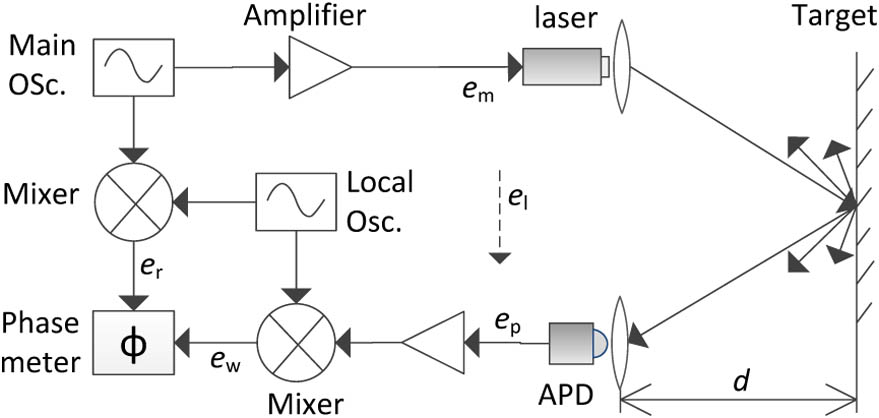
    The principle of the phase difference method is shown in Fig. 1. The transmitted optical power of the laser is modulated with a sine signal generated by the main oscillator at the frequency f. Having been reflected by the diffusing surface of the target, the laser beam is partially collected by an avalanche photodiode (APD) through a focusing lens. The phase difference ϕ between em and ep contains the information on the distance (d). Precisely measuring the phase difference at a high frequency is quite difficult; thus, a heterodyne technique is used. The photoelectric signal as well as the signal from main oscillator is mixed with a local oscillator in order to measure the phase difference between the two intermediate frequency signals, the reference signal er, and the work signal ew. The distance to be measured is deduced from the phase difference. d=c2f·ϕ2π,where c is the celerity of light. Equation (1) indicates that the accuracy of the distance is directly determined by the phase difference accuracy.

    Block diagram of the phase difference laser range finder.

    Figure 1.Block diagram of the phase difference laser range finder.

    The resolution of the distance is given by δd=c4πfδϕ.

    It is difficult to improve the resolution of the phase difference δϕ by more than 0.01°, so it is an effective method to increase the modulation frequency for improving the distance resolution. For example, with a phase measurement resolution of 0.1° and a 100 MHz sinus modulation frequency, we obtain a distance resolution close to 0.4 mm. However, if the modulation frequency is increased, the electrical crosstalk and the phase drift limit the accuracy of the phase difference.

    First, we analyze the influence of the electrical crosstalk on the phase difference in the following. The error expression given illustrates that the crosstalk will yield a periodic phase difference errors versus the distance d.

    When the photoelectric signal (ep) output from the APD and the modulation signal (em) of the laser have the same frequency, the crosstalk signal, or the leakage signal (el), which arises from the modulation signal, is vectorially superimposed on the photoelectric signal. For a given distance d, the modulation signal and the photoelectric and the leakage signals are given by em=Asin(2πft),ep=Bsin(2πft+α),el=Csin(2πft+β),where α is the theoretical phase difference that contains the distance information, and β is the phase difference between the leakage and the modulation signals.

    Then, the actual measured signal is given by ea=ep+el=Dsin(2πft+γ),where γ is the actual phase difference. It can be obtained with the relationship: γ=arctan(C/B)sinβ+sinα(C/B)cosβ+cosα.

    Using Eqs. (1) and (7), the phase difference error caused by the electrical crosstalk can be expressed as Δϕ=γα=arctan(C/B)sin(βα)1+(C/B)cos(βα)=arctan(C/B)sin(β4πfd/c)1+(C/B)cos(β4πfd/c).

    Therefore Δϕ is given as a periodic function of the distance d, and the period, which is equal to c/(2f), is a half wavelength of the modulation signal. The distance measurement error corresponding to Δϕ is: Δd=c4πfarctan(C/B)sin(β4πfd/c)1+(C/B)cos(β4πfd/c).

    The influences of the crosstalk on the distance as derived from Eq. (9) are shown in Fig. 2 for β=50°, C/B=1/40, and f=1.5GHz. Notice that the error curve is similar to the sine curve, and in the figure, we assume C/B is independent of d. To verify these, the range system described in Fig. 1 has been evaluated by comparing the distance measurement results with the displacements of a laser interferometer. The distance errors obtained at a modulation frequency of 1.5 GHz are shown in Fig. 3, and the actual curve can be fitted to the following equation: Δd=c4πf[a(d2+b)sin(θ4πfdc)],where a, b, and θ are constants.

    The influences of the crosstalk on the phase difference and distance, for β=50°, C/B=1/40, and f=1.5 GHz.

    Figure 2.The influences of the crosstalk on the phase difference and distance, for β=50°, C/B=1/40, and f=1.5GHz.

    The actual periodic errors of the range system.

    Figure 3.The actual periodic errors of the range system.

    It seems that there are some differences between Eqs. (9) and (10), but the slight discrepancy will be resolved by expanding Eq. (9) according to McLaughlin formula. Because the ratio C/B is small, the first-order McLaughlin expansion related to (C/B) is Δd=c4πfCBsin(β4πfdc).

    In Eq. (10), if we ignore b, which indicates that the amplitude of the periodic error at the zero position is not zero and its value is dependent on the choice of the zero position, Eq. (10) is coincident with Eq. (11). The modulator and detector positions are unchanged in the range finder, so β and C are constant for a given value of f, but B is proportional to 1/d2. With the varying of d, the errors of the phase difference and the distance will reach their maximum values when β4πfd/c=2nπ±π/2 (n is an integer). To limit the maximum error of the phase difference to 0.1°, the ratio of B/C must be 55 dB, and this condition is difficult to satisfy with the shielding techniques in a high-frequency range finder.

    Using an APD as an optoelectronic mixer can eliminate the periodic error[8], but the phase delay in the diode output increases with a decrease in the incident intensity. This characteristic leads to errors in distance measurements, as the optical intensity come of the diode varies with the distance and with the material of the target. In our system, the periodic error is suppressed by using a Mach–Zehnder modulator as a mixer before the detector.

    The phase drift may lead to irregular phase difference errors, which are still rather difficult to implement. These are mainly caused by three factors: frequency drift[9], the impedance drift, and the noise of the circuits.

    The condition of conjugate impedance matching for every basic power transportation unit of the circuits not only enables maximum power transportation but also eliminates phase shift when the power is transported from the source to the load. This is due to the fact that the resulting impedance contains the only pure resistance in the entire source-load circuit loop under the condition of conjugate impedance matching. In an unmatched case, the phase shift in the circuits is a function of the impedance and frequency. If a perfect symmetry is obtained between the reference signal and the work signal circuits, it can be supposed that the main oscillator frequency drift or the local oscillator frequency drift balances the drift of the other one. In this case, no error is present, as the reference signal channel and the work signal channel are identical. However, it is difficult to fulfill exact matching and symmetry in actual circuit boards. Thus, the frequency or the impedance drift produce a phase difference drift so as to impact the performance of the range finder. A phase difference drift obtained with the range system described in Fig. 1 at a modulation frequency of 1.5 GHz is shown in Fig. 4. It shows that the phase difference drift is about 1° for 200 s.

    Phase difference drift.

    Figure 4.Phase difference drift.

    In actual oscillators, the circuit and system noise gives rise to phase noise and random jitter. The phase difference drift caused by the noise can be reduced by rejecting the common mode noise using a differential pair runner, eliminating spuriousness by filtering, and calculating the phase difference using the multi-cycle cross-correlation method[10].

    The block diagram of our proposed phase difference range finder is shown in Fig. 5. The system is composed of three main units: modulation unit, an optics unit, and a processing unit.

    Block diagram of the proposed phase difference laser range finder.

    Figure 5.Block diagram of the proposed phase difference laser range finder.

    The modulation unit produces the sinusoidal modulation signal. The main oscillator synthesizes 1.4985 and 1.4835 GHz signals sequentially with digital fractional phase-locked loops (we used the ADF4350 wideband synthesizer) from an analog device. The first frequency led to a 2.8 μm distance resolution with a phase measurement resolution of 0.01°, while the unambiguous range with respect to the difference of the two frequencies is 10 m. The intensity of the laser beam of the 1550 nm laser with a power of 40 mW is modulated by a Mach–Zehnder modulator. Experiments show that if the main oscillator is independent to the local oscillator, a large drift in the intermediate frequency may occur. The local oscillator in the processing unit has the same configuration as the main oscillator, but their frequencies are different. To reduce the frequency drift of the intermediate frequency signals, both oscillators are driven by the same temperature-compensated crystal.

    The emission and detection parts that are associated with the optical components form the optics unit. The distance to be measured is indicated by the zero position and the target position. The round-trip time of the modulated beam between the zero position and the target position is proportional to the phase delay of the wave. But a large error occurs when the phase delay is measured directly due to the phase difference drift, which is caused by frequency drift and the impedance drift of the circuits. In the optics unit, a differential measurement method is used to eliminate the phase difference drift by introducing the optical switch. The optical switch and the oscillators are controlled by a single-chip microcomputer, which is not shown in Fig. 1. First, the light enters into port 1 of the optical switch, passes through the circulator and collimator, reaches the target, and then is reflected into the circulator by the same path. It is finally fed into modulator 2 by the coupler. The phase difference between the final signal that is fed into modulator 2 and the original electrical modulation signal, which is denoted by ϕ1, can be calculated by the processing unit. Second, when the controller turns on port 2 and turns off port 1 of the optical switch, the light with the same modulated frequency is directly coupled into modulator 2 by the coupler. The phase difference between the signal that is fed into modulator 2 again and the original electrical modulation signal is measured and denoted by ϕ2. Although both ϕ1 and ϕ2 are involved in the phase difference drift, the drift is removed in their difference because the switching time of the switch is only a few milliseconds. It should be noted that ϕ1ϕ2 includes not only the phase delay that comes from the distance d, but also the additional phase delay generated by the light transmission through the fiber, circulator, and collimator. This problem can be solved by calibrating the zero position. In the calibration procedure, after putting the target to the zero position, we obtain a phase difference ϕ01 when port 1 of the optical switch is switched on and a phase difference ϕ02 when port 2 is on. The additional phase delay is calculated by ϕ01ϕ02. Therefore, the phase difference, which is proportional to the distance, is ϕ=(ϕ1ϕ2)(ϕ01ϕ02).

    In photoelectric modulator 2, the light is modulated again by sine signals generated by the local oscillator. That means that modulator 2 worked as a mixer. The signal frequency of the local oscillator is always 1 MHz less than that of the main oscillator, so the frequency of the photoelectric signal output from the photodetector is different from the signal frequency of the main oscillator, and the crosstalk is eliminated.

    The phase difference estimation and the distance calculation are realized by the processing unit. Precisely measuring the phase difference at about 1.5 GHz is quite difficult. The heterodyne technique that preserves the phase difference versus the distance allows the phase difference to be measured at an intermediate frequency. One intermediate frequency signal has been obtained from the photodetector. Another reference signal at 1 MHz is obtained by mixing the signals that come directly from the main oscillator and the local oscillator. Both intermediate frequency signals are sampled synchronously by a dual-channel 48 MHz analog-to-digital converter. Finally, the phase difference is estimated using a correlation analysis, and the distances are calculated by the computer.

    The phase difference drift has been examined when the modulation frequency and the distance remain unchanged. The results are shown in Fig. 6. We can see that the variation of the phase difference is about 0.15°, which corresponds to a distance error of 0.04 mm. The rapid random variation of the phase difference is mainly caused by the detector and circuits’ noise.

    Phase difference drift of the modified system.

    Figure 6.Phase difference drift of the modified system.

    Figure 7 shows the experimental setup. A corner cube and a reflector are located on a moving trestle. The displacement of the moving trestle is measured using both the laser interferometer Agilent 5529A and the range finder. The ranger finder is evaluated by regarding the laser interferometer as a reference standard because the accuracy of the laser interferometer is much better than that of the ranger finder. The distance error of the range finder is shown in Fig. 8. It shows that there are no periodic errors and that the maximum error of the range system is about 0.04 mm, which corresponds to the 0.15° maximum phase difference error.

    Experimental setup.

    Figure 7.Experimental setup.

    Distance error of the range finder.

    Figure 8.Distance error of the range finder.

    In conclusion, based on the phase difference range finder, a high-frequency range system for improving the accuracy of the phase difference is presented. The analyses and experiments demonstrate that the periodic errors with a period of a half wavelength of the modulation signal caused by the electrical crosstalk and the phase difference drift produced by the frequency and impedance drift will give rise to notable phase difference errors. In our system for reducing the phase difference drift, both the main oscillator and the local oscillator are synthesized by digital fractional phase-locked loops, and a differential measurement method is used by introducing the optical switch. To eliminate the electrical crosstalk between the photoelectric and the modulation signals, a photoelectric modulator is used as a mixer. Compared with the distance value of the laser interferometer, the error of the proposed range system is within ±0.04mm and the phase difference error is less than 0.15°.

    Yuzhou Liu, Bin Zhao. Improving the accuracy of the phase difference in a high-frequency range finder[J]. Chinese Optics Letters, 2015, 13(Suppl.): S21501
    Download Citation