• High Power Laser Science and Engineering
  • Vol. 7, Issue 3, 03000e47 (2019)
Zhengru Guo1, Qiang Hao1、†, Junsong Peng2, and Heping Zeng1、2
Author Affiliations
  • 1Shanghai Key Laboratory of Modern Optical System, and Engineering Research Center of Optical Instrument and System, Ministry of Education, School of Optical Electrical and Computer Engineering, University of Shanghai for Science and Technology, Shanghai 200093, China
  • 2State Key Laboratory of Precision Spectroscopy, East China Normal University, Shanghai 200062, China
  • show less
    DOI: 10.1017/hpl.2019.29 Cite this Article Set citation alerts
    Zhengru Guo, Qiang Hao, Junsong Peng, Heping Zeng. Environmentally stable Er-fiber mode-locked pulse generation and amplification by spectrally filtered and phase-biased nonlinear amplifying long-loop mirror[J]. High Power Laser Science and Engineering, 2019, 7(3): 03000e47 Copy Citation Text show less
    Results of numerical simulations without the intracavity bandpass filter. (a) Temporal and (b) spectral evolution of the pulse. (c) Temporal shape (blue curve) and phase (red curve) at the 600th round trip. (d) Spectral shape (blue curve) and phase (red curve) at the 600th round trip.
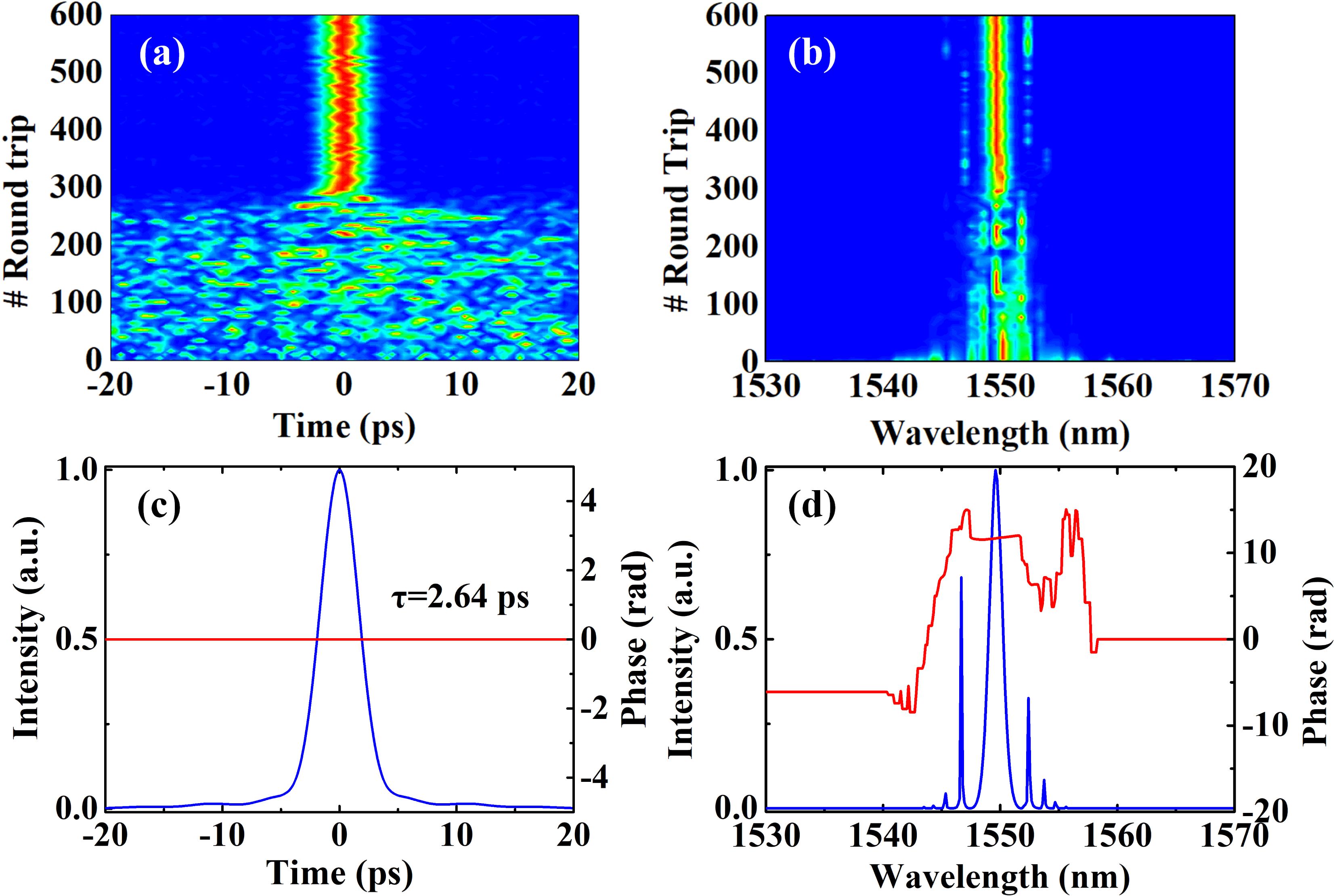
    Fig. 1. Results of numerical simulations without the intracavity bandpass filter. (a) Temporal and (b) spectral evolution of the pulse. (c) Temporal shape (blue curve) and phase (red curve) at the 600th round trip. (d) Spectral shape (blue curve) and phase (red curve) at the 600th round trip.
    Results of numerical simulations with the intracavity bandpass filter. (a) Characteristics of the output pulses versus the bandwidth of the incorporated bandpass filter. (b) Evolution of the output pulses and (c) steady output spectrum and phase of the simulated oscillator with a 2-nm bandpass filter.
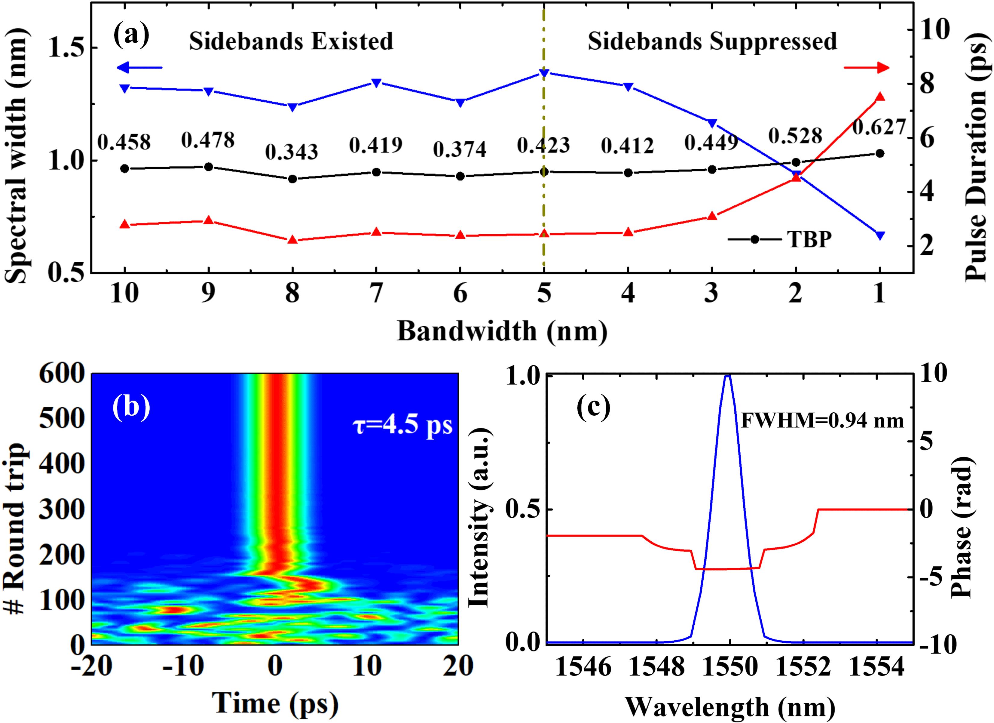
    Fig. 2. Results of numerical simulations with the intracavity bandpass filter. (a) Characteristics of the output pulses versus the bandwidth of the incorporated bandpass filter. (b) Evolution of the output pulses and (c) steady output spectrum and phase of the simulated oscillator with a 2-nm bandpass filter.
    (a) Schematic of the experimental oscillator. (b) Pulse train at a repetition rate of 1.84 MHz. (c) Radio-frequency spectra of the obtained pulses. LD: laser diode; WDM: wavelength division multiplexer; BP: bandpass filter; OFM: optical fiber mirror.
    Fig. 3. (a) Schematic of the experimental oscillator. (b) Pulse train at a repetition rate of 1.84 MHz. (c) Radio-frequency spectra of the obtained pulses. LD: laser diode; WDM: wavelength division multiplexer; BP: bandpass filter; OFM: optical fiber mirror.
    Comparison of the spectra with (blue curves) and without (red curves) the bandpass filter when the oscillator operates in the (a) multiple-pulse and (b) single-pulse operation regimes. For a better comparison, the blue curves are red-shifted by 6.4 nm.
    Fig. 4. Comparison of the spectra with (blue curves) and without (red curves) the bandpass filter when the oscillator operates in the (a) multiple-pulse and (b) single-pulse operation regimes. For a better comparison, the blue curves are red-shifted by 6.4 nm.
    (a) Schematic configuration of the pre-amplifier. ISO: isolator; PBS: polarized beam splitter; ESF: Er-doped single-mode fiber; FRM: Faraday rotation mirror. (b) Spectral profiles when the intracavity bandpass filter in the laser oscillator is activated (blue curve) or removed (red curve). (c) Autocorrelation trace measured by the PulseCheck.
    Fig. 5. (a) Schematic configuration of the pre-amplifier. ISO: isolator; PBS: polarized beam splitter; ESF: Er-doped single-mode fiber; FRM: Faraday rotation mirror. (b) Spectral profiles when the intracavity bandpass filter in the laser oscillator is activated (blue curve) or removed (red curve). (c) Autocorrelation trace measured by the PulseCheck.
    (a) Slope efficiency of the double-cladding amplifier. Inset: autocorrelation trace of the amplified pulses. (b) Average power stability.
    Fig. 6. (a) Slope efficiency of the double-cladding amplifier. Inset: autocorrelation trace of the amplified pulses. (b) Average power stability.
    Output power of the laser system in an incubator as the temperature changes.
    Fig. 7. Output power of the laser system in an incubator as the temperature changes.
    ParametersLengthGain coefficientDispersion parametersBandwidth
    Gain fiber 2 m 1.8 dB/m GVD: $30.2~\text{ps}^{2}/\text{km}$;$1.6~\text{W}^{-1}\cdot \text{km}^{-1}$40 nm
    TOD: $0.021~\text{ps}^{3}/\text{km}$
    PM 1550 fiber 50 m 0 GVD: $-22.8~\text{ps}^{2}/\text{km}$;$1.6~\text{W}^{-1}\cdot \text{km}^{-1}$/
    TOD: $0.132~\text{ps}^{3}/\text{km}$
    SA 1 m / //
    Bandpass filter 1 m / // Variable
    Output coupler 1 m / /$1.6~\text{W}^{-1}\cdot \text{km}^{-1}$/
    Table 1. Schematic configuration of the simulated laser oscillator and the related parameters.
    Zhengru Guo, Qiang Hao, Junsong Peng, Heping Zeng. Environmentally stable Er-fiber mode-locked pulse generation and amplification by spectrally filtered and phase-biased nonlinear amplifying long-loop mirror[J]. High Power Laser Science and Engineering, 2019, 7(3): 03000e47
    Download Citation