Author Affiliations
1Centre Lasers Intenses et Applications (CELIA), Université de Bordeaux–CNRS–CEA, Talence cedex, France2ENEA, Fusion and Technology for Nuclear Safety and Security Department, C.R. Frascati, Frascati, Italy3AWE, Aldermaston, Reading, UK4Centre for Inertial Fusion Studies, Blackett Laboratory, Imperial College London, London, UK5Istituto Nazionale di Ottica, Consiglio Nazionale delle Ricerche (CNR-INO), Pisa, Italy6ETSIAE Universidad Politecnica de Madrid, Madrid, Spain7GSI-Helmholtzzentrum für Schwerionenforschung GmbH, Darmstadt, Germany8Laboratoire pour l’Utilisation des Lasers Intenses (LULI), CNRS–Ecole Polytechnique, Palaiseau cedex, France9ALP, Le Barp, France and CEA/DAM Île de France, Bruyères le Châtel, Arpajon cedex, France10Instituto Fusión Nuclear “Guillermo Velarde” (IFN-GV), Universidad Politecnica de Madrid, Madrid, Spain11Central Laser Facility, STFC Rutherford Appleton Laboratory, Harwell Oxford, Oxfordshire, UK12Institute of Plasma Physics and Lasers, University Research and Innovation Centre, Hellenic Mediterranean University, Rethymno, Crete, Greece13Department of Electronic Engineering, School of Engineering, Hellenic Mediterranean University, Chania, Crete, Greece14Extreme Light Infrastructure ERIC, ELI-Beamlines Facility, Dolní Břežany, Czech Republic15Centro de Laseres Pulsados (CLPU), Parque Cientifico, Villamayor, Salamanca, Spainshow less
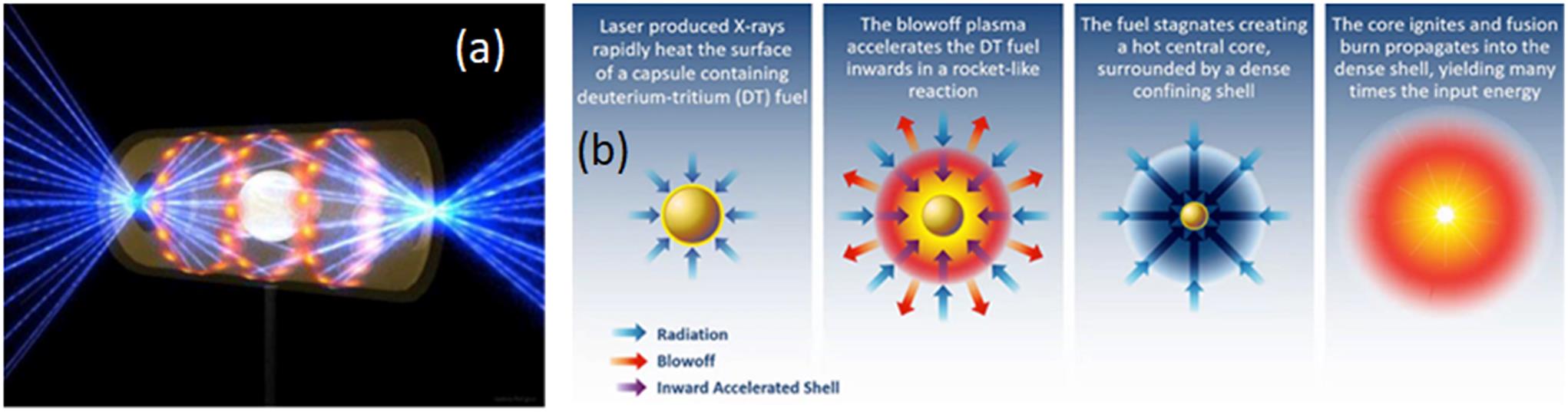
Fig. 1. (a) Laser beams irradiating the hohlraum enclosing and the DT-filled capsule at the NIF (image courtesy of the LLNL). (b) Sequence of four stages of the ICF process in the indirect-drive scheme: (i) irradiation of the spherical capsule by X-rays; (ii) ablation of the outer part of the capsule and implosion of the DT fuel; (iii) ignition of the fusion reactions in the central hot spot; (iv) combustion of the compressed fuel and energy release.
Fig. 2. HiPER original concept of the ICF power plant (adapted from Ref. [
10]).
Fig. 3. (a) Laser power temporal profile in the direct-drive shock ignition scheme. (b) Laser temporal profile in the shock-augmented ignition approach and the scheme of the capsule (adapted from Ref. [
63]).
Fig. 4. Four stages of direct-drive ignition and the main challenges: (a) laser capsule interaction and energy coupling; (b) the shell inward acceleration – hydrodynamic and parametric instabilities; (c) shell deceleration phase, hot-spot formation and material mix; (d) ignition of fusion reactions and burn propagation (adapted from Ref. [
72]).
Fig. 5. Microscopic views of foams produced by chemical polymerization (a) and two-photon polymerization laser lithography (b) for ICF studies (adapted from Ref. [
79]).
Fig. 6. (a) Schematic view of the DiPOLE cryogenically cooled, multi-slab amplifier head
[90]. (b) A 3.6 kW diode stack for pumping Yb:YAG pulsed high-energy class solid-state lasers
[91].
Fig. 7. Compilation of the measured amplitudes of EMP signals at different laser installations. The blue and red zones outline the data obtained with ps and ns laser pulses. All data were normalized to the reference distance of 1 m from the source. Values for the ABC, XG-III and LMJ experiments were obtained at distances 0.085, 0.4 and 4 m from the target, respectively. The normalization might produce a field overestimation of a few times (adapted from Ref. [
46]).
|
|---|
| Field source | Distribution | Max. field | Max. duration | Max. frequency |
|---|
| Neutralization current | Vertical monopolar antenna |
$>1$
MV/m |
$>100$
ns |
$>10$
GHz | | Surface-sheath oscillations | Horizontal dipolar antenna | MV/m | Few ps |
$\lesssim 1$
THz | | Surface photo-ionization | Surfaces exposed to UV & X | MV/m |
$>10$
ns |
$>10$
GHz | | Wakefields | Charged particle beams | MV/m |
$>10$
ns |
$>100$
GHz | | Particles on surfaces | Close to surfaces | MV/m |
$>10$
ns |
$<1$
GHz |
|
Table 1. Characteristics of the identified EMP sources
[184].
| Years 1–10 | Years 11–20 | Years 21–30 |
|---|
| R&D IFE | Pilot IFE reactor | DEMO-IFE reactor |
|---|
| A | Physics and technology of IFE. | Achievement of robust ignition. Addressing physics issues, choosing reactor target design. | Optimization of the target performance. Demonstration of reactor operation in burst mode. | Development of IFE operation: improving efficiency, robustness and safety. | | B | Development of IFE laser technology. Construction of IFE laser systems. | Development of broadband DPSSL HRR laser technology. Design of laser module prototype. Optics development. Construction of multi-beam sub-ignition facility. | Design of high-gain laser facility operating in a burst mode. Development of supply chain. Resolving issues related to long-term laser operation. | Optimization of the IFE laser technology. Industrial production of laser modules for the power plant. Design of DEMO-IFE facility. | | C | Material science and reactor technology. | Development of resistant optical materials. Identification of adequate materials for chamber construction and protection. Design of target insertion and tracking system. Development of EMP mitigation strategies. | Development of a laser-based neutron source and material testing. Mass-production target technology. Resolving security and safety issues. Bases for tritium breeding and handling system. | Final layout assembly of tritium and cooling systems and the energy recovery system. Design of the system of material control, replacement and refurbishment. | | D | IFE community building, project management and development. | Development of joint numerical tools, coordination of experimental activities. Personnel training. Collaboration with industry and private companies. | Design of a commercial fusion reactor. Establishing an educational and training system for power plant exploitation. | Integrated approach to the IFE power plant operation. Conception of the full lifetime power plant. Licensing and regulations. |
|
Table 2. General roadmap of the IFE project.

![HiPER original concept of the ICF power plant (adapted from Ref. [10]).](/richHtml/hpl/2023/11/6/06000e83/img_2.png)
