Abstract
We present several laser sources dedicated to advanced microwave photonic applications. A quantum-dash mode-locked laser delivering a high-power, ultra-stable pulse train is first described. We measure a linewidth below 300 kHz at a 4.3 GHz repetition rate for an output power above 300 mW and a pulse duration of 1.1 ps after compression, making this source ideal for microwave signal sampling applications. A widely tunable (5–110 GHz), monolithic millimeter-wave transceiver based on the integration of two semiconductor distributed feedback lasers, four amplifiers, and two high-speed uni-traveling carrier photodiodes is then presented, together with its application to the wireless transmission of data at 200 Mb∕s. A frequency-agile laser source dedicated to microwave signal processing is then described. It delivers arbitrary frequency sweeps over 20 GHz with high precision and high speed (above 400 GHz∕ms). Finally, we report on a low-noise (below 1 kHz linewidth), solid-state, dual-frequency laser source. It allows independent tuning of the two frequencies in the perspective of the implementation of a tunable optoelectronic oscillator based on a high-Q optical resonator.1. INTRODUCTION
From the simple rationale of fiber distribution of analog RF signals, the microwave photonics field is dealing more and more with the implementation of complex functions, such as photonic analog-to-digital conversion, low-noise and wideband microwave signal generation, and widely tunable filtering [1,2]. These functions frequently rely on the use of specific laser sources, exhibiting either low-noise properties, short pulse operation, or wide frequency tunability.
This paper reports on our latest developments at III-Vlab and Thales Research and Technology on several specific laser sources dedicated to advanced microwave photonic applications. Each of the following four sections includes an introduction, a detailed description of the laser source principle, and the main experimental results. Preliminary implementations within functions are also given for two laser sources.
2. 1.5 μm HIGH-POWER MODE-LOCKED SEMICONDUCTOR LASER
The generation of optical frequency combs is of great interest for metrology, frequency synthesis or short-pulse generation [3], and optically assisted sampling of microwave signals [4]. For that, different techniques have been demonstrated, such as Mach–Zehnder modulator-based multiple sideband generation or fiber-based mode-locked lasers (MLLs). On our side, we have developed a solution based on a monolithic semiconductor MLL. Our objective is to fabricate a 1.55 μm Fabry–Perot (FP) laser on InP exhibiting simultaneously high power, low RF linewidth, and repetition rate lower than 5 GHz. Indeed, monolithic semiconductor MLLs are usually limited in terms of the output power and lowest achievable repetition rate. At 1.5 μm, the output power is limited by the internal losses mainly due to intervalence band absorption in the p-doped layer [5]. To decrease the internal losses, the challenge is to reduce the eigenmode overlap with the p-doped layers. The repetition rate, inversely proportional to the cavity length, is then restricted by the length of the chip: Even if some demonstrations have been done at 2.2 GHz (2 cm in length) [6] or 4.3 GHz (1 cm in length) [7], the majority of the monolithic semiconductor MLLs exhibit repetition rates between 10 GHz and hundreds of GHz.
Sign up for Photonics Research TOC. Get the latest issue of Photonics Research delivered right to you!Sign up now
To reach our objectives in terms of power and RF linewidth, we have combined an asymmetrical cladding layer structure [7] and a quantum-dash (QD)-based active zone [8]. Indeed, the spontaneous emission rate coupled to the lasing mode is reduced thanks to the lower confinement with the active zone obtained for QD structures, while the asymmetrical cladding structure allows a drastic reduction of the optical overlap with the lossy p-doped layers. The internal losses and the modal gain coefficient have been measured at and , respectively. These low values of internal losses and modal gain coefficients obtained thanks to the combination of QD and asymmetrical cladding are in favor of long cavities and should lead to high-power and low-RF linewidth MLLs at low repetition rates. More details about the structure and the results obtained with a 4.3 mm long FP laser are described in [9] and [10]. In the following, we will consider the results obtained with 10 mm long single-section devices mounted p-up on AlN submounts.
With antireflection (AR)/highly reflective (HR) coated lasers, we have obtained an output power of 345 mW at 3 A by controlling the temperature at 25 °C with a thermistor glued on the submount. The threshold current is 1.2 A and the efficiency close to the threshold is . Because of the high current values that must be injected, it is difficult to control efficiently the temperature of the chip. With our test bench, above a 3 A bias current we are not able to maintain the temperature of the chip submount at 25 °C. By keeping the baseplate at 0 °C, we have obtained an output power of 333 mW at 3 A and 460 mW at 5 A (Fig. 1). The interception point of the two curves is at a 2.4 A bias current, which means that above this current the submount temperature is higher than 25 °C. At a high current, the output saturation is mainly due to heating.
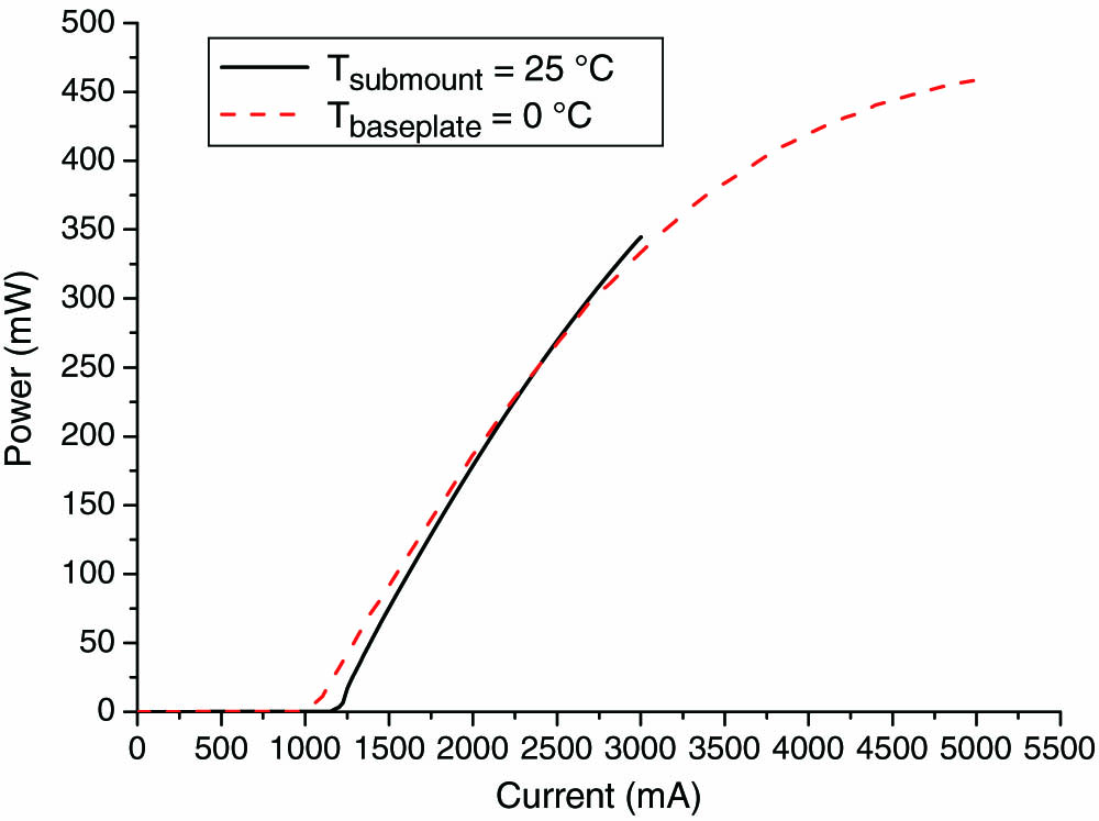
Figure 1.Output power as a function of bias current.
Because of a large chirp, no pulses are observed at the output of the laser. We previously demonstrated that this chirp is nearly linear [9]. It can be compensated with an appropriate length of standard single-mode fiber providing the required group delay dispersion to compress the pulses [11]. This single-section solution for mode locking has been compared with the two-section method (gain section and saturable absorber) in [12]. The optical spectrum is plotted on Fig. 2. The square shape of the spectrum with sheer sides and a plateau is typical of a MLL. The of the envelope of the spectrum is 5.8 nm, compatible with beat-note generation up to 0.72 THz.

Figure 2.Optical spectrum at 2 A.
All electrical measurements have been done with an FSU 67 Rohde & Schwarz electrical spectrum analyzer and a 75 GHz bandwidth XPDV3120R photodiode (PD) form . The RF spectrum up to 70 GHz is plotted on Fig. 3 for a photocurrent of 1.6 mA. We can see the fundamental tone at 4.4 GHz and all the harmonics up to the 14th harmonic (65.6 GHz). This upper limitation is due to our setup. For a cleaved FP laser, the fundamental RF tone linewidth goes down to 300 Hz, which is, to our knowledge, the best-reported value for an InAs/InP QD MLL. The gain obtained by the optical compression on the fundamental RF tone is about 30 dB (Fig. 4), the optimized fiber length being 2.5 km.
Figure 3.RF spectrum with optical compression at 2.24 A ().
Figure 4.Fundamental tone with and without optical compression.
We have then measured the pulse train of our chip with a sampling scope (Fig. 5). The extinction ratio is about 10 dB, the precision of this measurement being limited since the oscilloscope is triggered by the signal itself, leading to a significant time jitter.
Figure 5.Sampling scope trace of detected pulse train for passive mode-locking.
We finally characterized the pulses with a second-harmonic generation (SHG) autocorrelator. The autocorrelation trace with optical compression is plotted in Fig. 6, its FWHM autocorrelation trace being 1.6 ps, corresponding to a pulse duration of 1.1 ps assuming a Gaussian shape. The time bandwidth product is about 0.8, which means the pulses are not transform limited, i.e., after optical compression, the signal still contains some residual phase distortion. Assuming a reasonable fiber-coupled power of 100 mW, a 4.3 GHz repetition rate and a 1.1 ps pulse duration, the corresponding peak power is 21 W.
Figure 6.Autocorrelation trace with optical compression at 2.14 A.
3. MONOLITHICALLY INTEGRATED MILLIMETER-WAVE TRANSCEIVER BASED ON OPTICAL HETERODYNE GENERATION
Millimeter-wave semiconductor laser sources are of growing interest in the development of wireless communication systems [13], particularly in the context of carrier-frequency increase. Integrated devices able to generate carrier frequencies from 30 to 200 GHz have already been demonstrated [13–16]. Monolithic integration promises to allow cost-effective production, tighter packaging, and fewer alignment issues [17,18]. In this part, we present a monolithic integrated millimeter source that integrates two tunable distributed feedback (DFB) lasers with an electro-optical modulator and a high-speed uni-traveling carrier (UTC) PD on the same substrate. The principle of the source and its millimeter-wave transmission application is schematized in Fig. 7.
Figure 7.General principle.
The two optical tones are combined, modulated, and converted into a millimeter-wave signal on a high-speed PD. If we call and the two wavelengths from the two DFB lasers, the carrier frequency is defined by After being data modulated, the optical signal is converted into an electrical millimeter-wave range signal, transmitted in free space thanks to two antennas, received, and at last demodulated to retrieve data.
The photonic integrated circuit is represented in Fig. 8. The two DFB lasers are 1 mm long, and their outputs are combined thanks to a multimode-interference (MMI) coupler. Semiconductor optical amplifiers are also inserted in the circuit in order to compensate for losses and to properly balance the level of the two optical tones. On one side of the device, two UTC PDs are placed in order to perform opto-electronic conversion. On the other side of the chip, an optical access to the chip can be used to monitor the optical signal. The whole device is 4.4 mm long and 0.7 mm wide.
Figure 8.View of the monolithic chip for millimeter-wave transmission.
We used the setup presented in Fig. 9 to evaluate the tuning range and the opto-electronic response of the device. A multi-DC probe is used to apply the bias currents to the different sections. A coplanar probe provides access to the photocurrent of one of the PDs and allows its proper biasing at with a bias tee. Another coplanar probe is used to drive the electro-optical modulator section. On the other side of the chip, a lensed fiber is used to couple the optical signal from the back of the chip.
Figure 9.General view of the test setup.
By biasing the two lasers independently, we demonstrated a continuous thermal tuning of their frequency difference from 5 to 110 GHz. The measured optical spectra are presented in Fig. 10 next to the corresponding electrical spectra of the beat note from the PD. As the two laser frequencies are close to each other, the wavelength of DFB2 changes also due to thermal cross talk. The additional optical tone appearing for the upper curves on graph (5–40 GHz) is due to the tendency of the DFB lasers to exhibit a dual-mode behavior for large bias currents, probably because of some residual reflections that can occur, for example, on the butt joints, in the MMI coupler, or on the back of the PDs. For measurements above 65 GHz, an external mixer is used on the electrical spectrum analyzer in combination with the same coplanar probe and bias tee.
Figure 10.Electrical and optical spectra obtained for different laser biasing conditions.
From this monolithic chip, a short-distance (up to 50 cm) wireless transmission experiment was assembled. Figure 11 shows the elements of the setup.
Figure 11.Wireless data transmission experiment diagram.
The beat-note frequency was fixed at 100 GHz by choosing the appropriate bias point for the different sections of the chip. The signal from a generator [pseudorandom binary sequence (PRBS)] is sent to the modulation section of the chip through a bias tee, the modulator being reverse biased at . In these conditions, the photocurrent from the biased PD is 2.18 mA. After it is photo-detected in the chip, the modulated millimeter signal is sent to a first horn antenna, then retrieved by a second horn antenna, downconverted using a harmonic mixer, amplified, and finally rectified using a crystal diode detector, filtered, and sent to a sampling oscilloscope. With this setup, we were able to demonstrate a clear open eye compatible with a good data transmission up to . The eye diagram is presented in Fig. 12. Further characterizations are ongoing to quantify the extinction ratio, and transmissions at higher data rates and for longer distances are currently under test.
Figure 12.Eye diagram for transmission.
4. PRECISE CONTROL AND STABILIZATION OF BROADBAND ARBITRARY FREQUENCY SWEEPS BY FIBERED SELF-HETERODYNE TECHNIQUES
Lasers exhibiting high spectral purity and stability, together with fast, broadband, and precise tunability, are a key requirement for many applications, such as coherent light ranging and 3D imaging using the frequency modulated continuous wave (FMCW) technique [19–21], optical processing of radiofrequency signals [22–24], and coherent manipulation of atoms for quantum information storage [25,26].
A self-referenced laser frequency stabilization scheme, compatible with high-speed frequency agility, has been proposed and demonstrated by several research groups for the generation of highly linear chirps [27–34]. This scheme is based on phase-locked loop stabilization of the laser through a self-heterodyne beat signal obtained from an unbalanced fiber interferometer. An example of implementation is illustrated in Fig. 13. The output of the tunable laser is split using an acousto-optic modulator (AO). The first-order beam travels through a fiber delay line and is shifted in frequency by . The zeroth-order beam is not delayed and is split into two unequal portions by a fiber splitter: 10% is used for the control of the sweep and 90% corresponds to the output of the laser, used for out-of-loop measurement or for the dedicated application. The zeroth-order and the delayed and shifted first-order beams are recombined interferometrically using a fiber combiner and detected by a PD. The output of the PD is mixed down using a reference signal. The resulting low-frequency error signal is then amplified, filtered with a proportional-integral (PI) filter that ensures loop stability, and then directed to the laser frequency tuning input. A time-varying control voltage is added to the laser input in order to set the nominal optical frequency sweep.
Figure 13.Setup for precise control and stabilization of broadband arbitrary frequency sweeps by fibered self-heterodyne technique. Abbreviations are defined in the text.
Let us express the optical field before the optical frequency discriminator as with the nominal optical frequency of the laser without sweep, the nominal frequency sweep obtained through the time-varying control signal, and the optical phase that includes the frequency noise and the errors from the nominal sweep.
represents the error signal and can be then expressed as if the reference signal verifies where amplitudes and , depending on the parameters of the experiment, have no incidence on the main result. If the frequency sweep is a linear chirp, , the frequency of the reference signal is then constant and equal to [27–34]. Satyan et al. have demonstrated that this technique can be adapted for an arbitrary frequency sweep of a DFB laser at 1.5 μm, by using a voltage-controlled oscillator (VCO) to generate the reference signal, and by using Eqs. (4) and (5) to derive the reference signal from the desired shape of the frequency sweep [33]. They achieved an exponential decrease of the slope of the optical frequency from to over 1 ms. However, in their setup, the agility of the laser will be ultimately limited by the agility of the VCO and may not be sufficient for applications requiring arbitrary sweeps with rapid and abrupt variations of the optical frequency.
We report here the development of a tunable laser whose arbitrary frequency sweep can be precisely controlled, with abrupt variations of the slope of the optical frequency. In our demonstration, the nominal sweep is arbitrarily defined by an arbitrary waveform generator (AWG, Lecroy Arbstudio), which provides both the control and the reference signals together with the RF signal driving the AO to ensure a constant phase relationship between them. We developed this laser source to engrave holographic Bragg gratings and to burn spectral holes in crystal for optical processing of radiofrequency signals [22,35]. Consequently, the wavelength of the laser has to match a specific absorption line of , which is close to 793.4 nm. The laser is a DFB semiconductor laser (“DL-DFB” model from Toptica), and the control and corrected error signal is applied to a DC-coupled current modulation input (named “FET-input” on this model). The optical fiber delay has been fixed to 9.8 ns to limit the bandwidth of the reference signal to a value compatible with the AWG.
Since the laser exhibits a highly nonlinear response to the control signal, we used an open-loop predistortion technique to remove the systematic chirp nonlinearities as much as possible [32,33]. The setup is illustrated in Fig. 14(a) and includes an out-of-loop optical frequency discriminator, similar to the one described above. The PD signal is acquired by an oscilloscope and digitally processed in order to deduce the measured optical frequency and then correct the control voltage applied to the laser. The nominal frequency sweep is shown in Fig. 14(b): the optical frequency is swept over 20 GHz within 250 μs, with a local slope varying from to within 15 μs. After tens of iterations, we obtained the predistorted control voltage, shown in Fig. 14(c). The measured error from the nominal sweep when this predistorted voltage is applied is presented in blue in Figs. 14(d) and 14(e). When the optical frequency sweep is locked to a reference electronic signal thanks to the opto-electronic feedback loop previously described in Fig. 13, the error is reduced down to less than 1 MHz. Consequently, we achieved precisely controlled arbitrary frequency sweeps over 20 GHz within 250 μs with a local slope varying from to in 15 μs. These performances obtained with a DFB laser at 793.4 nm are compatible with the requirements for optical processing of radiofrequency signals [35].
Figure 14.(a) Setup for the predistortion correction, using an out-of-loop optical frequency discriminator. (b) Nominal frequency sweep. (c) Predistorted control voltage. (d), (e) Error from the nominal frequency sweep: in blue for the free-running laser (with the predistorted control voltage) and in green for the optoelectronic feedback loop in which the optical frequency sweep is phase locked to a reference electronic signal.
5. DOUBLY TUNABLE DUAL-FREQUENCY SOLID-STATE LASER
Among the techniques for the generation of optically carried microwave to THz signals, the optical heterodyning of two laser sources has proven its capabilities. Indeed, the attainable tuning range and speed are far above the ones that are offered by the external modulation of continuous lasers [1]. Because of its high integration level, the preferred scheme relies on the mixing of two semiconductor laser sources ([36] and Section 3 of this paper). However, their intrinsic linewidth, usually above a few hundreds of kHz, severely constrains the design of the phase-locked loops that are necessary to reach the low phase noise levels required by radar or electronic warfare applications [37]. A promising alternative is the solid-state dual-frequency laser (DFL), which combines in a compact setup the low-noise properties of solid-state lasers and the capabilities of optical heterodyning [38,39]. Moreover, due to the use of a single cavity to produce the two laser beams, their frequency difference is less sensitive to environmental perturbations and usually exhibits a sub-kHz linewidth [40]. We recently demonstrated the realization of a low-noise, widely tunable optoelectronic oscillator based on the stabilization of a solid-state DFL on a 100 m long fiber delay line [41]. To reduce the size of the setup, a high- fiber-ring resonator (FRR) would ideally replace the delay line [42]. It requires independent control of the two optical frequencies of the laser, since it is necessary to lock them on two different resonances of the FRR. In previous realizations of solid-state DFLs, the intracavity electro-optic element allows only the control of the frequency difference. In the following, we describe the realization and characterization of a doubly tunable solid-state DFL source.
The laser scheme is given in Fig. 15. The gain medium is a 1 mm long erbium-ytterbium co-doped phosphate glass disk, HR/AR coated at 1.5 μm, pressed onto a sapphire window. The 15 mm long cavity is closed by a 20 mm radius of curvature concave output coupler (1% transmission at 1.5 μm). Two AR-coated lead lanthanum zirconate tantalate (PLZT) electro-optic plates (500 μm thickness), oriented at 90° from each other, are inserted in the cavity. Finally, a z-cut YVO4 plate (100 μm thickness) acts as an etalon within the cavity. Due to its birefringence when it is slightly angled relative to normal incidence, it ensures stable dual-frequency operation with a frequency separation of 10 GHz, the cavity free spectral range (see [43] and [44] for further details on the birefringent etalon principle).
Figure 15.Solid-state DFL source cavity principle. V1 and V2 are the voltages that allow the independent control of the two frequencies.
When pumped by two polarization-combined single-mode laser diodes at 975 nm delivering 1 W, the laser outputs 20 mW of optical power, 8 mW being coupled within a single-mode fiber. We first measured the phase noise of the beat note at 10 GHz (after polarization projection of the two modes), together with the optical phase noise of one of the optical modes. The results are shown in Fig. 16.
Figure 16.Phase noise of one of the optical modes (red curve) and phase noise of the beat note at 10 GHz (blue curve).
As expected, the laser delivers a high spectral purity beat note (a few hundreds of Hz linewidth), with a phase noise level much lower than the one of the individual optical lines for frequency offsets below 100 kHz. It highlights the advantage of the single-cavity scheme to cancel out environmental fluctuations. We also checked the tunability of the beat note and obtained a 1 GHz tunability around 10 GHz by applying up to 400 V on any of the two electro-optic elements.
To verify the ability of this laser to be used in a resonator-based optoelectronic oscillator, we implemented the stabilization of one of the optical frequencies to a high- FRR. This one is made of two standard 10 dB fiber couplers and 20 m standard fiber at 1.5 μm and exhibits a quality factor of . The locking scheme is described in Fig. 17 and is based on a standard Pound–Drever–Hall (PDH) scheme, in which the frequency modulation and the feedback signal are summed and directly applied to the electro-optic element corresponding to the optical mode to be controlled.
Figure 17.Locking scheme of one of the DFL optical lines on a high- FRR. PDH: Pound–Drever–Hall setup. PID: proportional-integral-derivative controller.
The optical phase noises are given in Fig. 18, in the free-running and frequency-locked cases. As expected, a large reduction of the optical phase noise is obtained. At the same time, an increase of the beat-note phase noise is observed (blue curve) that can be explained by the fact that the two optical modes are no more correlated when one of them is locked on a frequency reference independent from the laser cavity. It should be noted that a large part of this phase-noise degradation could be cancelled by applying to the second electro-optic element a properly balanced fraction of the feedback voltage delivered within the PDH to the first one.
Figure 18.Phase noise of one of the optical modes: free running (red curve) and locked (orange curve). Phase noise of the beat note when locked (blue curve).
This laser source should allow us in the near future to implement a compact, low-phase, noise-tunable optoelectronic oscillator by combining the PDH scheme with a stabilization scheme similar to the one described in [41].
6. CONCLUSION
In this paper, we presented the realization of several laser sources dedicated to the implementation of advanced microwave photonic functions, such as optically assisted analog-to-digital conversion (MLL), wireless millimeter-wave transmission (monolithic photonic transceiver), microwave signal processing (arbitrary tunable laser), and low-noise and tunable signal generation (solid-state DFL).
References
[1] J. Yao. Microwave photonics. J. Lightwave Technol., 27, 314-335(2009).
[2] D. Marpaung, C. Roeloffzen, R. Heidemann, A. Leinse, S. Sales, J. Capmany. Integrated microwave photonics. Laser Photon. Rev., 7, 506-538(2013).
[3] R. Holzwarth, M. Zimmermann, T. Udem, T. W. Hansch. Clockworks and the measurement of laser frequencies with a mode-locked frequency comb. IEEE J. Quantum Electron., 29, 739-741(1993).
[4] G. Valley. Photonic analog-to-digital converters. Opt. Express, 15, 1955-1982(2007).
[5] A. A. Ballman, A. M. Glass, R. E. Nahory, H. Brown. Double doped low etch pit density InP with reduced optical absorption. J. Cryst. Growth, 62, 198-202(1983).
[6] P. B. Hansen, G. Raybon, U. Koren, B. I. Miller, M. G. Young, M. A. Newkirk, M.-D. Chien, B. Tell, C. A. Burrus. 2 cm long monolithic multisection laser for active modelocking at 2.2 GHz. Electron. Lett., 29, 739-741(1993).
[7] P. W. Juodawlkis, J. J. Plant, W. Loh, L. J. Missaggia, F. J. O’Donnell, D. C. Oakley, A. Napoleone, J. Klamkin, J. T. Gopinath, D. J. Ripin, S. Gee, P. J. Delfyett, J. P. Donnelly. High-power, low-noise 1.5-μm slab-coupled optical waveguide (SCOW) emitters: physics, devices and applications. IEEE J. Sel. Top. Quantum Electron., 17, 1698-1714(2011).
[8] F. Lelarge, B. Dagens, J. Renaudier, R. Brenot, A. Accard, F. van Dijk, D. Make, O. Le Gouezigou, J. G. Provost, F. Poingt, J. Landreau, O. Drisse, E. Derouin, B. Rousseau, F. Pommereau, G. H. Duan. Recent advances on InAs/InP quantum dash based semiconductor lasers and optical amplifiers operating at 1.55 μm. IEEE J. Sel. Top. Quantum Electron., 13, 111-124(2007).
[9] M. Faugeron, F. Lelarge, M. Tran, Y. Robert, E. Vinet, A. Enard, J. Jacquet, F. van Dijk. High peak power, narrow RF linewidth asymmetrical cladding quantum-dash mode-locked lasers. IEEE J. Sel. Top. Quantum Electron., 19, 1101008(2013).
[10] F. van Dijk, M. Faugeron, F. Lelarge, M. Tran, M. Chtioui, Y. Robert, E. Vinet, A. Enard, J. Jacquet. Asymmetrical cladding quantum dash mode-locked laser for terahertz wide frequency comb. Proceedings of Microwave Photonics, 282-285(2013).
[11] K. Sato. Optical pulse generation using Fabry–Perot lasers under continuous-wave operation. IEEE J. Sel. Top. Quantum Electron., 9, 1288-1293(2003).
[12] R. Rosales, K. Merghem, A. Martinez, A. Akrout, J.-P. Tourrenc, A. Accard, F. Lelarge, A. Ramdane. InAs/InP quantum-dot passively mode-locked lasers for 1.55-μm applications. IEEE J. Sel. Top. Quantum Electron., 17, 1292-1301(2011).
[13] A. Stöhr. Photonic millimeter-wave generation and its applications in high data rate wireless access. Proceedings of Microwave Photonics, 7-10(2010).
[14] E. Rouvalis, M. Cthioui, F. van Dijk, M. J. Fice, G. Carpintero, C. C. Renaud, A. J. Seeds. 170 GHz Photodiodes for InP-based photonic integrated circuits. IEEE Photonics Conference, 88-89(2012).
[15] S. Ristic, A. Bhardwaj, M. J. Rodwell, L. A. Coldren, L. A. Johansson. An optical phase-locked loop photonic integrated circuit. J. Lightwave Technol., 28, 526-538(2010).
[16] F. Van Dijk, A. Accard, A. Enard, O. Drisse, D. Make, F. Lelarge. Monolithic dual wavelength DFB lasers for narrow linewidth heterodyne beat-note generation. Proceedings of Microwave Photonics, 73-76(2011).
[17] M. Hamacher, D. Trommer, K. Li, H. Schroeter-Janssen, W. Rehbein, H. Heidrich. Fabrication of a heterodyne receiver OEIC with optimized integration process using three MOVPE growth steps only. IEEE Photon. Technol. Lett., 8, 75-77(1996).
[18] M. Lu, H. C. Park, A. Sivananthan, J. S. Parker, E. Bloch, L. A. Johansson, M. J. W. Rodwell, L. A. Coldren. Monolithic integration of a high-speed widely tunable optical coherent receiver. IEEE Photon. Technol. Lett., 25, 1077-1080(2013).
[19] K. Iiyama, W. Lu-Tang, K. Hayashi. Linearizing optical frequency-sweep of a laser diode for FMCW reflectometry. J. Lightwave Technol., 14, 173-178(1996).
[20] M.-C. Amann, T. Bosch, M. Lescure, R. Myllyla, M. Rioux. Laser ranging: a critical review of usual techniques for distance measurement. Opt. Eng., 40, 10-19(2001).
[21] Z. Barber, W. Babbitt, B. Kaylor, R. Reibel, P. Roos. Accuracy of active chirp linearization for broadband frequency modulated continuous wave ladar. Appl. Opt., 49, 213-219(2010).
[22] V. Lavielle, I. Lorgeré, J. Le Gouët, S. Tonda, D. Dolfi. Wideband versatile radio-frequency spectrum analyzer. Opt. Lett., 28, 384-386(2003).
[23] C. Renner, R. Reibel, M. Tian, T. Chang, W. R. Babbitt. Broadband photonic arbitrary waveform generation based on spatial-spectral holographic materials. J. Opt. Soc. Am. B, 24, 2979-2987(2007).
[24] H. Linget, L. Morvan, J. Le Gouët, A. Louchet-Chauvet. Time reversal of optically carried radiofrequency signals in the microsecond range. Opt. Lett., 38, 643-645(2013).
[25] O. Guillot-Noël, Ph. Goldner, E. Antic-Fidancev, A. Louchet, J.-L. Le Gouët, F. Bretenaker, I. Lorgeré. Quantum storage in rare-earth doped crystals for secure networks. J. Lumin., 122–123, 526-528(2007).
[26] M. Tian, T. Chang, K. D. Merkel, W. Randall, W. R. Babbitt. Reconfiguration of spectral absorption features using a frequency-chirped laser pulse. Appl. Opt., 50, 6548-6554(2011).
[27] Y. T. Chen. Use of single-mode optical fiber in the stabilization of laser frequency. Appl. Opt., 28, 2017-2021(1989).
[28] C. Greiner, B. Boggs, T. Wang, T. W. Mossberg. Laser frequency stabilization by means of optical self-heterodyne beat-frequency control. Opt. Lett., 23, 1280-1282(1998).
[29] G. A. Cranch. Frequency noise reduction in erbium-doped fiber distributed-feedback lasers by electronic feedback. Opt. Lett., 27, 1114-1116(2002).
[30] V. Crozatier, G. Gorju, F. Bretenaker, J.-L. Le Gouet, I. Lorgere, C. Gagnol, E. Ducloux. Phase locking of a frequency agile laser. Appl. Phys. Lett., 89, 261115(2006).
[31] G. Gorju, A. Jucha, A. Jain, V. Crozatier, I. Lorgeré, J.-L. Le Gouët, F. Bretenaker, M. Colice. Active stabilization of a rapidly chirped laser by an optoelectronic digital servo-loop control. Opt. Lett., 32, 484-486(2007).
[32] P. Roos, R. Reibel, T. Berg, B. Kaylor, Z. Barber, W. Babbitt. Ultrabroadband optical chirp linearization for precision metrology applications. Opt. Lett., 34, 3692-3694(2009).
[33] N. Satyan, A. Vasilyev, G. Rakuljic, V. Leyva, A. Yariv. Precise control of broadband frequency chirps using optoelectronic feedback. Opt. Express, 17, 15991-15999(2009).
[34] H. Jiang, F. Kéfélian, P. Lemonde, A. Clairon, G. Santarelli. An agile laser with ultra-low frequency noise and high sweep linearity. Opt. Express, 18, 3284-3297(2010).
[35] I. Lorgere, G. Gorju, L. Menager, V. Lavielle, F. Bretenaker, J.-L. Le Gouet, S. Molin, L. Morvan, S. Tonda-Goldstein, D. Dolfi, J.-P. Huignard. Broadband RF spectrum analyzer based on spectral hole burning microwave photonics. Proceedings of Microwave Photonics, 1-4(2009).
[36] L. Ponnampalam, M. J. Fice, F. Pozzi, C. Renaud, D. C. Rogers, I. F. Lealman, D. G. Moodie, P. J. Cannard, C. Lynch, L. Johnston, M. J. Robertson, R. Cronin, L. Pavlovic, L. Naglic, M. Vidmar, A. J. Seeds. Monolithically integrated photonic heterodyne system. J. Lightwave Technol., 29, 2229-2234(2011).
[37] K. Balakier, M. J. Fice, L. Ponnampalam, C. Renaud, A. J. Seeds. Tunable monolithically integrated photonic THz heterodyne system. Proceedings of International Topical Meeting on Microwave Photonics, 286-289(2012).
[38] M. Brunel, F. Bretenaker, A. Le Floch. Tunable optical microwave source using spatially resolved laser eigenstates. Opt. Lett., 22, 384-386(1997).
[39] G. W. Baxter, J. M. Dawes, P. Dekker, S. Knowles. Dual polarization frequency-modulated laser source. IEEE Photon. Technol. Lett., 8, 1015-1017(1996).
[40] G. Pillet, L. Morvan, M. Brunel, F. Bretenaker, D. Dolfi, M. Vallet, J.-P. Huignard, A. Le Floch. Dual-frequency laser at 1.5 μm for optical distribution and generation of high-purity microwave signals. J. Lightwave Technol., 26, 2764-2773(2008).
[41] J. Maxin, G. Pillet, B. Steinhausser, L. Morvan, O. Llopis, D. Dolfi. Widely tunable opto-electronic oscillator based on a dual-frequency laser. J. Lightwave Technol., 31, 2919-2925(2013).
[42] K. Saleh, P. H. Merrer, O. Llopis, G. Cibiel. Optoelectronic oscillator based on fiber ring resonator: overall system optimization and phase noise reduction. Proceedings of the IEEE International Frequency Control Symposium, 1-6(2012).
[43] J. Le Gouët, L. Morvan, M. Alouini, J. Bourderionnet, D. Dolfi, J. Huignard. Dual-frequency single-axis laser using a lead lanthanum zirconate tantalate (PLZT) birefringent etalon for millimeter wave generation: beyond the standard limit of tunability. Opt. Lett., 32, 1090-1092(2007).
[44] G. Pillet, L. Morvan, L. Manager, A. Garcia, S. Babiel, A. Stöhr. 100 GHz phase-locked dual-frequency laser. Proceedings of IEEE Topical Meeting on Microwave Photonics, 1-4(2012).

