• Chinese Optics Letters
  • Vol. 17, Issue 3, 030604 (2019)
E. W. Lam* and T. D. C. Little**
Author Affiliations
  • Electrical and Computer Engineering Department, Boston University, Boston, Massachusetts 02215, USA
  • show less
    DOI: 10.3788/COL201917.030604 Cite this Article Set citation alerts
    E. W. Lam, T. D. C. Little. Visible light positioning: moving from 2D planes to 3D spaces [Invited][J]. Chinese Optics Letters, 2019, 17(3): 030604 Copy Citation Text show less
    Positioning 3D coordinates for devices in an indoor space using visible light.
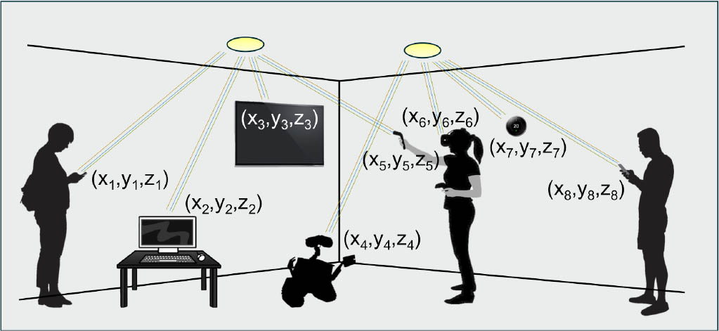
    Fig. 1. Positioning 3D coordinates for devices in an indoor space using visible light.
    Typical room layout for a VLP system. The geometric angles between the receiver and transmitter are also noted.
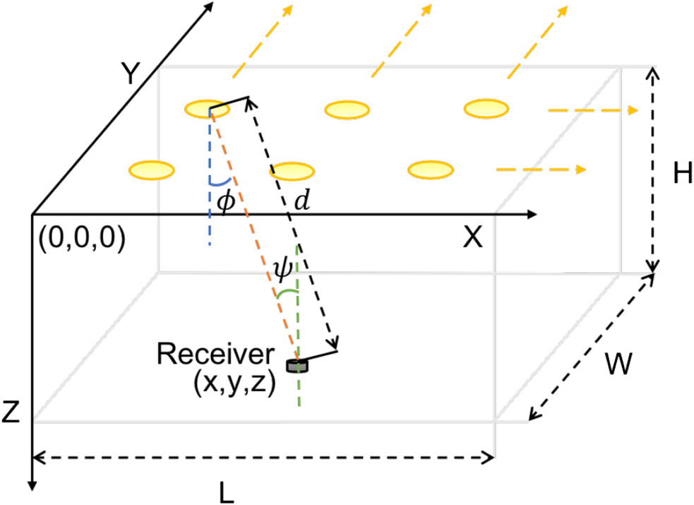
    Fig. 2. Typical room layout for a VLP system. The geometric angles between the receiver and transmitter are also noted.
    Taxonomy of positioning algorithms showing the main physical modalities, mathematical techniques, and extra peripherals.
    Fig. 3. Taxonomy of positioning algorithms showing the main physical modalities, mathematical techniques, and extra peripherals.
    Example multiplexing schemes to prevent luminaire signal interference: a, TDM, b, FDM, c, SM, and d, WDM.
    Fig. 4. Example multiplexing schemes to prevent luminaire signal interference: a, TDM, b, FDM, c, SM, and d, WDM.
    Common benchmarks shown on a CDF: a, best accuracy, b, accuracy for 95% of cases, and c, accuracy for 100% of cases.
    Fig. 5. Common benchmarks shown on a CDF: a, best accuracy, b, accuracy for 95% of cases, and c, accuracy for 100% of cases.
    Changing planes affects positioning accuracy as seen in these CDF curves.
    Fig. 6. Changing planes affects positioning accuracy as seen in these CDF curves.
    Receivers at positions a and b have the same FOV. However, the receiver at position b sees one less transmitter than the receiver at position a.
    Fig. 7. Receivers at positions a and b have the same FOV. However, the receiver at position b sees one less transmitter than the receiver at position a.
    In a typical 6 m×6 m space with four luminaires placed at positions 2 m away from each other, depending on the plane, a, 1 m away and b, 2 m away, the number of transmitters seen across the space changes.
    Fig. 8. In a typical 6m×6m space with four luminaires placed at positions 2 m away from each other, depending on the plane, a, 1 m away and b, 2 m away, the number of transmitters seen across the space changes.
    Signal strength fading with height. While the signal strength directly under the luminaire increases, the region of poor signal strength increases.
    Fig. 9. Signal strength fading with height. While the signal strength directly under the luminaire increases, the region of poor signal strength increases.
    Concept of ray–surface positioning showing angles of the steerable laser and Lambertian profile.
    Fig. 10. Concept of ray–surface positioning showing angles of the steerable laser and Lambertian profile.
    MSE comparing ray–surface positioning to multilateration. Ray–surface provides 3D positioning and is significantly better than multilateration.
    Fig. 11. MSE comparing ray–surface positioning to multilateration. Ray–surface provides 3D positioning and is significantly better than multilateration.
    ReferencePhysicalMathematicalSources/SinksPeripheralsReported Volume or PlaneAccuracy (cm)3D
    [17]RSSMultilateration4 TXs/1 PD Pl: [6m×6m]@3m5.9No
    [25]RSSTrilateration16 TXs/1 PDIMUPl: [20m×20m]@3m40No
    [27]RSSFingerprinting4 TXs/1 PD6 bluetooth APsPl: [5m×5m]@3m6No
    [22]RSSFingerprinting4 TXs/1 PDCameraPl: [5m×5m]@3m10No
    [18]PDOATrilateration3 TXs/1 PDTime Sync.Pl: [1m×1.2m]@3m1.8No
    [32]TDOAMultilateration1 TX/5 PDsTime Sync.Pl: [5m×5m]@3m0.01No
    [15]TOA/PDOAMultilateration5 TXs/1 PDTime Sync.Pl: [5m×5m]@3m0.01Yes
    [19]AOATriangulation5 TXs/Camera Pl: [0.71m×0.73m]@2.46m10Yes
    [33]AOA/ADOATriangulation4 TXs/Camera Pl: [8m×8m]@3m3.2Yes
    [26]AOATriangulation3 TXs/1 PDAccelerometerPl: [5m×3m]@3m25Yes
    [30]AOATriangulation4 TXs/8 PDs8 aperturesPl: [5m×5m]@2m10Yes
    [28]AOA/RSSDifferential1 TX/3 PDsTilted RXsVo: [2m×2m×2.5m]6Yes
    [34]AOA/RSSDifferential1 TX/1 TXRotating RXPl: [6m×6m×11.25m]4Yes
    [11]AOA/RSSRay–surface1 TX/1 PDSteerable laserPl: [6m×6m]@3m13Yes
    [24]RSSImaging4 TXs/Camera Pl: [1.2m×1.2m]@1.2m6Yes
    Table 1. Representative Sampling of State-of-the-art in Visible Light Positioning
    E. W. Lam, T. D. C. Little. Visible light positioning: moving from 2D planes to 3D spaces [Invited][J]. Chinese Optics Letters, 2019, 17(3): 030604
    Download Citation