
Ting YU, Zhuo CHEN, Tiancheng LI, Degui SUN. Precision Measurement and Theoretical Analysis of SOI Waveguide Transmission Loss and Butt-coupling Loss[J]. Acta Photonica Sinica, 2021, 50(7): 268
- Acta Photonica Sinica
- Vol. 50, Issue 7, 268 (2021)
Abstract
0 Introduction
Silicon-On-Insulator (SOI) based photonics has spurred a great interest in the optical interconnection in modern computers, optical communications and microelectronic systems[
Over the past decade, silicon photonics has attracted dense science research and product development around the world, and a number of optical SOI waveguide components have been demonstrated in the laboratory, including compact and low-loss SOI passive waveguide devices, high-speed silicon modulators, high-speed GeSi detectors, silicon Raman lasers, and thermal optical devices[
In the traditional cut-back method, the measuring accuracy is limited, so in this work the method of optical waveguide channel with two end-faces, Fabry-Perot cavity measuring method is exploited in order to make the optical waveguide transmission loss and the fiber-chip coupling loss. As a result, the high measurement precisions of both the optical transmission loss and the fiber-chip butting coupling loss of SOI waveguide are reached. Finally, the measurement accuracies of these two optical losses are theoretically modelled.
1 SOI waveguide structure and scanning electron microscopy tests
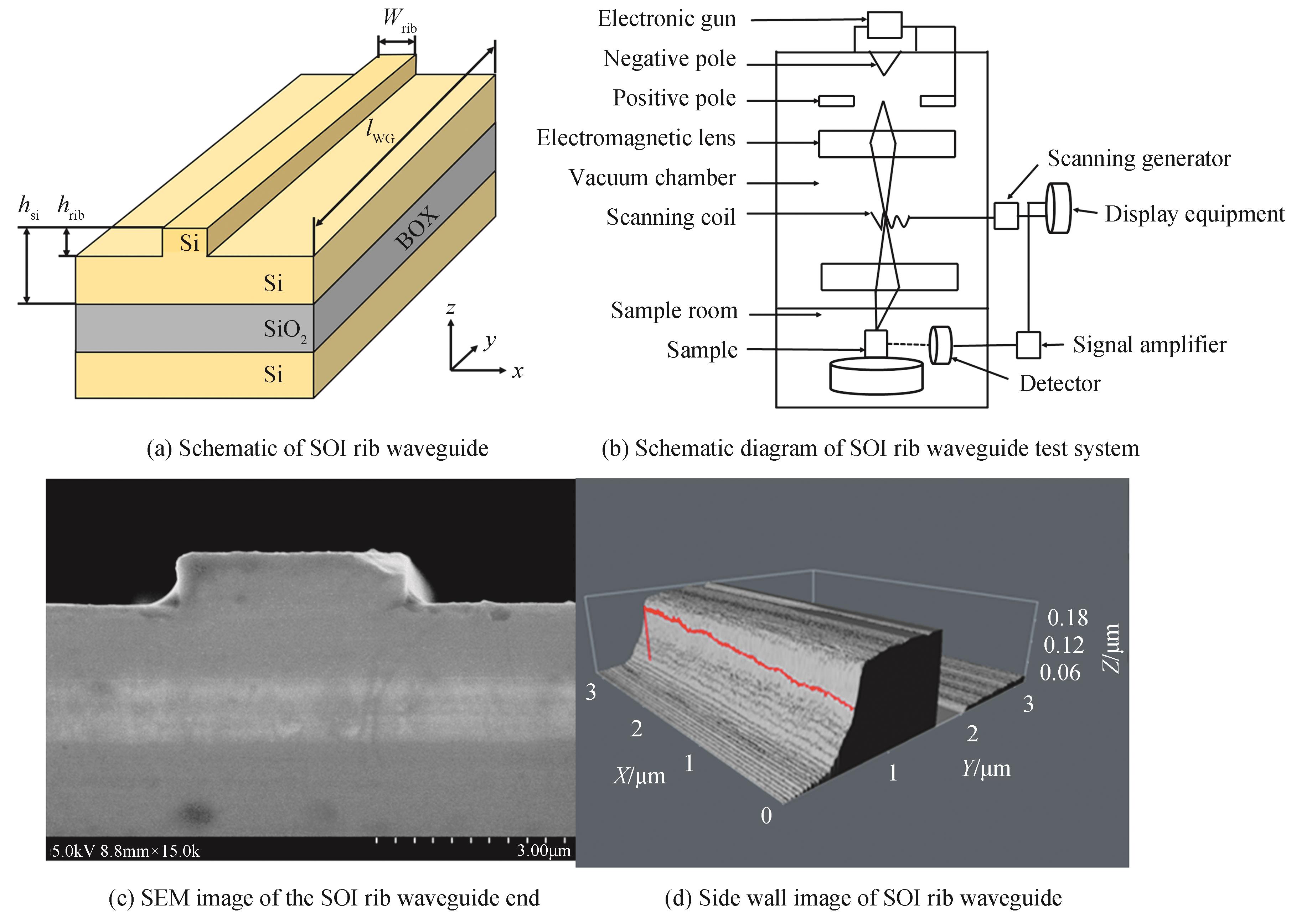
As an SOI platform, the BOX thickness was 2.0 μm and the silicon film thickness is hsi=1.5 μm. Then, the rib waveguides were fabricated as follows: the rib width and height are Wrib=4 μm and hrib=0.5 um, respectively. The schematic of an SOI rib waveguide structure is shown in Fig. 1(a). A scanning electron microscope (SEM, Hitachi S-4800) is used to measure the polished-end quality of the waveguide and a schematic configuration of the SEM system is shown in Fig. 1(b), so an image of the end-face of SOI waveguide taken by the SEM system is shown in Fig. 1 (c), and a side-view image taken by a Confocal Laser Scanning Microscope (CLSM) is shown in Fig. 1(d). It can be clearly seen that the SOI waveguide etching angle is about 90°. The refractive index of BOX layer is 1.444, and the refractive index of silicon film is 3.45, an upper cladding layer having the refractive index of 1.444 is also deposited on the top of the rib waveguides, which is not drawn in Fig. 1(a). For TE mode, the effective refractive index is 3.414 6.
![]()
Figure 1.SOI rib waveguide structure and test image
2 Measurements for optical transmission loss/fiber-chip butt-coupling loss of SOI waveguides
Measurements for the optical transmission loss of SOI waveguides were performed using a 1 550 nm light source and a single-mode SMF-28 fiber produced by Corning and further the fiber-chip butt-coupling loss of the waveguide was reached. At the coupling condition of SOI waveguide and optical fiber end-faces, the Fabry-Perot resonant cavity (also known as F-P cavity) was formed to respond to continuous phase modulation by light wave output, and the waveguide optical transmission loss was measured directly[
In the measurement experiment, a Positive Temperature Coefficient (PTC) heating sheet was used to heat the bottom of SOI waveguide, the effect of uniform change of SOI waveguide refractive index is achieved. PTC heating plate can effectively control the waveguide heating temperature, obtain the relationship between output power and heating temperature on the optical power detector, and then record the response of output power to temperature change. The optical transmission loss of SOI waveguide can be calculated by obtaining the extreme values of resonant output power amplitude, namely, the maximum and minimum values of the resonant output, which is given by
where lWG represents the length of the waveguide channel, R represents the Fresnel reflection coefficient on both end faces of the waveguide[
By testing the straight waveguide on the SOI chip, the response curve of the output power of an optical resonator varying with temperature was obtained. In the temperature range of 20 °C~45 °C, a semi-periodic response curve of the output power of optical resonator was obtained as shown in Fig. 2. In Fig. 2(a), the data of three waveguide channels with a length of 8.37 mm that were measured with the hand-set values of temperature. For transmission powers shown in Fig. 2(a), Tmin values in the low and high temperature periods are set as Tmin (L) and Tmin (H), respectively, then among the three waveguides, these values are: for WG1, Tmin(L)=0.270 μW, Tmax=6.053 μW and Tmin(H)=0.298 μW; for WG2, Tmin(L)=0.545 μW, Tmax=5.902 μW and Tmin(H)=0.5343 μW; for WG3, Tmin(L)=0.197 μW, Tmax=4.325 μW, Tmin(H)=0.321 μW.
![]()
Figure 2.Propagation losses test of three SOI waveguides and the responses of F-P cavity formed by the waveguide channel to temperature change, where the lower temperature ranges are 20 ℃~35 ℃, the high temperature range are 30 ℃~45 ℃
In order to ensure the validity of the measurement accuracy, each response curve is divided into two parts having the temperature ranges are 20℃~35℃ and 30℃~45℃, which have the same peak period. In the low temperature range, with the response curves of the output power of the three SOI waveguides shown in Fig. 2 and Eqs. (1) and (2), the optical transmission losses of the three SOI waveguides were obtained as 4.42 dB/cm, 3.01 dB/cm and 4.01 dB/cm, respectively. Further, through the total length of SOI waveguide channel: lWG =8.37 mm, the corresponding butt-coupling loss of SOI waveguide and fiber were obtained as 9.79 dB/facet, 10.37 dB/facet and 11.39 dB/facet, respectively. Finally, the average SOI waveguide transmission loss is 3.81 dB/cm, and the Standard Deviation (SD) value is ±0.59 dB/cm, that is, the measurement accuracy is ±15.5%. The average SOI waveguide-fiber butt-coupling loss is 10.52 dB/facet, and the SD value is ±0.66 dB/facet, that is, the measurement accuracy is ±6.3%. In the same manner, in the high temperature range, the output power response curves of the three waveguide channels were tested, and the optical transmission losses of the three waveguides were obtained as 3.94 dB/cm, 3.41 dB/cm and 3.48 dB/cm, respectively. Then the corresponding SOI waveguide and fiber butt-coupling losses were obtained as 9.99 dB/facet, 10.22 dB/facet and 11.62 dB/facet, respectively. Finally, the average SOI waveguide optical transmission loss is 3.61 dB/cm, and the SD value is ±0.24 dB/cm, that is, the measurement accuracy is ±1.9%. The average SOI waveguide-fiber butt-coupling loss is 10.61 dB/facet, and the SD value is ±0.72 dB/facet, that is, the measurement accuracy is ±6.8%. As can be seen from the above measurement results, the SD values of both the optical transmission loss and the butt-coupling loss are very small, implying the high measurement precisions in both the low and the high temperature regions. It is shown that the change of temperature has no effect on the measurement accuracy of the optical transmission loss and the butt-coupling loss of SOI waveguide.
Fig. 2(b) measures the data of the waveguide channel using the automatically controlled scanning value of temperature. For the second chip of waveguide with a length of 12.5 mm, the insertion loss of 24.44 dB was measured, then with the Fig. 2(b) and Eqs. (1) and (2) and from both the lower and the higher temperature ranges, by repeating three measurement we obtained the corresponding transmission losses of 3.33, 3.91, 3.50 dB/cm. Then the corresponding SOI waveguide-fiber butt-coupling loss values were obtained to be 10.56 dB/facet, 10.27 dB/facet and 10.47 dB/facet, respectively. From the above three measured values, the average transmission loss of 3.58 dB/cm was obtained, leading to the SD value of ±0.24 dB/cm, namely, ±6.7%. Similarly, the average fiber butt⁃coupling loss of 10.43 dB/facet was obtained, leading to the SD value of 0.12 dB/facet, namely, ±1.2%. It turns out that, with the auto-control scanning of temperature, the F-P response method investigated in this work is very reliable and the measured results are accurate.
In the measurements of physical parameters, the efficiencies of the measure parameters are not only evaluated in measurement principle, but also in measurement accuracy. It can be found from Eqs.(1) and (2) that Fresnel reflection coefficient R is a key parameter in the equations, which is determined by the effective refractive index Neff of the guided wave mode. As shown in Fig. 2, the response curve of WG1 optical output power to temperature was selected, and the corresponding core layer refractive index is 3.45, and the upper and lower cladding refractive index is set to be three different values: 1.44, 1.45 and 1.46, and the effective refractive index Neff is 3.414 6. Therefore, from the Eqs. (1) and (2), it could be seen that the waveguide-fiber end-face coupling loss value is unchanged. For three different core layer refractive index values: 3.44, 3.45 and 3.46, the effective refractive index Neff obtained is respectively 3.404 5, 3.414 6 and 3.424 7, with an average value of 3.414 6 and a SD value of ±0.24%. It turns out that the variation of refractive index of upper and lower cladding layers does not affect the measurement accuracy of SOI waveguide optical transmission loss and chip-fiber butt-coupling loss, while for the variation of refractive index of core layer, the influence on the measurement accuracy of SOI waveguide optical transmission loss and fiber-chip butt-coupling loss is also ignorable.
3 Theory and numerical simulation of measurement accuracy
In order to further analyze the measurement accuracy of fiber-waveguide butt-coupling loss. First, the key parameters in the relative error Eq.(1) of the F-P cavity resonant output power maximum/minimum extinction ratio are discussed. The key parameters of resonance output power maximum value Tmax and the minimum value Tmin, set
With tM and R as variables, take the derivative of the optical wave transmission loss coefficient
Therefore, the change of effective refractive index of guided wave mode affects the precision of Fresnel reflection coefficient dR, and the changes of both Tmax and Tmin of F-P cavity resonant output curve with temperature affect the extinction ratio dtM value. Furthermore, dR and dtM determine the measurement accuracy of optical waveguide transmission loss defined by Eq.(4). The relative error expression of Fresnel reflection coefficient generated by the waveguide end-face is obtained by a differential equation as defined by
In the similar form, the relative error expression of extinction ratio of Tmax and Tmin values of F-P cavity resonant output power is defined by
Therefore, substituting Eq. (6) into Eq. (4) yields the measurement accuracy expression of SOI waveguide optical transmission loss defined by
It can be seen from Eq. (7) that the measurement accuracy of SOI waveguide transmission loss da/a is a function of the relative error dtM/tM of the F-P cavity resonant output extinction ratio and the relative error dR/R of the Fresnel reflection coefficient at the end of SOI waveguide. However, the dR/R and dtM/tM can not be directly tested. So, the effect of the effective refractive index Neff on dR/R and the effect of dTmax/Tmax and dTmin/Tmin on dtM/tM are tested, these effects on the dR/R and dtM/tM are transferred onto the transmission loss measurement accuracy da/a.
The corresponding relationship between the relative error dR/R of Fresnel reflection coefficient and the effective refractive index Neff of guided wave mode is obtained from Eq. (5) as shown in Fig. 3. As can be seen from Fig. 3, when the effective refractive index increases from 3.24 to 3.44, the relative error of Fresnel reflection coefficient decreases from 1.37% to 1.27%, indicating that the relative error of Fresnel reflection coefficient can be reduced by increasing the effective refractive index.
![]()
Figure 3.The relation between the relative error of Fresnel reflection coefficient and the effective refractive index of guided wave mode.
With Eq. (6), the dependence of the relative error dtM/tM of extinction ratio of SOI waveguide F-P cavity resonant output on the maximum dTmax/Tmax and the minimum dTmin/Tmin is obtained as shown in Fig. 4. It can be noticed that, when the dTmin/Tmin is positive and dTmax/Tmax is negative, the dtM/tM positive direction increases, when the dTmin/Tmin negative and dTmax/Tmax is positive, dtM/tM to negative direction. The value of dtM/tM is the average difference between dTmax/Tmax and dTmin/Tmin no matter in the positive direction or the negative direction dtM/tM is. It is shown that change of either the Tmax or Tmin of SOI waveguide F-P cavity resonant output power has no influence on the relative error dtM/tM of the extinction ratio.
![]()
Figure 4.The influence of the maximum and minimum relative error of SOI waveguide F-P cavity response to temperature change on extinction ratio relative error
By setting Tmax =0.9, Tmin =0.1 and dR/R values as 1.0%, 5.0% and 9.0%, the dual dependence of da/a on dtM/tM and dR/R for the waveguide optical transmission loss measurement accuracy is obtained by using Eq. (7) as shown in Fig. 5, where the blue, green and red lines are 1.0%, 5.0% and 9.0% respectively. Note that the error of dR/R between 1.0% and 9.0% has caused an optical transmission loss measurement accuracy of about 1.5%. In Sec. 2, when the effective refractive index Neff is 3.404 5, 3.414 6 and 3.424 7, the average value is 3.414 6 with ±0.24%. Then, it can be seen from Figs. 4 and 5 that the change of refractive index of silicon core has no influence on the measurement accuracy of transmission loss. Therefore, changing the refractive index of the upper, lower and core layers of SOI waveguide has no effect on the measurement accuracy of optical transmission loss and fiber-waveguide butt-coupling loss.
![]()
Figure 5.The measurement accuracy of SOI waveguide transmission loss and the extinction ratio of F-P cavity output value correspond to three different reflectivity error values
4 Conclusion
The F-P cavity method is used to measure the output power of three straight waveguides in response to temperature change. By measuring the optical transmission loss of three SOI waveguides, the mean value of the effective optical transmission loss and the butt-coupling loss and the measurement accuracy values are obtained. The measurement accuracies of SOI waveguide optical transmission loss and butt-coupling loss do not change with temperature. The theoretical model and simulation of measurement accuracy show that the refractive index changes of the upper, lower cladding and core layers have no influence on the measurement accuracies of both the SOI waveguide optical transmission loss and the waveguide-fiber butt-coupling loss, which is consistent with the experimental results of measurement accuracy. The F-P cavity measurement method combining the theoretical model and numerical simulation is expected to be applied in industry.
References
[1] T ALDER, A STOHR, R HEINZELMANN et al. High-efficiency fiber-to-chip coupling using ow-loss tapered single-mode fiber. IEEE Photonics Technology Letters, 12, 1016-1018(2000).
[2] Jihu PENG, Bangwei ZHOU, Fuping ZHANG et al. Optical fiber-waveguide coupling coating. Acta Photonica Sinica, 19, 153-156(1990).
[3] Xiuyou HAN, Fufei PANG, Haiwen CAI et al. Performance analysis of planar curved waveguide coupler. Acta Photonica Sinica, 34, 1629-1632(2005).
[4] Zhihong ZHU, Weimin YE, Jiarong JI et al. Cascaded taper for mode coupling between photonic crystal waveguide and classical waveguide. Acta Photonica Sinica, 37, 1516-1519(2008).
[5] A BARKAI, A S LIU, D KIM et al. Double-stage taper for coupling between SOI waveguides and single-mode fiber. Journal of Lightwave Technology, 26, 3860-3865(2008).
[6] Qing FANG, Tsungyang LIOW, Junfeng SONG et al. Suspended optical fiber-to-waveguide mode size converter for silicon photonics. Optics Express, 18, 7763-7769(2010).
[7] R K GUPTA, S CHANDRAN. Wavelength-independent directional couplers for integrated silicon photonics. Journal of Lightwave Technology, 35, 4916-4923(2017).
[8] Zehua HONG, Linjie ZHOU, Xinwan LI et al. Design and analysis of a highly efficient coupler between a micro/nano optical fiber and an SOI waveguide. Applied Optics, 51, 3410-3415(2012).
[9] M WOOD, P SUN, R M REANO. Compact cantilever couplers for low-loss fiber coupling to silicon photonic integrated circuits. Optics Express, 20, 164-172(2012).
[10] J WANG, X H FU, L J GUO. Study of the precision dependence of 2×2 silicon-on-insulator mach-zehnder thermo-optical switch performance. Journal of Changchun University of Science and Technology, 39, 10-13(2016).
[11] X B WU, W D AN, G YANG. Error analyzing and approaches of improving measuring precision in image measuring system. Optics and Precision Engineering, 5, 133-141(1997).
[12] T FEUCHTER, C THIRSTRUP. High precision planar waveguide propagation loss measurement technique using a fabry-perot cavity. IEEE Photonics Technology Letters, 6, 1244-1247(1994).
[13] W L FENG, J PENG, J H YU et al. Double fabry-pérot fiber optic temperature sensor based on end-face corrosion. Optics and Precision Engineering, 27, 766-770(2019).


Set citation alerts for the article
Please enter your email address

© Copyright 2018-2021 | Chinese Laser Press. All Rights Reserved 沪ICP备15018463号-20