• High Power Laser Science and Engineering
  • Vol. 5, Issue 2, 02000e11 (2017)
I.V. Aleksandrova1 and E.R. Koresheva1、2、†
Author Affiliations
  • 1Lebedev Physical Institute, Russian Academy of Sciences, Moscow, 119991, Russia
  • 2National Research Nuclear University MEPhI (Moscow Engineering Physics Institute), Moscow, 115409, Russia
  • show less
    DOI: 10.1017/hpl.2017.9 Cite this Article Set citation alerts
    I.V. Aleksandrova, E.R. Koresheva. Review on high repetition rate and mass production of the cryogenic targets for laser IFE[J]. High Power Laser Science and Engineering, 2017, 5(2): 02000e11 Copy Citation Text show less

    Abstract

    In inertial fusion energy (IFE) research, a considerable attention has recently been focused on the issue of large target fabrication for MJ-class laser facilities. The ignition and high-gain target designs require a condensed uniform layer of hydrogen fuel on the inside of a spherical shell. In this report, we discuss the current status and further trends in the area of developing the layering techniques intended to produce ignition, and layering techniques proposed to high repetition rate and mass production of IFE targets.

    1 Introduction

    Controlled inertial fusion energy (IFE) research is aimed at developing a new powerful energy source which is safe, environment- friendly and cost-effective. In the resume of the International Atomic Energy Agency (IAEA) on the IFE problems, the following important aspect was especially noted[1]: ‘The laser development and target production proceed to be ready for the coming high repetition era’. In other words, at the current stage of the IFE research the most important challenge is the development of scientific and technological base for high-repetition-rate fuel supply at the laser focus of the powerful laser facility or IFE power plant.

    The main element of IFE power plant is a target with cryogenic hydrogen fuel (solid hydrogen isotopes or their mixtures) that must be delivered to the target chamber center at significant rates. The repetition rate of 5–10 Hz leads to the amount of targets ($5\times 10^{5}$$1\times 10^{6}$) each day[2], and methodologies that are applicable to high repetition rate and mass manufacturing of IFE targets are required for fueling a future reactor. Therefore, the research fields related to the elaboration of the efficient fuel-layering methods for IFE applications are rapidly expanding.

    An initial necessary step in this direction is demonstration of laboratory ignition for establishing the fundamentals of the IFE physics. New MJ-class laser facilities – National Ignition Facility (NIF) in the United States[3, 4] and Laser Mega Joule (LMJ) in France – are utilized to implode a target containing a deuterium–tritium (D–T) mixture[57], and the basic physics of IFE (compression and ignition of the cryogenic targets) is regarded to be an important research stage. It was expected that activity on the NIF would achieve the ignition-level performance before 2015, but this has not been realized up to present[8]. For this reason, the controlled thermonuclear ignition remains to be an unsolved problem for NIF, and the investigation into the processes of cryogenic target formation is critical in its solving for the optimum.

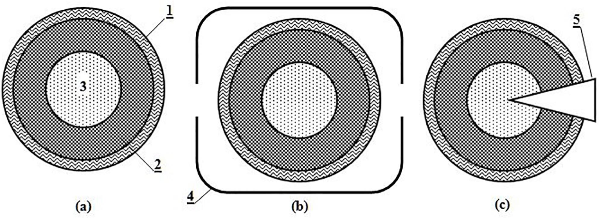
    This means that the development of the fuel-layering techniques is an inherent step for any IFE target design including both direct-drive (DD) and indirect-drive (ID) targets, and fast ignition (FI) ones (Figure 1).

    In conventional (‘central hot spot’ scenario) inertial confinement fusion (ICF), there are two basic target designs for ignition – capsules directly illuminated by the laser [DD experiments on the Omega laser at the University of Rochester’s Laboratory for Laser Energetics (LLE, USA) to elucidate the target physic[9]] and capsules driven by x-rays in a high-$Z$ cylindrical hohlraum (ID experiments on the NIF and LMJ to demonstrate ignition[4, 8, 10]). In addition, there is also a modified approach called FI, in which compression is separated from the ignition phase[1, 1115].

    All ignition target designs contain a fuel core (Figure 1): solid D–T fuel (equilibrium mixture of 50% deuterium and 50% tritium, having the molecular composition 25% $\text{D}_{2}$, 50% deuterium tritide molecules, and 25% $\text{T}_{2}$), which is smoothly layered on the inside of a spherical low-$Z$ ablator (plastic shell or capsule). This spherical D–T layer is surrounding a low-density D–T vapor at the triple point temperature or slightly below it.

    The manufacturing requirements for all NIF targets are extremely strict. The fuel layers have to be highly uniform with respect to thickness and roughness[16]. The desirable thickness uniformity $\unicode[STIX]{x1D700}_{1}$ is less than 1%, and the inner surface roughness $\unicode[STIX]{x1D700}_{2}$ is less than 1 $\unicode[STIX]{x03BC}\text{m}$ root mean square (rms) in all modes. The fuel must be isotropic to assure that fusion will take place.

    To realize the uniform conditions, different methods are applied as a fuel-layering technique, and the layer quality and the layer structure are known to depend on the method applied. In the conventional approach, known as beta-layering[17], extremely slow cooling ($3\times 10^{-5}~\text{K}/\text{s}$) is required to obtain layers like a single crystal and avoid the formation of multiple crystals of different orientations. The beta-layering process for forming these layers has been studied in many laboratories (experiments on the Omega, NIF and LMJ laser facilities). The total layering time is about 24 h which is a current average when considering different literature sources[1722].

    The surface roughness of the solid D–T fuel in a spherical ignition target is a critical parameter in determining the target performance. Therefore, some other techniques have been proposed and examined. A way to smooth an ice fuel layer is to cause heat to flow across the gas–solid interface. This heat flux can be generated by applying an electric field to the D–T vapor in the center of the shell. This technique is called joule (J) heating[23]. The second technique, infrared (IR) heating, uses monochromatic IR radiation to selectively excite rotational–vibrational bands of specific molecular hydrogen isotopes[2328]. This technique causes a volumetric heating of the ice layer and is similar to the beta-layering smoothing technique. In addition, the IR irradiation may be used to enhance the beta-layering: more rapid layer fabrication, formation of a smoother layer surface, elimination of the long-length perturbations from the anisotropic temperature environment caused by a cylindrical hohlraum. Besides, IR heating is the only known solid-layering technique for nontritiated hydrogen.

    A comprehensive review of different target designs and existing layering techniques is presented in Ref. [24]. Below we consider some special features of the conventional approach – beta-layering technique for a detailed understanding of its prospects for NIF ignition experiments and future IFE target fabrication.

    Currently, the D–T layer is condensed into the ablator shell and grown from a single seed crystal to eliminate the local defects. Both beta-layering and single seed crystal growth require a precise cryogenic temperature control (${<}1$ mK). The ice-layer growth is driven by fuel sublimation–condensation because the D–T is locally self-heated due to the thermal energy release from the beta-decay of tritium. Local heating raises the temperature in thick areas of D–T layer relative to thin areas, which leads to D–T sublimation from thicker (warmer) areas and condensation in thinner (colder) areas (ice-layer growth).

    The beta-layering forms very smooth and uniform solid D–T layers using ‘slow cooling’ and ‘rapid cooling’ protocols[21, 29]. At 0.25 K below the D–T triple point temperature ($T_{\text{tp}}=19.79$ K), slow-cooled layers meet the NIF smoothness requirement. However, the target before the shot must be at $T=18.3$ K to decrease the D–T saturated vapor pressure to $0.3~\text{mg}/\text{cm}^{3}$ for avoiding Rayleigh–Taylor instabilities during the implosion process. In other words, the target must be cooled down to $T_{\text{tp}}\sim 1.5$ K. Rapid cooling of the fuel layers at rates of 0.0–0.5 $\text{K}/\text{s}$ is promising to meet the ignition requirements. But the target lifetime (layer roughness is less than 1 $\unicode[STIX]{x03BC}\text{m}$ rms) is of a few seconds after reaching the desired temperature[21]. Thus, the beta-layering is efficient quite enough in forming a spherical layer in the isothermal capsule, but not efficient in preventing the local defects, so-called ‘grooves’. This is the implication of the fact that D–T layer (formed by the beta-layering) is obtained as a result of almost equilibrium process of the crystal growth, and all the features of the equilibrium crystalline state will be inherent in such a layer, including the temperature-dependent behavior of the local defect on the inner surface of the D–T layer. Decrease in temperature down to 18.3 K (rapid cooling protocol) has to be so rapid (in comparison with time of structure response for thermal influence) to provide a sufficient target lifetime before the laser shot because the change in temperature is a high activity catalyst for stimulate ‘grooves’ dynamics. Here we summarize the literature data related to the beta-layering technique:Long-run beta-layering process at very strict isothermal conditions (target temperature must be controlled down to 1 mK precision) requires about 24 h for one attempt. But routine practice is between 1 and 4 attempts, or even 6 attempts[22, 29], which generally requires several days or a week. As a consequence, we can conclude the following:

    The method is not efficient to maintain acceptable tritium inventory (for D–T at 19 K, a characteristic constant of the beta-layering is 27 min and increases with decreasing temperature or with increasing concentration of $^{3}\text{He}$ gas[24]).

    The method is not efficient for mass target fabrication for IFE (i.e., beta-layering is one-of-a-kind technique).

    The method is not efficient for repetition-rate fabrication and delivery of the target because all of the experiments on the NIF or Omega laser facilities require a target precisely located in the center of the target chamber. At the present-day experiments, a target support (be it the fill tube or any support to attach the target), for example, at the center of the layering sphere (laser-driven DD at OMEGA in the United States[9], FI at GEKKO XII in Japan[1, 13]), or at the center of a hohlraum (laser-driven ID at NIF in the United States[21, 22, 24], at LMG in France[7, 8], and in Russia[30, 31]) is an essential element for the beta-layering technique. For definiteness, we give a quote from the work[22]:

    Cryogenic equipment requires that targets be filled through the fill tubes.

    After adjustment of the fill, the liquid in the capsule is rapidly frozen creating an ice plug in the fill line that locks in the fill tube.

    The resulting ice is polycrystalline with many small crystals.

    To reduce the number of crystals, the solid is melted into the fill tube and then the remaining ice in the fill tube is allowed to grow back into the capsule.

    The seed growing into the capsule is usually an unstable face-centered cubic (FCC) seed which converts to a few hexagonal close-packed (HCP) crystals.

    This solid is again melted leaving as little solid as possible in the capsule to form the seed for layer growth.

    The remaining liquid is frozen by cooling this seed to form the layer.

    The crystal growth is dependent on the environment around the target, the dimensions of the target and the layering sphere, and the amount of D–T inside the capsule.

    As was noted in Ref. [29], the lifetime of the target produced by the beta-layering technique is only several seconds at $T=18.3$ K. This gives rise to additional problems in realizing the experiments with such a degree of perfection and accuracy that is required for ignition-level target performance:

    Firstly, for laser-driven DD targets, an important role can play many factors such as effect of the target support on ice-layer quality, fast shroud retractor for the cryostat, vibration control, target alignment, and so forth.

    Secondly, the target characterization is made at $T\sim 18.7$ K after the D–T layering was finished. But, the target temperature before the shot must be at $T=18.3$ K, i.e., after layer characterization, the target must be cooled down, and someone must be fully confident that just before the shot a desirable crystal structure and quality remain the same.

    In addition, the single crystals with anisotropic HCP structures formed by the beta-layering technique in terms of current and future applications (e.g., in reactor-scaled targets) generate serious problems relevant to the target quality survival under different environmental effects. This concerns the survivability of fuel layers with different anisotropy under conditions of the thermal and mechanical overloads during target delivery. For example, the calculations performed in Ref. [32] have shown that isotropic ultra-fine fuel layers can withstand higher heat loads than the anisotropic D–T solids crystallizing in the HCP phase. In addition, the nonequilibrium molecular dynamic simulations[33] have shown that ‘…nanocrystalline NIF targets would guarantee small fluctuations in the shock front, decreasing the probability for unwelcome instabilities’.Finally, current ignition targets formed by the beta-layering technique are at a high cost:

    ‘One-of-a-kind capsules produced for today’s ICF experiments are estimated to cost about US$2500 each. Design studies of cost-effective power production from laser and heavy-ion driven IFE have suggested a cost goal of about $0.25–0.30 for each injected target (corresponding to ${\sim}10\%$of the ‘electricity value’ in a target)’[34].

    ‘…the cost of targets has a major impact on the economics of inertial fusion energy power plants. Very large extrapolations are required from the current state of the art for fabricating targets for ICF research to the ability to mass-produce inexpensive targets for inertial fusion energy systems[35].

    All these require a systematic approach to develop a new R&D program for studying the factors that have an impact on the results of the current experiments because the ignition should be demonstrated before progressing to the first power plant.

    2 Mass production of ICF/IFE targets

    One of the central tasks in the IFE reactor program is the development of the production line operating with a massive of the free-standing targets (FSTs).

    The main steps of this production line have been investigated over the period of 1995–2016. They are as follows: mass production of shells[34, 3641], shell coating with protective layers[4245], fuel filling[30, 31, 44, 46, 47], cryogenic fuel layering[45, 46, 48, 49], target acceleration and injection[47, 5057], flying target tracking and shooting[50, 5763]. It is supposed that the first power plants will work with radioactive D–T fuel, which is a major limitation to IFE. Therefore, each production step of the target supply process must be completed on a minimal time and space scale and on very economic basis, meaning that all the production steps have to be optimized relative to the tritium inventory.

    Below we discuss the issues concerning the evaluation and recommendations of scalable techniques for mass production of the foam shells and the cryogenic targets.

    2.1 Mass production of the spherical foam shells

    The foam shell is an integral component of the IFE target design. The materials under consideration are divinyl benzene (DVB), poly-methyl-methacrylate (PMMA) and resorcinol formaldehyde (RF) foams as well as polyvinyl phenol (PVP), glow-discharged polymer (GDP) and polyvinyl alcohol (PVA) gas barriers. Significant advances have been made toward demonstrating production of mass capsules in leading IFE laboratories. The IFE capsules are complicated, precision assemblies, often requiring novel material structures.

    The General Atomics and Schafer Corporation are the prime target fabricators in the US ICF program since 1992[6466]. They supply ICF/IFE experiments with many thousands of targets and components each year, including the shells from beryllium, glass, bulk polymers, polymer and metal foams, barrier layer coatings, and so forth[65]. The technology to form reactor-scaled foam shells from DVB is discussed in detail in Ref. [67]. The main approach to the production of the polymer foam capsules is the microencapsulation technology. Using a multiple orifice droplet generator this technology can produce the capsules at high rates. The current production rate of the reactor-scale foam capsules from DVB is about 3 Hz (4 mm diameter and 200–300 $\unicode[STIX]{x03BC}\text{m}$-thick, the cell dimensions is 1–4 $\unicode[STIX]{x03BC}\text{m}$, the density is in the range of 15–200 $\text{mg}/\text{cm}^{3}$)[34, 44] (Figure 2). Thin gold and/or palladium coating can then be added on to the outer surface of the foam shell through a vapor deposition process (sputter coating)[34]. This Au/Pd coating is about 30–100 nm thick. Note that application of Pd as an outer coating greatly increases the shell wall permeability thus allowing rapid filling with $\text{D}_{2}$ and D–T fuel[34, 68].

    Step 1: dispense fluids and combine them to make an oil–water emulsion.Step 2: center the emulsion using an electric field and polymerize the shell.Step 3: remove fluid from the polymerized shell.

    The experiments[72] have demonstrated that application of the electric field at Step 2 has certain prospects to produce a spherically symmetric liquid shell (Figure 3). Further experiments are in the progress.

    An active research IFE program has been started in Japan[38] with respect to developing the mass technology of the FI targets. The current shell technologies allow fabricating thin polymer shells in a wide range of diameters (0.5–5.0 mm) as well as making thin plastic shells with a thick inner foam layer [Figures 4(a) and 4(b)][37, 38]. Figure 4(b) demonstrates a section of the foam PMMA shell with the outer PVA coating. The shell is made by the emulsion method with further deposition of the outer gas barrier by the interfacial poly condensation method.

    The FI target includes two components: the guiding cone and the shell with a special hole for the cone entrance. The mass manufacturing technique of the re-entrant cone fabrication has been demonstrated in the United Kingdom and Japan[3840]. In Ref. [38], it was proposed to make cones from Li17Pb83 (which is the same material as the first wall of the reactor chamber) because of lower erosion and higher mechanical strength of this material compare to the pure lead. The original method of drilling of frozen foam shells to make a hole for the re-entrant cone followed by the cone-and-shell assembly has been demonstrated in Japan for an individual target[38]. Mass fabrication of the re-entrant cones using the mechanical micro-machining system is also developing in the United Kingdom[39, 40] (see Figure 5 taken from Ref. [39]).

    One of the topical problems of the target fueling is a rapid loading of the shell batch with a fuel. Study on cryogenic injection filling (liquid fuel) versus diffusion filling (gaseous fuel) is required.

    So the current technologies are mainly of two types: liquid fuel filling and gaseous fuel filling.

    Liquid fuel filling:

    The first approach is based on the fuel loading through a thin tube mounted onto a shell. A small hole of about 5–15 $\unicode[STIX]{x03BC}\text{m}$ diameter is drilled in a shell wall, and the tube is mounted to the shell. The shell is then cooled and the liquid fuel is filled through the tube. This approach is used in many ICF Laboratories; for example, in the present-day cryogenic experiments on the NIF for fueling the ignition individual targets[66] as well as in the cryogenic experiments on the freezing of hydrogen isotopes, performed in Russia[30].

    The second approach is based on the fuel loading to a foam shell by the thermal cavitation technique[47]. The steps of this technique for a batch of the FI targets are as follows:

    A batch of foam targets with re-entrant cones are placed into a bath with liquid D–T fuel.

    The liquid fuel fills each target through the pores of the target wall.

    Laser light is introduced into the inner volume of each target through a re-entrant cone.

    Inner volume of the targets is evacuated by laser heating.

    This approach has been demonstrated with a foam hemi sphere filled with the liquid $\text{D}_{2}$[47].

    Gaseous fuel filling by diffusion through a shell wall. The fuel gas is permeated through the wall in a controlled manner to prevent the wall buckling:

    The first approach is based on filling an individual shell mounted in the permeation cell. This approach is applied for the target preparation for ICF experiments on the OMEGA laser[74]. The fuel gas is permeated through the wall in a controlled manner to prevent the shell wall buckling. The cell is then cooled to ${\sim}20$ K or below to condense/freeze the gas.

    The second approach is based on filling a batch of free-standing shells at one time[31, 46, 75] (see Section 3.2), which allows to shorten the fill time per target. The shells are placed in the shell container (SC). The diffusion technique can work in molecular or atomic (more rapid process) modes. Comparative characteristics of the both processes were studied in Refs. [68, 75]. After filling at 300 K, the SC with the filled shells is transported at the same temperature from the fill system to the layering module (LM) for carrying out the experiments on FST layering.

    Before starting the experiments, the SC is cooled down to a temperature $T_{\text{d}}$, which is significantly lower than 300 K. This is required for the SC depressurization, i.e., for the gas removal from the dead volume of the SC. The possibility of performing the procedure of SC depressurization under conditions excluding both the shell breakdown by internal pressure and the fuel leakage from the shells due to the reverse diffusion appears only under the temperature decrease: when the gas pressure drops down, the gas permeability decreases, and the strength of shell material rises. As the gas pressure in the shell does not depend on the shell material, the possibility of performing one variant or another is determined only by the shell strength and the value of its aspect ratio. In principle, two situations are possible: at a certain temperature, the tensile strength of the shell is sufficient to depressurize the SC when the fuel is still gaseous, or a necessary diminishing in pressure can be achieved only at $T_{\text{d}} ($T_{\text{cp}}$ is the critical point temperature), when the fuel in the SC becomes liquid. This determines the initial fuel state before FST layering: (1) gaseous state corresponds to $T_{\text{d}}>T_{\text{cp}}$, (2) critical state corresponds to the critical point region $T\sim T_{\text{cp}}$, (3) liquid state corresponds to the compressed liquid region at $T_{\text{s}}, (4) two-phase state corresponds to the ‘liquid $+$ vapor’ state at $T$${<}$$T_{\text{s}}$, where $T_{\text{s}}$ is the temperature of the fuel separation into the liquid and gaseous phases.

    The diffusion technique to ramp fill a batch of free-standing shells at one time with a highly pressurized fuel gas (up to 1000 atm at 300 K) was developed and practically realized at the Lebedev Physical Institute, Russian Academy of Sciences (LPI/RAS)[31, 46, 75].

    2.2 Mass production of the cryogenic targets

    To solve the problem of mass production of the cryogenic targets, two approaches are considering: fluidized bed layering (USA, General Atomics[34, 44, 54, 7678]) and foam layering (USA[44, 79, 80] and Japan[81, 82]).

    Fluidized bed layering technique is an attempt to form the cryogenic D–T layer of an acceptable quality inside a batch of unmounted shells using the beta-layering process. The following sequence of operational steps is applied[54, 7678]:

    A batch of unmounted shells is placed inside a pressure vessel and it is filled there with gaseous D–T fuel by a diffusion process.

    While still in the pressure vessel, the targets are cooled below the triple point of D–T (19.79 K), which is followed by D–T fuel condensing and freezing on the bottom of the shells.

    Then the shells are transported into a fluidized bed, where the batch of unmounted shells begins to levitate in a rising flow of gaseous helium. It should be noted that gas pressure in the bed has to be low enough not to crash the thin-walled targets.

    During this process, nonuniformly frozen D–T form a uniform solid layer inside the shells according to the beta-layering process[21]. Note that for smooth and uniform fuel layer formation using the beta-layering it is required that the isothermal environment around a target be better than ${<}1$ mK. A near-isothermal environment has to be maintained around each target in the fluidized bed through the random movement and spin of individual targets within a precisely controlled gas stream.

    Operation of the fluidized bed with a massive of Au/Pd-coated PAMS at $T<10$ K was demonstrated in Ref. [54] (Figure 6). Unfortunately, the experiments have shown that some of the shells are crushed as they bump each other during their levitation in the fluidized bed. This is a problem that must be solved. In addition, all the problems inherent to the beta-layering process will be inherent to the fluidized bed layering as well. Difficult and expensive technologies such as precision control of temperature, pressure and thermal uniformity of the environment are necessary during seed formation and D–T layer growth to create a really groove-free single crystal layer. Nevertheless, this method is being studied in the United States as a promise for mass production of IFE targets [7678].

    Foam layering technique is another approach, which is under consideration in the research laboratories of the United States and Japan[44, 7982]. In this approach liquid fuel layer is distributed inside the foam capsule into a spherically symmetric layer due to an action of surface tension of the foam. Unfortunately, the application of foam capsule allows retaining liquid fuel in uniform configuration until the pores are not supersaturated. Note that according the calculation results given in Ref. [80] it is necessary for the efficiency of the DD scheme that foam layer be supersaturated with 280 $\unicode[STIX]{x03BC}\text{m}$ thick pure D–T layer disposed over the inner surface of the foam capsule. The spherical uniformity of pure liquid D–T layer is disrupted under an action of the gravity. Probably, this problem can be solved by the magnetic levitation technique[83]. On the other hand, the calculations[79] have shown that it is possible to optimize target parameters so that it would be possible to use, rather effectively, targets in which a porous layer is not supersaturated.

    One of the critical issues of the foam layering is the following. During the process of liquid-to-solid fuel transition, the fuel density becomes higher; thus small voids arise in each pore. This results in the emergence of a fuel inhomogeneity in the layer volume.

    A new concept for reactor targets mass production has been proposed in the United States[41, 69]. It is based on programmable microfluidic electromechanical circuity to govern the processes of the foam shell fabrication, the shells filling with liquid fuel and targets transport. The feasibility of this concept to form the cryogenic D–T targets is being investigated in Refs. [41, 69] according to the following layout: (1) form liquid D–T into discrete droplets; (2) wick liquid into the foam shell (foam layering); (3) condense inert gas (Ne, Ar, Kr or Xe) onto an outer surface of foam target. An overcoat from solid inert gas serves as a barrier coating onto a foam; (4) form solid fuel layer when the target moves through a thermal gradient (from 20 to 19.5 K) at a rate of 0.001 K per 5 min; (5) inject target: an overcoat from solid inert gas ablates during target flight, and thus protect the target from overheating.

    The experiments[41, 69] showed the liquid $\text{D}_{2}$-column levitation in the capillary under the action of electrostatic field followed by forming a droplet of the desired volume (Figure 7), and the liquid $\text{D}_{2}$ wicks completely and rapidly into the foam shell. It was found that developing a viable condensed-gas overcoat of the foam shell is critical to simplifying the D–T filling and target injection operation. The advantage of the microfluidics approach is that it ensures a faster fuel filling and thus reduces the tritium amount during target preparation. On the other hand, the layering time is still large: the process requires D–T layer cooling from 20 to 19.5 K with a rate of 0.001 K per 5 min[69]. Besides, there exist some open questions concerning a protective layer (overcoat), namely:

    Which is the required thickness and composition of the overcoat?

    Is the overcoat sublimation uniform enough during target injection?

    The above questions require additional study.

    As regards the application of the overcoat from a solid inert gas, it should be noted that the issue has a certain history. Such protective layers were first proposed by Hendrics and Johnson in 1979[42]via condensation of the inert gas on the outer surface of free-falling spherical shells from the solid fuel. A schematic of the facility, so-called a multilayer cryogenic reactor, is shown in Figure 8.

    Another approach to form the outer protective cryogenic layer from a solidified gas has been proposed and demonstrated in Refs. [43, 84]. In these experiments a special rotating-and-bouncing cell (R&B cell) was used. Deposition of the outer protective cryogenic layer onto the target is presented in Figure 9, in which Figure 9(a) shows two polymer shells inside the R&B cell prior to the experiment. Exceptionally for the purposes of illustration, we set the experiment in the following way. Each shell encloses liquid $\text{H}_{2}$ at 14.6 K, which is readily seen at the bottom of each shell. In the top part of the shells (from the outside) there is a solid deposit of oxygen. After the R&B cell operation in the mixing mode the solid deposit becomes redistributed sufficiently uniform onto the outer surface of both shells [Figure 9(b)]. Note that under experiment conditions the shell #1 has a Pd coating of 15 nm thick, which is important for additional target protection. Allowing for the obtained results (opaque protective layer), we propose the following physical layout of the target formation with a protective cryogenic layer from the outside: filling the shell with gas, formation of the inner fuel layer, target characterization, and if the target is within the specifications, deposition of the outer protective cryogenic layer.

    There are also other researches[85] in which it has been theoretically proven that an outer ‘insulating’ foam layer provides an increased thermal robustness during the target injection into the target chamber. Inclusion of an empty plastic foam layer on the outside of the target provides thermal insulation that would delay the heat transfer to the D–T fuel and helps extend the target lifetime during injection.

    Closing this section, note that the fluidized bed layering and the microfluidic concept are currently at the beginning stage of their development. The next step is to demonstrate these approaches with spherical targets filled with $\text{D}_{2}$ and D–T fuel. This means that all of the basic processes for target fabrication must be demonstrated though for individual targets (fuel filling, D–T layering and characterization of the D–T layer, cryogenic transfer, etc.). Changing to a mass target production (with accounting the interface problems) will be extraordinarily challenging for both techniques.

    Long layering time (under the cooling rate of 0.001 K per 5 min).It becomes impossible to deliver the targets with anisotropic fuel into the reaction chamber without roughening of the layers[32, 86].Anisotropic fuel can lead to a distortion of the front of a shock wave (growth instabilities caused by grain-affected shock velocity variations). As shown in Ref. [33], nanocrystalline NIF targets would be the best for their application for achieving efficient ignition.

    3 High-repetition-rate production of ICF/IFE targets

    IFE cannot be a real energy source unless the cryogenic targets can be economically fabricated at a high rate and precision. Taking advantage of significant previous research (USA[34, 41, 42, 44, 54, 69, 7680], Japan[81, 82], Europe[83], Russia[46, 52, 75, 8699]), future work in this direction must include IFE-scale target science and technology development and demonstration.

    High-repetition-rate IFE-scale target science and technology comprises target fabrication, injection and tracking. Critical issues for IFE target fabrication are identified as follows:Mass target production to ensure the fueling of a commercial power plant at a rate of 5–10 targets each second.Requirements of implosion physics to the layer structure:Minimization of time (including the layering time) and space for all production steps in the target system to minimize the tritium inventory and to supply targets at the low cost required for economical energy production.

    To meet these conditions, different methods are applied as a fuel-layering technique, and the layer quality and the layer structure are known to depend on the method applied.

    Currently, many R&D programs on layering method development are being conducted but not with the emphasis on the high-repetition-rate target production. Recall that the beta-layering method (which is a base for NIF targets[21], and for layering of IFE targets using a fluidized bed[77]) requires extremely slow cooling (${\sim}3\times 10^{-5}~\text{K}/\text{s}$) to avoid the formation of multiple crystals of different orientations and to obtain an equilibrium fuel state like a single crystal.

    In the equilibrium state, the solid hydrogen isotopes consist of anisotropic molecular crystals, and survivability of the fuel layers subjected to the environmental effects may depend on the layer structure. As found in Ref. [100], anisotropy ($\unicode[STIX]{x1D709}$) of the sound velocity ($V_{\text{s}}$) is inherent to the HCP phases of $\text{H}_{2}$ and $\text{D}_{2}$, and it makes more than 20%. In accordance with the Debye theory, the factor of the thermal lattice conductivity is in a direct proportion to the value of $V_{\text{s}}$. Therefore, even under uniform target heating (e.g., radiative heating from the hot wall of the reaction chamber operating at temperatures as high as 1758 K, SOMBRERO chamber[36]), the normal temperature gradient to the inner surface of the anisotropic fuel layer becomes different in different points. This initiates the spherically asymmetrical sublimation of fuel in the target cavity, and results in the layer degradation with respect to roughness and thickness. Investigations initiated in Refs. [32, 86] have demonstrated that the fuel layers with anisotropy $\unicode[STIX]{x1D709}>10\%$ degrade in the SOMBRERO chamber due to roughening of the layer surface before the target reaches the chamber center (even at injection velocity 400 $\text{m}/\text{s}$). The calculations were performed for the target with a 4 mm diameter CH shell and a 45 $\unicode[STIX]{x03BC}\text{m}$ thick wall, the solid $\text{D}_{2}/\text{D}$–T layer thickness being $W=200~\unicode[STIX]{x03BC}\text{m}$.

    For anisotropic fuel layers with $\unicode[STIX]{x1D709}=7\%$–9% the injection temperature $T_{\text{ing}}$ becomes equal to 18 K, i.e., close to the temperature of 18.3 K, at which the target must have before the laser shot. This indicates that the target must be injected at much higher velocities that results in a long acceleration distance or occurrence of high mechanical loads during the injection process.

    If the design of the reaction chamber includes a fill gas, then the target is exposed to both uniform radiative heating and convective heating. In this case some issues associated with target injection becomes more complicated.

    For this reason, development of the layering methods that allows reducing the sensitivity of cryogenic layers to thermal and mechanical loads has been advanced. Accordingly, there has emerged a demand to clarify their structure–property relationships in order to understand the fundamental concepts underlying the observed physical and mechanical properties.

    3.1 Fuel layering in free-standing and line-moving targets

    Because the fusion reactor operates at significant rates, it will need to be refueled during its burn period, and an FST transmission line becomes an integral part of any IFE reactor[49, 87]. It must supply about one million targets each day and transport them to the reaction chamber.

    A key aspect of the target transmission line is elaboration of the efficient methods of cryogenic target fabrication. The targets must be free standing and the fusion fuel inside the targets must have such a structure (the grain size should be scaled back into the nanometer range), which supports the fuel layer survivability under target injection and transport through the reaction chamber. The ultra-fine fuel layers refer to as advance materials for application to fusion target fabrication in the form that meets the requirements of implosion physics[88].

    To meet the above requirements, at the LPI/RAS significant progress has been made in the technology development based on rapid fuel layering inside moving FSTs, which refers to as FST-layering method[46, 52, 75, 8699]. The aim of these targets is to demonstrate large benefits of a ‘layering – plus – delivery’ scheme for a rep-rated target fabrication and delivery (Figure 10). Thus, a fundamental difference of the FST-layering method from generally accepted approaches is that it works with the free-standing and line-moving targets (see Figure 10), which allows one to economically fabricate large target quantities and to continuously (or at a required rate) inject them at the laser focus.

    During FST layering, a batch mode is applied, and high cooling rates ($q_{\text{FST}}=1{-}50~\text{K}/\text{s}$) are maintained to form isotropic ultra-fine solid layers inside free-rolling targets. High cooling combined with fuel doping (neon, argon and tritium) results in creation of stable ultimate-disordered structures with a high defect density or isotropic medium. The effect of additives is as follows[88]:

    They initiate a mass dislocation growth that prevents the formation of a coarse-grained crystalline phase and enhances the mechanical strength of the layers.

    They decelerate the diffusion transport processes and raise the diffusion activation energy.

    They work as stabilizing agents keeping the grain size stable and, as a consequence, keeping the thermal and mechanical stability of the ultra-fine cryogenic layers.

    The results obtained for solid hydrogen samples[101] have shown that even a slight granularity growth (grain size decrease by a factor of 1.4) significantly increases the deformation strengthening coefficient along the entire deformation curve. The strength limit also increases by ${\sim}1.3$ times.

    In addition, the important parameter is the following value: target lifetime on a temperature scale $\unicode[STIX]{x1D6E5}T$, which is the temperature interval in which a stable ultra-fine layer structure can exist. Our experiments showed that for FST technology this interval has the largest possible range, from 4.2 K right up to the temperature of solid fuel melting at the triple point[75, 90, 93].

    Therefore, the ultra-fine layers obtained by FST can be referred to as layers with inherent survival features because they have enhanced mechanical strength and thermal stability[32, 86, 94]. This is a significant factor for layer quality survival during the target delivery.

    The term ‘ultra-fine’ layer relates to a fuel state, which is characterized by an ultra-fine microstructural length or a grain size. It can be classified into the following structural categories: near-nano (submicron) crystalline state (grain size in the range of 0.1–0.3 $\unicode[STIX]{x03BC}$m), nanocrystalline state (typically, grain size ${\leqslant}100$ nm), amorphous state (characteristic spatial scale or the order parameter ${\sim}1$ nm). Very often, near-nanocrystalline state is called ‘fine-grained’ crystalline. The properties of nanostructured materials deviate from those of single crystals (or coarse-grained crystalline) and glasses with the same average chemical composition. Nanocrystalline materials and coatings are a challenging research topic at the LPI/RAS in the area of target science and technology[87].

    The FST-layering method is promising for the formation of a stable ultra-fine layer from D–T mixture having the molecular composition: 25% of $\text{D}_{2}$, 50% of deuterium tritide molecules, and 25% of $\text{T}_{2}$ ($\text{T}_{2}$ in D–T is considered as a high-melting additive with respect to $\text{D}_{2}$ and deuterium tritide).

    3.2 FST-layering experiments according to the scheme of ‘layering $+$ delivery’

    With contributions from leading works, this section reviews the most up-to-date progress in the development of the FST-layering method. During FST layering, two processes are mostly responsible for maintaining a uniform solid layer formation:

    Firstly, the target rotation when it rolls along the layering channel (LC, single- or double-spiral) results in $a$liquid layer symmetrization.

    Secondly, the heat transport outside the target via conduction through a small contact area between the shell wall and the wall of the LC (metal hollow tube helium cooled outside) results in a liquid layer freezing.

    The total layering time is typically less than 15 s, which has a side benefit in the view of tritium inventory minimization[46, 75, 91, 92, 95, 98, 99]. The LC is a major element, which ensures the target technology development according to the ‘layering $+$ delivery’ scheme. Figure 11 schematically shows the operational scenario of the FST-layering method which includes:

    FST- LM works with a target batch at one time.The transport process is the target injection between the basic units of the LM: SC, LC and test chamber (TC).During moving, the target surface is not isothermal.Targets move top-down in the LC (Figures 1113) in a rapid succession of one after another.All these allow a high-repetition-rate injection of the cryogenic target to the TC.TC is used for cryogenic target quality control: precise tomographic characterization[75, 102104] and threshold characterization[75, 105].TC is a prototypical interface unit between the LM and target injector (TI).

    The LC is a special insert into the LM cryostat (Figure 14), a certain part of which must be at cryogenic temperatures. For successful experiments, the medium immediately surrounding the target inside the LC is vacuum, which is promising for creation of the interface units. Several interchangeable LC – cylindrical (wide and narrow under vertical and inclined geometry) and spiral – were manufactured and tested. Note that FST layering does not require that the target surface be near to isothermal.

    ParametersValues
    $H_{01}$ – upper end of spiral 16 cm
    $H_{02}$ – upper end of spiral 20 cm
    $R_{1}$ – radius of spiral 112 cm
    $R_{2}$ – radius of spiral 212 cm
    $H_{1}$ – height of spiral 165 cm
    $H_{2}$ – height of spiral 245 cm
    $H_{\text{CLC}}$ – total height of CLC $(H_{01}+H_{1}+H_{2}+H_{01})$1.16 m
    $t_{\text{CLC}}$ – total time of target rolling $(\unicode[STIX]{x1D70F}_{\text{res}})$14.9 s

    Table 1. Design specifications calculated for CLC with two spirals (for the time $\unicode[STIX]{x1D70F}_{\text{res}}\sim 15$ s).

    The LC must have a well-defined geometry in order to satisfy the condition: $$\begin{eqnarray}\unicode[STIX]{x1D70F}_{\text{form}}\leqslant \unicode[STIX]{x1D70F}_{\text{res}},\end{eqnarray}$$  where $\unicode[STIX]{x1D70F}_{\text{form}}$ is the layering time and $\unicode[STIX]{x1D70F}_{\text{res}}$ is the time of target residence in the LC. A key problem for this condition realization is the determination of the LC parameters: the spiral angle ($\unicode[STIX]{x1D6FC}$ is inclination angle), the total spiral length $(L)$, the number of spiral turns ($\unicode[STIX]{x1D6FA}$) and one-turn diameter ($\varnothing$). A set of the single-spiral and double-spiral LCs is shown in Figure 12. The double-spiral LC are our latest developments in the area of optimization of the FST-layering process for the fabrication of cryogenic targets with a diameter over 2 mm[95, 96, 99] because they maintain the gain in the target residence time and fuel layer symmetrization. The mock-up testing revealed a considerable increase in the value of $\unicode[STIX]{x1D70F}_{\text{res}}$ inside a double-spiral LC with respect to that of a single-spiral one. For example, for the single- and double-spiral LC with the same parameters ($\unicode[STIX]{x1D6FA}=23$ turns, $\varnothing =38$ mm, $L=400$ mm, material: cuprum tube $\varnothing 6.3~\text{mm}\times 0.75$ mm) the values of $\unicode[STIX]{x1D70F}_{\text{res}}$ were 9.8 and 23.5 s in Figures 12(b) and 12(c) (LC No.1). The LC No.2 in Figure 12(c) has practically the same parameters: $\unicode[STIX]{x1D6FA}=22$ turns, $\varnothing =39$ mm, $L=440$ mm, material: cuprum tube $\varnothing 6~\text{mm}\times 1$ mm, but the spiral angle slightly varies along the spiral length. In doing so, we can scale up or scale down the target speed during its rolling in the LC. One of the most interesting cases is a CLC, which consists of two spirals (Figure 13): acceleration spiral (spiral 1, red coiling) and deceleration spiral (spiral 2, blue coiling) in order to zero the target speed at the combined LC (CLC) output[87]. The problem formulation is as follows: determine the CLC parameters for the target residence time $\unicode[STIX]{x1D70F}_{\text{res}}\sim 15~\text{s}$, for the inclination angle of spiral 1 $\unicode[STIX]{x1D6FC}_{1}<13^{\circ }$ (to realize just the rolling motion without any sliding), for the inclination angle of spiral 2 $\unicode[STIX]{x1D6FC}_{2}\sim 0^{\circ }$ and for the total height of the CLC ${\sim}1$ m. The computation results are presented in Table 1.

    FST layering Performance data Meeting the requirements
    High cooling rates 1–50 $\text{K}/\text{s}$Isotropic ultra-fine fuelShock wave propagation via isotropic fuel layer
    Minimal layering time ${\sim}15$ sTritium inventory minimization
    High-melting additives 0.5%–20% Grain size stabilization Acceptable surface finish
    High mechanical strength & High thermal stability Target survival during delivery
    Fuel layering in rolling FSTs Uniform layer formation Acceptable target quality
    High-repetition-rate fabrication and injection Mass production and sufficient price

    Table 2. Isotropic ultra-fine fuel for application to IFE targets fabrication[88].

    OMEGA: $E=30$ kJNIF: $E=1.5$ MJ
    Target parameters ($\unicode[STIX]{x03BC}\text{m}$)Layering timeTarget parameters ($\unicode[STIX]{x03BC}\text{m}$)Layering time
    $R$460$T_{\text{in}}=37$ K$R$ 1690$T_{\text{in}}=37$ K
    $\unicode[STIX]{x1D6E5}R$3$\unicode[STIX]{x1D6E5}R$ 3
    $W$1004.8 s$W$ 34030.9 s
    HiPER: $E\sim 200$ kJ ($\unicode[STIX]{x1D708}\geqslant 1$ Hz)
    BT-2 ($\unicode[STIX]{x03BC}\text{m}$)Layering timeBT-2a ($\unicode[STIX]{x03BC}\text{m}$)Layering time
    $R$1047$T_{\text{in}}=37$ K$R$ 1023$T_{\text{in}}=37$ K
    $\unicode[STIX]{x1D6E5}R$3$\unicode[STIX]{x1D6E5}R$ 3
    $W$21113.8 s$W$ 1209.7 s
    $W_{p}$$W_{p}$ 70
    ‘Nakai’ target[106]: $\unicode[STIX]{x1D708}>5$–10 Hz
    Target parameters ($\unicode[STIX]{x03BC}\text{m}$)Contact area/shell surface ratio $\unicode[STIX]{x1D712}$aLayering time
    $T_{\text{in}}=37$ K$T_{\text{in}}=27$ K
    $R$2000
    $\unicode[STIX]{x1D6E5}R$45$\unicode[STIX]{x1D712}=1.8\times 10^{-3}$ (CH shell only)227.5 s149.0 s
    $W$200$\unicode[STIX]{x1D712}=3.0\times 10^{-2}$ (CH shell $+$ metal coating)13.65 s8.94 s

    Table 3. FST-layering time for different targets[88, 99].

    Note that the CLC can be of any configuration (two or more spirals or including a conical one) as long as it provides the required layering time and fuel layer symmetrization. We also plan experiments on the FST layering within the LC like a three-leaved figure (trefoil) in the cross-section. All these allow the formation of cryogenic targets of different designs by the FST-layering method (Tables 2 and 3)[88, 99, 106].

    The physical layout of the FST-formation cycle (fuel filling – fuel layering – target injection) is as follows:

    Fuel filling of a shell batch placed in the SC (CH shells used at LPI/RAS are shown in Figure 15).

    SC transport from the fill system to the LM (Figure 14).

    SC cooling and depressurization without shell destruction.

    Shell injection one by one from the SC to the LC.

    FST layering within moving FSTs inside the LC (layering $+$ delivery).

    Repetition-rate injection of the finished cryogenic targets to the TC from the LC, the bottom part of which is a gravitational injector[94].

    Scientific reasons for the concept of cryogenic target transport by injection in the course of its fabrication and delivery at the laser focus were given in Refs. [107109]. The target injection can be carry out directly to the TC with a free target positioning onto the chamber bottom [Figures 16(a) and 16(b)] or to a special cylindrical cavity [Figure 16(c)]. Some other options for the target injection and positioning are demonstrated in Figures 1720. The target injection and positioning using a tripod [Figure 17(a)] was proposed and examined at the LPI/RAS[94] (Figure 20) for the 300 kJ laser facility (ISKRA-6[110]).

    A promising way is the possibility of using magnetic levitation (maglev) transport systems for noncontact manipulation, positioning and delivery of the cryogenic targets (Figures 17(b)–19). We focus on the transport system development based on movement of high-temperature superconductors (HTSC) over a permanent magnet guideway (PMG) systems[56, 57, 87, 111113]. An active guidance was achieved by using the HTSC ceramics ($\text{YBa}_{2}\text{Cu}_{\text{3}}\text{O}_{7-X}$, often abbreviated as Y123) and different PMGs. The HTSC materials allow working in two research lines: indirect delivery when the target is placed into a sabot (special capsule for target carrier) and direct delivery when target moves in a solo flight without any target carrier. The study is designed to generate different regimes of the HTSC sample levitation for testing the conditions that can be applied to development of Maglev transport systems. A prototypical HTSC-sabot (superconducting substrates) were used as a carrier for polymer (CH) shells in the presence of a magnetic field of different configurations [Figures 17(b1) and 17(b2)]. A special interest here will be to also see how the CH shell levitates in a solo flight without any support [Figure 17(b3)]. To do this we deposited an outer covering (Y123-layer) onto the outside of a 2 mm diameter CH shell. The Y123-layer is a composite from a viscous polymer having micro-particles (superconducting powder) from Y123-ceramics. The check, using which experiments have been executed, shows the FST facility (Figure 18) based on the optical helium cryostat of a closed cycle for levitation experiments below 20 K. Figure 19 shows the levitation of the system ‘CH shell $+$ Y123-layer’ at $T=80$ K and at $T=18$ K in the TC of the cryostat. It is notable that at all temperatures varying in the experiments from 6.0 to 80 K we obtain similar results on the HTSC sample levitation. It allows us to run the experiments on the development of the maglev transport systems at 80 K [Figure 19(b)], as such experiments are not available in the TC of the cryostat because of its small sizes (5 $\text{mm}^{3}$) [Figure 19(c)].

    In the IFE research, these results attract a significant interest due to their potentials for almost frictionless motion, i.e., the HTSC–maglev suspension technologies can be used for enhancement of the operating efficiency of an injection process. Thus, the HTSC–maglev transport systems, because of their contactless nature, can be an excellent springboard for the development of a hybrid TI[102].

    3.3 Hydrogen fuel with an isotropic ultra-fine structure

    Ultra-fine materials (near-nano and nanocrystalline) with new functionalities show great promise for application to IFE[114]. Substantial progress has been made in the past decade in developing target fabrication capabilities to form an ultra-fine hydrogen fuel[49, 87, 88]. Further discussion is required to review the structure–property relationships in order to understand the fundamental concepts underlying the observed physical and mechanical characteristics.

    Over the last 20 years, the LPI/RAS has been devising the structure-sensitive methods of forming high-quality hydrogen fuel layers with an isotropic structure to meet the requirements of implosion physics (see original papers[89, 90] and further developments[32, 46, 49, 75, 8688, 9399]). As shown, a considerable anisotropy of HCP phases of $\text{H}_{2}$ and $\text{D}_{2}$[100] results in the layer degrading due to roughening of the layer surface before the target reaches the chamber center, or can result in the shock velocity dependence on the grain orientation[32, 8688].

    Taking into account that the extent of anisotropy is 20% for longitudinal sound and 33% for transverse sound[100], the formation of isotropic solid fuel is of vital importance. In this context, the FST-layering method is a valuable tool to form isotropic ultra-fine cryogenic layers under the following conditions: high cooling rates ($q_{\text{FST}}=1{-}50~\text{K}/\text{s}$) combined with high-melting additives to fuel content in the range of $\unicode[STIX]{x1D702}=0.5\%$–20%. Figures 2123 illustrate the influence of these conditions on the cryogenic layer structure and quality.

    No additives are used in the experiments presented in Figure 21. Different cooling rates give rise to the cryogenic $\text{H}_{2}$-layer formation with a different granularity. Transparent cryogenic layers are formed only at extremely high cooling rates. They are more than $100~\text{K}/\text{s}$ (see on the right of Figure 21). In the next set of experiments conditions have been changed (Figure 22). Moderate cooling rates (only 2–10 $\text{K}/\text{s}$) were combined with using different additives to the hydrogen fuel. In addition, the metal outer coatings were deposited on the CH shells to balance the cooling conditions. The coatings were made from Pd [15 nm on the first two, Figure 22(a)] and Pt/Pd [20 nm on the last two Figure 22(b)]. Then these shells were filled with pure gaseous fuel and gaseous fuel having the doping agents: Figure 22(a): frame 1, pure $\text{H}_{2}$; frame 2, $\text{H}_{2}+5\%\text{HD}$; Figure 22(b): frame 3, pure $\text{D}_{2}$; frame 4, $\text{D}_{2}+3\%\text{Ne}$. Even frames (2 and 4) in Figure 22 show a significant influence of the applied additives on the hydrogen layering.

    In Figures 23(a) and 23(b), the amount of additives was 20% (Ne) in order to model the D–T fuel. The cooling rates are 8 $\text{K}/\text{s}$ for glass shell and 2 $\text{K}/\text{s}$ for CH shell. The tomographic characterization (100-projection micro-tomograph[104]) showed that the $\text{D}_{2}$ layers are spherical and smooth, meeting the specification requirements $\unicode[STIX]{x1D700}_{2}=0.15~\unicode[STIX]{x03BC}\text{m}<1~\unicode[STIX]{x03BC}\text{m}$ [Figure 23(c)]. We already note that the FST-layering method is much promising for the formation of a stable ultra-fine layer from D–T (25% of $\text{T}_{2}$) because $\text{T}_{2}$ is considered as a high-melting additive with respect to $\text{D}_{2}$ and deuterium tritide.

    Thus, fuel doping (high-melting additives with regard to the hydrogen isotopes and their mixtures) is the condition which answers to the practical realization of the FST-layering method for application to IFE. It is connected with the fact that, without additives the cryogenic layer formation of the required quality is possible only at very high cooling rates (${\geqslant}100~\text{K}/\text{s}$, Figure 21). For the creation of a reliable and inexpensive FST technology it is necessary to reduce the cooling rates by one and a half or even two orders of magnitude. Using the additives allows one to reach the goal.

    Further we try to formulate some basic aspects that illustrate the difference between the beta-layering method and the FST-layering method.

    The former requires slow cooling rates (${\sim}10^{-5}~\text{K}/\text{s}$) and high-temperature control (${<}1$ mK) for avoiding the formation of multiple crystals of different orientations, and for obtaining a single crystal layer (more exactly, a real single crystal and not ideal one) from anisotropic hydrogen isotopes. The layer growth usually starts with a single crystal seed. The process to grow up all the layer from this seed takes many hours, and the grain boundaries which roughen the layer surface can occur. In this case the layers become unstable relevant to the growth of local defects under thermal and mechanical loads, and can decrease the odds for achieving ignition at NIF.

    The latter requires the high cooling rates (${\sim}10^{2}~\text{K}/\text{s}$) and nonisothermal target to stimulate the occurrence of a tremendous amount of crystals of different orientations. This allows to reduce the grain size and suppress the fuel anisotropy. Moreover, near-nano and nanostructured materials exhibit some peculiar mechanical and physical properties, e.g., an increased mechanical strength[115]. These layers are assembled from the ultra-fine crystallites or building blocks. Since the grain sizes are sufficiently small, the grain boundaries make up a major portion of the materials, and strongly affect their properties. As shown in Ref. [116], it is possible to program the properties of such materials through the control of their structural features, more specifically the grain size, taking into account that their structure is mainly formed from the grain boundaries, and a large portion of the atoms resides in these grain boundaries.

    Thus, for the beta-layering method, changing the conditions under which the real single crystal layers are grown up stimulates the dynamic grain boundaries and results in local defect growths, so-called grooves (e.g., under thermal and mechanical loads in time between the moment just after target preparation and the laser shot).

    For the FST-layering method, the grain boundaries in the ultra-fine fuel layers allow to obtain many useful and unique thermal, mechanical, magnetic, electrical and optical properties[115, 116] which can be applied to enhance the target performance during implosion.

    At present stage, the R&D program at the LPI/RAS proposes to undertake a research effort, in which contemporary advances in physical and chemical engineering science on material structurization will be applied to accomplish specific technological tasks for further optimization of the FST-layering method. One more option to fuel material structurization is cryogenic layer fabrication in the conditions of periodic mechanical influence[117]. As is well known from literature[118120], existence of external periodic impacts on a liquid phase in the course of its crystallization allows to regulate a granularity of the solid phase. External periodic mechanical influence leads to the fact that, since some time point determined by the amplitude and frequency of a wave, the growth of ice-forming nuclei has stopped. Their further evolution happens in two ways: either a part of nuclei is completely dissolved, or the survived nuclei gets to the dynamic equilibrium mode at which the nuclei sizes oscillate around a constant value, and their concentration in time does not change any more.

    Below, we present the investigation into the process of cryogenic layer formation under conditions of the periodic mechanical influence on the fuel[117]. The investigation is carried out to reduce the cooling rates in the presence of vibrations for making the FST technology not only more efficient for reactor-scale targets, but also more reliable and inexpensive for a laser IFE power plant.

    To meet the goal, the LPI/RAS has developed a piezo-vibration LM – the R&B cell, which is constructively placed into the cryostat [Figure 24(a)][75, 84, 117]. In the R&B cell, the shells with fuel [Figure 24(b)] are cooled via the heat conductivity during impact, and the solid cryogenic layers are formed within vibrating shells. Note that a vibrating membrane (piezo-substrate) is an integral part of the R&B cell. The couple ‘membrane-&-target’ is driven by an input signal generated due to the inverse piezoelectric effect. Modulation of the input signal impresses information on the carrier frequency and amplitude [Figure 24(a)]. While the bouncing mode is applied, the value of the relative amplitude $A=H/2R$ ($H$ is the height of the maximum shell raising, $R$ is the shell radius) can vary within the wide bounds from 1.5 to 10 shell diameters depending on the input signal frequency. It allows one to modify the key experimental parameters (mechanical and thermal) for influencing the fuel microstructure and intensifying the creation of isotropic ultra-fine fuel layers.

    The obtained results are shown in Figure 25. The spherical polymer shells made by the LPI/RAS were used in these experiments. Their parameters are as follows: diameters are $\varnothing =1$–2 mm, the hydrogen fuel is $\text{H}_{2}$, $\text{D}_{2}$ or their mixtures filled at 300 K to pressures in the range of $P_{\text{f}}=100$–450 atm. The shells with fuel were placed onto a piezo-substrate – a thin piezoelectric crystal with fastened edges. Then the shells were cooled to a temperature slightly above the triple point one ($T_{\text{tp}}=13.9$ K for $\text{H}_{2}$ and $T_{\text{tp}}=18.7$ K for $\text{D}_{2}$). The piezo-substrate temperature is 4.2 K. The heat exchange during impact goes between a warm target and a cold piezo-substrate, which results in the fuel freezing in the presence of vibrations. The input signal amplitude was 75 V, and the vibration frequency $\unicode[STIX]{x1D708}$ was in the wide range of 0.3 kHz–3.0 MHz. The values of the cooling rates $q$ were from $10^{-5}~\text{K}/\text{s}$ (beta-layering method) to 1 $\text{K}/\text{s}$ (a lower value for the FST-layering method).

    Figure 25(a) shows the shells cooling down to $T_{\text{tp}}=18.7$ K through a small contact area between the shell and the piezo-substrate. The CH shells ($\varnothing \,\sim \,1.35$ mm) are filled with $\text{D}_{2}$ up to 350 atm at 300 K. The cooling rate is $q=0.1~\text{K}/\text{s}, and the initial $\text{D}_{2}$ state in the shell is ‘liquid $+$ vapor’ [Figure 25(a1)]. The experiments showed that under vibration loading the $\text{D}_{2}$-ice structures are very different:

    No vibrations ($\unicode[STIX]{x1D708}=0$) – formation of a coarse-grained crystalline layer [Figure 25(a2)];

    Weak vibrations ($\unicode[STIX]{x1D708}=2.25$–3.5 kHz, $A=H/R<4$) – typical crystalline structures become more smoothed due to arising of fine-grained clusters [Figure 25(a3)];

    Strong vibrations ($\unicode[STIX]{x1D708}=3.75$ kHz, $A=H/R\sim 10$) – formation of an ultra-fine deuterium ice, which quite uniformly covers the inner surface of the target shell [Figure 25(a4)].

    Figure 25(b) shows the shells cooling down to $T_{\text{tp}}=13.9$ K through a small contact area between the shell and piezo-substrate. The CH shells ($\varnothing \sim 1.5$ mm) are filled with $\text{H}_{2}$ up to 445 atm at 300 K. The cooling rates are $q\sim 0.1~\text{K}/\text{s}$ [Figures 25(b2) and 25(b3)] and $q\sim 0.5~\text{K}/\text{s}$ [Figure 25(b4)] that is less than $q_{\text{FST}}$. The initial $\text{H}_{2}$ state inside the shell is ‘liquid $+$ vapor’ [Figure 25(b1)].

    We have obtained the following results:

    No vibrations ($\unicode[STIX]{x1D708}=0$), $q=0.1~\text{K}/\text{s}$ coarse-grained crystalline layer [Figure 25(b2)].

    At the same $q=0.1~\text{K}/\text{s}$, but at the vibration presence (2.4 kHz) the layer structure becomes more smoothed [Figure 25(b3)].

    Under synchronous rise in the level of vibrations ($\unicode[STIX]{x1D708}\sim 10$ kHz) and the cooling rate up to $q=0.5~\text{K}/\text{s}$ (but ${<}q_{\text{FST}}$), there is formation of an ultra-fine hydrogen structure [Figure 25(b4)].

    The obtained results on the target layering in the R&B cell are of primary importance because they demonstrate a possibility to reduce the cooling rates typical for ultra-fine layers with the help of the vibration influence on the liquid fuel during its freezing, and, what is more important, without any high-melting additives to a fuel content.

    Therefore, we plan to make experiments using a classical FST-LM combined with a special vibrator for launching the high-frequency waves in the top part of the LC, which work as a wave guide, maintaining a vibration loading on the targets during their layering.

    Closing this section, it should be noted that depending on the formation method (more specifically, on the cooling rate) and the experimental conditions (influence of additives or vibrations), the solid fuel layer can be in the state with different microstructural scaling or grain size: isotropic ultra-fine layers or anisotropic molecular macro crystals (like real single crystals, e.g., as a result of the beta-layering). Determination of an optimal fuel microstructure (permissible grain size and anisotropy level of the solid fuel) is of critical importance (see Table 2) because it allows making provision for the operating efficiency of IFE power plant. It concerns both the possibility of forming the high-quality, high-strength and heat-resistant fuel layers, and the possibility of regular propagation of the shock wave, the front of which has to be extremely smooth.

    For all these reasons, the FST-layering method is a promising candidate for the development of the FST-transmission line at a high-repetition-rate capability intended for mass manufacturing of IFE cryogenic targets.

    3.4 Current status and planes of the research program of the LPI/RAS

    A broad R&D program for large target fabrication and their delivery at the center of the target chamber of an MJ-laser facility were set up at the LPI/RAS in 1993. As a result of long-term research effort, the LPI/RAS gained a unique experience in the development of the FST supply system (FST-SS) for target production with an ultra-fine fuel layer within polymer shells of 1–2 mm diameter. The LPI–RAS has demonstrated the efficiency of the FST technologies in building a facility operating in a batch mode for mass production of cryogenic targets and meeting all the manufacturing requirements.

    A first prototypical FST-SS has been operational since May 1999[46]. The system maintained the fuel filling up to 1000 atm at 300 K, fuel layering inside moving free-standing polymer shells, and injecting the finished cryogenic targets into the TC. The FST-SS has the following operational characteristics:

    Allows to form fuel layers ($W=20$–100 $\unicode[STIX]{x03BC}\text{m}$) within the free-standing-&-line-moving polymer shells of 0.8–1.8 mm in diameter.

    Allows to create cryogenic targets in a batch-&-repetition rate mode with a rate of $\unicode[STIX]{x1D708}=0.1$ Hz.

    Allows to create isotropic fuel layers in a stable ultra-fine state that reduces the risks of target degradation:

    isotropic ultra-fine fuel allows targets to survive mechanical and thermal loads during their injection and transport through the reaction (target) chamber;

    isotropic ultra-fine fuel allows to mitigate the perturbations during confinement and to prevent the implosion degradation caused by ablation-front-driven instabilities.

    Allows to minimize tritium inventories in the FST-SS due to the following features:

    minimum spatial scale of FST-SS due to a close packaging of FSTs;

    minimum layering time: less than 15 s at the expense of high cooling rates;

    target transport by injection between the basic FST-SS elements: SC–LC–TC.

    At the moment, the most inexpensive technology in the world in comparison with any other target system based on traditional technologies[106, 121].

    The next step is the FST-SS development[95, 96, 99] for High Power laser Energy Research (HiPER) project: $E_{L}\sim 200$ kJ, $\unicode[STIX]{x1D708}>1$ Hz, targets $\varnothing >2$ mm. A conceptual baseline target (BT-2) is of two types. Their dimensions are as follows[40]: BT-2 is a 2.094 mm diameter compact polymer shell with a 3 $\unicode[STIX]{x03BC}\text{m}$ thick wall. The solid layer thickness is $W=211~\unicode[STIX]{x03BC}\text{m}$; BT-2a consists of a 2.046 mm diameter compact polymer shell (3 $\unicode[STIX]{x03BC}\text{m}$ thick also) having a D–T filled CH foam ($W_{\text{foam}}=70~\unicode[STIX]{x03BC}\text{m}$) onto its inner surface. Onto the inner foam surface there is a solid layer ($W=$ 120 $\unicode[STIX]{x03BC}\text{m}$) of pure D–T.

    Initial target configuration of HiPER-scale targets.Properties database at room and cryogenic temperatures.Thermal environment during the FST-formation cycle.Stress environment during the FST-formation cycle (transport process is target injection between fundamental system elements: SC–LC–TC).

    The computations of the FST-layering time for the HiPER-scale targets are given in Table 3 for $T_{\text{in}}=37$ K and $T_{\text{in}}=27$ K ($T_{\text{in}}$ is the temperature just before the FST layering) in comparison with other targets of different designs. The results obtained for $T_{\text{in}}=31$ K are presented in Table 4 for the single-spiral LC, and in Table 1 for the CLC.

    PVT fuel data, LC geometry and FST-layering time BT-2 ($\text{D}_{2}$ – CH shell)BT-2a ($\text{D}_{2}$ – CH shell)
    Fill density97.0 $\text{mg}/\text{cm}^{3}$86.82 $\text{mg}/\text{cm}^{3}$
    Fill pressure at 300 K986.15 atm811.5 atm
    Allowable pressure difference at the shell wall 0.24–0.8 $\text{atm}/\text{min}$0.2–0.6 $\text{atm}/\text{min}$
    Temperature of separation into liquid and vapor $T_{\text{s}}$37.4 K${\sim}38$ K
    Depressurization temperature $T_{\text{d}}$31.1 K31.5 K
    Fuel pressure in the target at $T_{\text{d}}$5.35 atm5.84 atm
    Initial temperature before FST layering $T_{\text{in}}$31.0 K31.0 K
    Pressure in the target at $T_{\text{in}}$5.34 atm5.34 atm
    Layering time$\unicode[STIX]{x1D70F}_{\text{form}}=10$ s$\unicode[STIX]{x1D70F}_{\text{form}}=7$ s
    Geometry of the LCSpiral $\text{angle}=5.7^{\circ }$, $\text{height}=55$ cm, $\text{length}=5.51$ m
    Target residence time in the LC$\unicode[STIX]{x1D70F}_{\text{res}}=10$–25 s (depends on friction coefficients)

    Table 4. Optimized FST-parameters for HiPER targets[99].

    Based on these results the LPI/RAS developed the FST-SS–HiPER for targets with a diameter more than 2 mm. The FST-SS–HiPER works in a batch mode at an injection rate of 100 targets per 1–10 s. In doing so, it is supposed to use multiple target protection methods such as metal reflecting coatings[75, 88], outer protective cryogenic layers[43, 84], sabot as target carrier[51] with a protective cover[51].

    The physical layout includes the following stages[88] (Figures 26 and 27):

    Pusher No.1 drives one sabot toward a nest of the revolver.

    Revolver rotates and drives the sabot to the exit of the target collector.

    Shuttle transfers one cryogenic target from the collector to the sabot.

    Next rotation ensures a protective cover delivery onto the top of the sabot.

    One more rotation drives the assembly unit (target-&-sabot-&-cover) to the entrance of the coil.

    Assembly unit is pulled out of the revolver by the electromagnetic field of the coil.

    Pre-acceleration of the assembly unit up to 3–8 $\text{m}/\text{s}$[51] and its delivery along the guide tube to a start position of the injector (coil or gas gun, or hybrid).

    The completing steps are as follows: target-&-sabot-&-cover acceleration, sabot-&-target splitting, sabot removal, target-&-cover co-injection into a reaction chamber[49, 51, 87, 88, 121, 122].

    Thus, the FST-SS–HiPER is a system capable of filling, layering, characterizing and delivering the cryogenic targets to the HiPER target chamber.

    In doing so, methodologies of the fabrication and injection processes are applicable to mass manufacturing and scaled up to the required amount of inexpensive targets.

    3.5 FST-transmission line for mass manufacturing of IFE targets at high repetition rate

    Technologies based on using the FSTs in each step of cryogenic target fabrication and delivery is the research area that has been intensively explored at the LPI/RAS. The aim of these targets is to demonstrate large benefits of a ‘layering – plus – delivery’ scheme for a rep-rated cryogenic target fabrication (Figure 10) in a cost-effective manner.

    Moving targets co-operate all stages of the fabrication and injection processes in the FST-transmission line that is considered as a potential solution of the problem of mass target manufacturing[87, 88]. Various options for target injection are also under consideration, including gravitational injectors and electromagnetic accelerators[49, 51, 112, 113, 121, 122]. A promising way for noncontact manipulation, positioning and transport of the free-standing cryogenic targets is using quantum levitation effect of the HTSC to develop maglev transport systems (Figures 19 and 28). Therefore, we also analyze the possibilities to develop a hybrid TI using HTSC levitation in magnetic field[87]:

    Gravitational injector $+$ HTSC–maglev suspension technologies.

    Electromagnetic injector $+$ HTSC–maglev suspension technologies.

    Our new developments in this area are based on using the second- generation HTSC (2G HTSC) tapes for cryogenic transport of IFE targets[87, 111]. The 2G HTSC tapes were obtained by a combination of advanced chemical and physical deposition techniques, together with implementing original tape architectures (SuperOx, Moscow)[111]. The HTSC-sabots of different designs are presented in Figure 28.

    In the area of on-line characterization and tracking of a flying target in the target chamber it is proposed to use the Fourier holography[58, 87], and the computer experiments have proved the efficiency of this approach.

    A unique science, engineering and technological base developed at the LPI–RAS are currently used under execution of the IAEA Contract/Agreement No. 20344 entitled ‘FST-transmission line for mass manufacturing of IFE targets’[87]. The project targets are the shells of ${\sim}4$ mm in diameter with a shell wall of different designs from compact and porous polymers. The layer thickness is ${\sim}200~\unicode[STIX]{x03BC}\text{m}$ for pure solid fuel and ${\sim}300~\unicode[STIX]{x03BC}\text{m}$ for in-porous solid fuel. The project goal is the development of the FST-LM of next generation (cryogenic target factory) for creation of a prototype of the FST-transmission line for IFE power plant.

    Thus, the FST technique (work with free-standing and line-moving targets) as well as the equipment for its realization developed at the LPI/RAS is unique and has no analogs in the world. Subsequent advancements based on the FST technique are being made under the LPI/RAS program for developing a modular version of the target factory for reactor-scaled targets and commercialization of the obtained results[87, 112, 113, 121, 122].

    The use of line-moving targets creates new possibilities for developing an efficient technology for production of environment- friendly fuel to generate electric and thermal power based on IFE. It should be emphasized that high efficiency of a nuclear power plant can be ensured by organizing simultaneous operations according to a scheme[123] (see Figure 29): $$\begin{eqnarray}\displaystyle & & \displaystyle \text{ONE DRIVER }{-}\text{ONE TARGET FACTORY }N\nonumber\\ \displaystyle & & \displaystyle \qquad \quad \text{REACTORS }(N>5).\nonumber\end{eqnarray}$$ 

    For this purpose, it is necessary that the target factory supplying the cryogenic hydrogen fuel to the reactor would be based on a line production of the cryogenic targets, which can be ensured, at present, only with the help of the FST technology.

    4 Conclusion

    In IFE research, considerable attention has been focused on the ability to inexpensively fabricate large quantities of targets by developing a target SS of repeatable operation. Therefore, in this Review we discussed the state of the art, and described recent developments and strategies in the area of high repetition rate and mass production of the cryogenic targets for laser IFE. Special emphases were focused on principal changes that must be made in technology development in the area of target fabrication and delivery.

    At present, individual targets used in IFE experiments (current NIF and OMEGA, LMG, FIREX) are very small, complicated, precision assembled, and produced with considerable time and expense. In order to significantly enhance the prospects for demonstrating the scientific feasibility of fusion power, research into fundamentally new approaches that are scalable to mass target production are needed to obtain targets meeting all the manufacturing requirements. They require an excellent smoothness, sphericity, material uniformity, smooth inner- and outer-surface finish and low-cost production taking into account a future IFE power plant. Such quality parameters are important to overcome the hydrodynamic instabilities during implosion and to reach the ignition at which a nuclear fusion reaction becomes self-sustaining[2, 4, 8, 13, 22, 29, 35].

    For the past several decades, researchers throughout the world continue to enhance the existing layering techniques and in parallel with this activity they begin a search of new solutions in the area of target preparation to achieve efficient ignition[713, 33, 88, 121, 122]. Existing and developing target fabrication capabilities and technologies must take into account the structural properties of the solid hydrogen fuel[75, 88]. The ability to create novel capsule materials and nanocrystalline fuel with precise fabrication methods and characterization techniques is an inherent element of the target science and technology for next ignition experimental campaigns. In Ref. [33] it is especially highlighted that ignition on NIF requires nanocrystalline NIF targets to achieve efficient compression.

    Long-term research effort of the LPI/RAS results in creation of a unique technology of rapid FST layering for continuous supply with a cryogenic hydrogen fuel of the ICF/IFE laser facilities. A fundamental difference of the FST-layering method from generally accepted approaches is that it works with free-standing and line-moving targets, which allows one to economically fabricate large quantities of ICF/IFE targets and to continuously (or at a required rate) inject them at the laser focus.

    As a result of the research, the LPI/RAS gained a wide experience in the development of the FST-SS for target production with ultra-fine fuel layers (in near-nano or nanocrystalline state), including a reactor-scaled target design[87, 88, 97]. This experience will be used during creation of the FST-SS of the next generation for developing a modular version of the target factory for IFE laser facilities.

    Note also that the basic elements of the FST-SS have been tested using the prototypes made at the LPI/RAS[87, 88, 121, 122]. This ensures a two-fold benefit because it reduces the risks when creating a full-scale FST-SS, and reduces a total cost of developments. For that very reason the FST-layering method is a promising candidate for the development of FST–IFE transmission line at a high-rep-rate capability intended for use in future power plants for process engineering.

    References

    [1] K. A. Tanaka. 22nd IAEA Fusion Energy Conference(2008).

    [2] D. T. Goodin, N. B. Alexander, G. E. Besenbruch, A. S. Bozek, L. C. Brown, L. C. Carlson, G. W. Flint, P. Goodman, J. D. Kilkenny, W. Maksaereekul, B. W. McQuillan, A. Nikroo, R. R. Paguio, R. W. Petzoldt, R. Raffray, D. G. Schroen, J. D. Sheliak, J. Spalding, J. E. Streit, M. S. Tillack, B. A. Vermillion. Phys. Plasmas, 13(2006).

    [3] E. I. Moses, C. R. Wuest. Fusion Sci. Technol., 43, 420(2003).

    [4] S. W. Haan, J. Atherton, D. S. Clark, B. A. Hammel, D. A. Callahan, C. J. Cerjan, E. L. Dewald, S. Dixit, M. J. Edwards, S. Glenzer, S. P. Hatchett, D. Hicks, O. S. Jones, O. L. Landen, J. D. Lindl, M. M. Marinak, B. J. Macgowan, A. J. Mackinnon, N. B. Meezan, J. L. Milovich, D. H. Munro, H. F. Robey, J. D. Salmonson, B. K. Spears, L. J. Suter, R. P. Town, S. V. Weber, J. L. Kline, D. C. Wilson. Fusion Sci. Technol., 63, 67(2013).

    [5] N. Fleurot, C. Cavallier, J. L. Bourgade. Laser Eng. Design, 74, 147(2005).

    [6] J. L. Miquel. 34th European Conference on Laser Interaction with Matter(2016).

    [7] G. Pascal. 7th International conference on Inertial Fusion Science and Applications(2011).

    [8] M. J. Edwards, P. K. Patel, J. D. Lindl, L. J. Atherton, S. H. Glenzer, S. W. Haan, J. D. Kilkenny, O. L. Landen, E. I. Moses, A. Nikroo, R. Petrasso, T. C. Sangster, P. T. Springer, S. Batha, R. Benedetti, L. Bernstein, R. Betti, D. L. Bleuel, T. R. Boehly, D. K. Bradley, J. A. Caggiano, D. A. Callahan, P. M. Celliers, C. J. Cerjan, K. C. Chen, D. S. Clark, G. W. Collins, E. L. Dewald, L. Divol, S. Dixit, T. Doeppner, D. H. Edgell, J. E. Fair, M. Farrell, R. J. Fortner, J. Frenje, M. G. Gatu Johnson, E. Giraldez, V. Yu. Glebov, G. Grim, B. A. Hammel, A. V. Hamza, D. R. Harding, S. P. Hatchett, N. Hein, H. W. Herrmann, D. Hicks, D. E. Hinkel, M. Hoppe, W. W. Hsing, N. Izumi, B. Jacoby, O. S. Jones, D. Kalantar, R. Kauffman, J. L. Kline, J. P. Knauer, J. A. Koch, B. J. Kozioziemski, G. Kyrala, K. N. LaFortune, S. Le Pape, R. J. Leeper, R. Lerche, T. Ma, B. J. MacGowan, A. J. MacKinnon, A. Macphee, E. R. Mapoles, M. M. Marinak, M. Mauldin, P. W. McKenty, M. Meezan, P. A. Michel, J. Milovich, J. D. Moody, M. Moran, D. H. Munro, C. L. Olson, K. Opachich, A. E. Pak, T. Parham, H.-S. Park, J. E. Ralph, S. P. Regan, B. Remington, H. Rinderknecht, H. F. Robey, M. Rosen, S. Ross, J. D. Salmonson, J. Sater, D. H. Schneider, F. H. Seguin, S. M. Sepke, D. A. Shaughnessy, V. A. Smalyuk, B. K. Spears, C. Stoeckl, W. Stoeffl, L. Suter, C. A. Thomas, R. Tommasini, R. P. Town, S. V. Weber, P. J. Wegner, K. Widman, M. Wilke, D. C. Wilson, C. B. Yeamans, A. Zylstra. Phys. Plasmas, 20(2013).

    [9] D. R. Harding, D. D. Meyerhofer, T. C. Sangster, S. J. Loucks, R. L. McCrory, R. Betti, J. A. Delettrez, D. H. Edgell, L. M. Elasky, R. Epstein, V. Y. Glebov, V. N. Goncharov, S. X. Hu, I. V. Igumenshchev, D. Jacobs-Perkins, R. J. Janezic, J. P. Knauer, L. D. Lund, J. R. Marciante, F. J. Marshall, D. N. Maywar, P. W. McKenty, P. B. Radha, S. P. Regan, R. G. Roides, W. Seka, W. T. Shmayda, S. Skupsky, V. A. Smalyuk, C. Stoeckl, B. Yaakobi, J. D. Zuegel, D. Shvartz, J. A. Frenje, C. K. Li, R. D. Petrasso, F. H. Séguin. J. Phys.: Conf. Ser., 112(2008).

    [10] M. J. Edwards, J. D. Lindl, B. K. Spears, S. V. Weber, L. J. Atherton, D. L. Bleuel, D. K. Bradley, D. A. Callahan, C. J. Cerjan, D. Clark, G. W. Collins, J. E. Fair, R. J. Fortner, S. H. Glenzer, S. W. Haan, B. A. Hammel, A. V. Hamza, S. P. Hatchett, N. Izumi, B. Jacoby, O. S. Jones, J. A. Koch, B. J. Kozioziemski, O. L. Landen, R. Lerche, B. J. MacGowan, A. J. MacKinnon, E. R. Mapoles, M. M. Marinak, M. Moran, E. I. Moses, D. H. Munro, D. H. Schneider, S. M. Sepke, D. A. Shaughnessy, P. T. Springer, R. Tommasini, L. Bernstein, W. Stoeffl, R. Betti, T. R. Boehly, T. C. Sangster, V. Yu. Glebov, P. W. McKenty, S. P. Regan, D. H. Edgell, J. P. Knauer, C. Stoeckl, D. R. Harding, S. Batha, G. Grim, H. W. Herrmann, G. Kyrala, M. Wilke, D. C. Wilson, J. Frenje, R. Petrasso, K. Moreno, H. Huang, K. C. Chen, E. Giraldez, J. D. Kilkenny, M. Mauldin, N. Hein, M. Hoppe, A. Nikroo, R. J. Leeper. Phys. Plasmas, 18(2011).

    [11] M. K. Tolley. Workshop on HiPER: the European Pathway to Laser Energy(2011).

    [12] K. A. Tanaka, R. Kodama, P. A. Norreys. Fusion Sci. Technol., 49, 327(2006).

    [13] H. Shiraga, S. Fujioka, M. Nakai, T. Watari, H. Nakamura, Y. Arikawa, H. Hosoda, T. Nagai, M. Koga, H. Kikuchi, Y. Ishii, T. Sogo, K. Shigemori, H. Nishimura, Z. Zhang, M. Tanabe, S. Ohira, Y. Fujii, T. Namimoto, Y. Sakawa, O. Maegawa, T. Ozaki, K. A. Tanaka, H. Habara, T. Iwawaki, K. Shimada, M. Key, P. Norreys, J. Pasley, H. Nagatomo, T. Johzaki, A. Sunahara, M. Murakami, H. Sakagami, T. Taguchi, T. Norimatsu, H. Homma, Y. Fujimoto, A. Iwamoto, N. Miyanaga, J. Kawanaka, T. Kanabe, T. Jitsuno, Y. Nakata, K. Tsubakimoto, K. Sueda, R. Kodama, K. Kondo, N. Morio, S. Matsuo, T. Kawasaki, K. Sawai, K. Tsuji, H. Murakami, N. Sarukura, T. Shimizu, K. Mima, H. Azechi. High Energy Density Phys., 8, 227(2012).

    [14] T. Norimatsu, D. Harding, R. Stephens, A. Nikroo, R. Petzoldt, H. Yoshida, K. Nagai, Y. Izawa. Fusion Sci. Technol., 49, 483(2006).

    [15] C. Stoeckl, J. A. Delettrez, J. H. Kelly, T. J. Kessler, E. Kruschwitz, S. J. Loucks, R. L. McCrory, D. D. Meyerhofer, D. N. Maywar, S. F. B. Morse, J. Myatt, A. L. Rigatti, L. J. Waxer, J. D. Zuegel, R. B. Stephens. Fusion Sci. Technol., 49, 367(2006).

    [16] K. R. Schultz, D. Goodin, A. Nobile. Nuclear Instrum. Methods A, 464, 109(2001).

    [17] L. R. Foreman, J. K. Hoffer. Laser Part. Beams, 8, 197(1990).

    [18] J. D. Sater, B. J. Kozioziemski, G. W. Collins, E. R. Mapoles, J. Pipes, J. Burmann, T. P. Bernat. Fusion Technol., 35, 229(1998).

    [19] B. J. Kozioziemski, J. D. Sater, J. D. Moody, J. J. Sanchez, R. A. London, A. Barty, H. E. Martz, D. S. Montgomery. J. Appl. Phys., 98(2005).

    [20] P. S. Ebey, J. M. Dole, D. A. Geller, J. K. Hoffer, A. Nobile, J. D. Sheliak. Fusion Sci. Technol., 48, 1292(2005).

    [21] B. J. Koziozemski, E. R. Mapoles, J. D. Sater, A. A. Chernov, J. D. Moody, J. B. Lugten, M. A. Johnson. Fusion Sci. Technol., 59, 14(2010).

    [22] E. Mapoles. 7th International Conference on Inertial Fusion Science and Applications(2011).

    [23] M. Martin, C. Gauvin, A. Choux, P. Baclet, G. Pascal. Fusion Sci. Technol., 49, 600(2006).

    [24] S. O. Kucheev, A. V. Hamza. J. Appl. Phys., 108(2010).

    [25] G. W. Collins, D. N. Bittner, E. Monsler, D. Tiszauer, M. Feit, E. Mapoles, T. P. Bernat.

    [26] D. N. Bittner, G. W. Collins, E. Monsler, S. Letts. Fusion Technol., 35, 244(1999).

    [27] D. N. Bittner, G. W. Collins, J. D. Sater. Fusion Sci. Technol., 44, 749(2003).

    [28] B. J. Koziozemski, R. A. London, R. L. McEachern, D. N. Bittner. Fusion Sci. Technol., 45, 262(2004).

    [29] F. Lallet, C. Gauvin, M. Martin, G. Moll. Fusion Sci. Technol., 59, 171(2011).

    [30] M. Izgorodin, E. Y. Solomatina, A. P. Pepelyaev, M. A. Rogozhina, E. I. Osetrov. J. Phys.: Conf. Ser., 747(2016).

    [31] I. V. Aleksandrova, A. A. Belolipetskiy. Laser Part. Beams, 17, 701(1999).

    [32] I. Aleksandrova, A. Belolipetskiy, E. Koresheva, A. I. Safronov, T. P. Timasheva, I. D. Timofeev, S. M. Tolokonnikov. J. Russian Laser Research, 29, 419(2008).

    [33] E. M. Bringa, A. Caro, M. Victoria, N. Park. J. Miner. Met. Mater. Soc., 57, 67(2005).

    [34] D. T. Goodin, N. B. Aleksander, L. C. Brown, D. T. Frey, R. Gallix, C. R. Gibson, J. L. Maxwell, A. Nobile, C. Olson, R. W. Petzoldt, R. Raffray, G. Rochau, D. G. Schroen, M. Tillack, W. S. Rickman, B. Vermillion. Nuclear Fusion, 44, S254(2004).

    [35] . An Assessment of the Prospects for Inertial Fusion Energy(2013).

    [36] D. T. Goodin. US/Japan Workshop on Target Fabrication and Injection(2003).

    [37] S. Nakai, K. Mima. 2nd IAEA RCM on Pathway to Energy from Inertial Fusion – an Integrated Approach(2008).

    [38] T. Norimatsu. 3rd IAEA RCM on Physics and Technology of IFE Targets and Chambers(2004).

    [39] C. Spindloe. 5th European Target Fabrication Workshop(2014).

    [40] M. Tolley, F. ben Saïd, E. Koresheva, J. P. Perin, J. M. Perlado, G. Schaumann, G. Schurtz, C. Spindloe. Proc. SPIE, 8080(2011).

    [41] T. B. Jones, R. Gram, K. Kentch, D. R. Harding. J. Phys. D: Appl. Phys., 42(2009).

    [42] C. D. Hendricks, W. L. Johnson.

    [43] E. R. Koresheva, I. V. Aleksandrova, G. D. Baranov, S. V. Bazdenkov, V. I. Chtcherbakov, E. L. Koshelev, B. V. Kuteev, A. I. Nikitenko, S. M. Tolokonnikov, I. E. Osipov, I. D. Timofeev, T. P. Timasheva, L. S. Yaguzinskiy. Extension of free-standing target technology on IFE requirements. Elements of Power Plant Design for Inertial Fusion Energy (IAEA-TECDOC-1460), 133(2005).

    [44] D. Goodin. 3rd IAEA RCM on Physics and Technology of IFE Targets and Chambers(2004).

    [45] R. W. Petzoldt, D. T. Goodin, A. Nikroo. Nuclear Fusion, 42, 1351(2002).

    [46] I. V. Aleksandrova, E. R. Koresheva, I. E. Osipov, S. M. Tolokonnikov, G. D. Baranov, V. I. Listratov, V. G. Soloviev, I. D. Timofeev, G. S. Usachev, A. A. Belolipetskiy, L. A. Rivkis, L. S. Yaquzhinskiy. Fusion Technol., 38, 166(2000).

    [47] T. Norimatsu. 16th Americal Nuclear Soc. Topical Meeting on Technology of Fusion Energy(2004).

    [48] R. C. Cook, B. J. Kozioziemski, A. Nikroo, S. Bhandarkar, A. C. Forsman, S. W. Haan, M. L. Hoppe, H. Huang, E. Mapoles, J. D. Moody, J. D. Sater, R. M. Seugling, R. B. Stephens, M. Takagi, H. W. Xu. Laser Part. Beams, 26, 479(2008).

    [49] I. V. Aleksandrova, E. R. Koresheva, E. L. Koshelev, A. I. Nikitenko, I. E. Osipov. 34th European conference on Laser Interaction with Matter(2016).

    [50] D. T. Goodin, N. B. Alexander, C. R. Gibson, D. T. Goodin, N. B. Alexander, C. R. Gibson, A. Nobile, R. W. Petzoldt, N. P. Siegel, L. Thompson. Nuclear Fusion, 41, 527(2001).

    [51] I. E. Osipov, E. R. Koresheva, G. D. Baranov, I. D. Timofeev, V. G. Kapralov, B. V. Kuteev. A device for cryotarget rep-rate delivery in IFE target chamber. Inertial Fusion Science and Application, State of the art 2001, 810(2002).

    [52] E. R. Koresheva, I. V. Aleksandrova, I. E. Osipov, S. V. Bazdenkov, V. I. Chtcherbakov, E. L. Koshelev, A. I. Nikitenko, S. M. Tolokonnikov, L. S. Yaguzinskiy, G. D. Baranov, A. I. Safronov, I. D. Timofeev, B. V. Kuteev, V. G. Kapralov. Fusion Sci. Technol., 43, 290(2003).

    [53] H. Yoshida, Y. Yamahira, H. Tomioka. 3rd IAEA TM on Physics and Technology of IFE Targets, Chambers and Drivers(2004).

    [54] R. Petzoldt. 2nd IAEA RCM on Pathways to Energy from Inertial Fusion – An Integrated Approach(2008).

    [55] O. Komeda, Y. Nishimura, Y. Mori, R. Hanayama, K. Ishii, S. Nakayama, Y. Kitagawa, T. Sekine, N. Sato, T. Kurita, T. Kawashima, H. Kan, N. Nakamura, T. Kondo, M. Fujine, H. Azuma, T. Motohiro, T. Hioki, M. Kakeno, A. Sunahara, Y. Sentoku, E. Miura. Plasma Fusion Res.: Rapid Commun., 8(2013).

    [56] E. R. Koresheva, I. V. Aleksandrova, O. M. Ivanenko, V. A. Kalabukhov, E. L. Koshelev, A. I. Kupriashin, K. V. Mitsen, M. Klenov, I. E. Osipov, L. V. Panina. J. Russian Laser Res., 35, 151(2014).

    [57] I. V. Aleksandrova, A. A. Akunets, P. I. Bezotosnyi, I. S. Blokhin, S. Yu. Gavrilkin, O. M. Ivanenko, E. R. Koresheva, E. L. Koshelev, K. V. Mitsen, L. V. Panina. Bull. Lebedev Phys. Inst., 43, 160(2016).

    [58] E. R. Koresheva, A. I. Nikitenko, I. V. Aleksandrova, S. V. Bazdenkov, A. A. Belolipetskiy, V. I. Chtcherbakov, I. E. Osipov. Nuclear Fusion, 46, 890(2006).

    [59] M. Kalal, H. J. Kong, E. R. Koresheva, O. Slezak, S. W. Park, S. A. Startsev. 23rd IAEA Fusion Energy Conference(2010).

    [60] M. Kalal, H. J. Kong, O. Slezak, J. W. Yoon, J. S. Shinl. J. Fusion Energy, 29, 527(2010).

    [61] R. Tsuji. Fusion Eng. Design, 81, 2877(2006).

    [62] H. Sakauchi, R. Tsuji. Plasma Fusion Res.: Rapid Commun., 4, S1012(2009).

    [63] T. Kassai, R. Tsuji. J. Phys.: Conf. Ser., 112(2008).

    [64] D. Steinman.

    [65]

    [66]

    [67] J. Streit, D. Schroen. Fusion Sci. Technol., 43, 321(2003).

    [68] E. R. Koresheva. 2nd IAEA TM on Physics and Technology of Inertial Fusion Energy Targets and Chambers(2002).

    [69] D. R. Harding, T. B. Jones, D. D. Meyerhoffer. 5th IAEA TM on Physics and Technology of Inertial Fusion Energy Targets and Chambers(2010).

    [70] W. Wang, T. B. Jones, D. R. Harding. Fusion Sci. Technol., 59, 240(2011).

    [71] M. J. Moynihan, D. R. Harding. 21st Target Fabrication Meeting(2015).

    [72] Z.-M. Bei, T. B. Jones, A. Tucker-Schwartz.. J. Electrostatics, 67, 173(2009).

    [73] K. Nagai, T. Iyoda, X.W. Zhao. 5th IAEA TM on Physics and Technology of Inertial Fusion Energy Targets and Chambers(2010).

    [74] C. Stoeckl, C. Chiritescu, J. A. Delletres, R. Epstein, V. Yu. Glebov, D. R. Harding, R. L. Keck, S. J. Loucks, L. D. Lund, R. L. McCrory, P. W. McKenty, F. J. Marshall, D. D. Meyerhofer, S. F. B. Morse, S. P. Regan, P. B. Radha, S. Roberts, T. C. Sangster, W. Seka, S. Skupsky, V. A. Smalyuk, C. Sorce, J. M. Soures, R. P. J. Town, C. K. Li, R. D. Petrasso, F. H. Séguin, K. Fletcher, S. Paladino, C. Freeman, N. Izumi, R. Lerche, T. W. Phillips. Phys. Plasmas, 9, 2195(2002).

    [75] I. V. Aleksandrova, S. V. Bazdenkov, V. I. Chtcherbakov, A. I. Gromov, E. R. Koresheva, E. L. Koshelev, I. E. Osipov, L. S. Yaguzinskiy. J. Phys. D: Appl. Phys., 37, 1163(2004).

    [76] K. J. Boehm.

    [77] K. J. Boehm, A. R. Raffray, N. B. Alexander, D. T. Goodin. Fusion Sci. Technol., 56, 422(2009).

    [78] K. J. Boehm, A. R. Raffray, N. B. Alexander, D. T. Goodin. Fusion Eng. Design, 86, 259(2011).

    [79] D. D.-M. Ho, J. D. Salmonson, D. S. Clark, J. D. Lindl, S. W. Haan, P. Amendt, K. J. Wu. EPJ Web Conf., 59(2013).

    [80] S. Skupski, R. Betti, T. J. B. Collins, V. N. Goncharov, P. W. McKenty, P. B. Radha, R. Epstein. High-gain direct-drive target designs for the National Ignition Facility. Inertial Fusion Science and Applications 2001, 240(2002).

    [81] T. Norimatsu. Next step for target technology and power plant design. Elements of power plant design for inertial fusion energy, 153(2005).

    [82] A. Iwamoto, K. Nagai, M. Nakai, F. Ito, T. Fujimura, R. Maekawa, T. Mito, T. Norimatsu, M. Okamoto, O. Motojima, H. Azechi, K. Mima. 21st IAEA Fusion Energy Conference(2006).

    [83] D. Chatain, V. S. Nikolaev. Cryogenics, 42, 253(2002).

    [84] I. V. Aleksandrova, V. I. Chtcherbakov, E. R. Koresheva, E. A. Koshelev, I. E. Osipov. 21st IAEA Fusion Energy Conference(2006).

    [85] T. Norimatsu, K. Nagai, T. Takeda, T. Yamanaka. Foam insulated direct-drive cryogenic target. Inertial Fusion Sci. Application, State of the art 2001, 752(2002).

    [86] I. V. Aleksandrova, A. A. Belolipetskiy, E. R. Koresheva, S. M. Tolokonnikov. Laser Part. Beams, 26, 643(2008).

    [87] E. R. Koresheva. 1st IAEA RCM of the CRP Pathways to Energy from Inertial Fusion: Materials Beyond Ignition(2016).

    [88] I. V. Aleksandrova, E. R. Koresheva, I. E. Ospov, T. P. Timasheva, S. M. Tolokonnikov, L. V. Panina, A. A. Belolipetskiy, L. S. Yaguzinskiy. Fusion Sci. Technol., 63, 106(2013).

    [89] I. V. Aleksandrova, E. R. Koresheva, I. E. Osipov. J. Moscow Phys. Soc., 3, 85(1993).

    [90] I. V. Aleksandrova, E. R. Koresheva, O. N. Krokhin, I. E. Osipov. J. Moscow Phys. Soc., 7, 213(1997).

    [91] I. V. Aleksandrova, S. V. Bazdenkov, V. I. Chtcherbakov. Laser Part. Beams, 20, 13(2002).

    [92] I. V. Aleksandrova, S. V. Bazdenkov, V. I. Chtcherbakov. 27th European Conference on Laser Interaction with Matter(2002).

    [93] E. R. Koresheva, I. E. Osipov, T. P. Timasheva, L. S. Yaguzinskiy. J. Phys. D: Appl. Phys., 35, 825(2002).

    [94] E. Koresheva. 1st IAEA RCM on Pathways to Energy from Inertial Fusion(2006).

    [95] I. V. Aleksandrova, A. A. Belolipetskiy, V. A. Kalabuhov, E. L. Koshelev, E. Malinina, L. M. Mitina, L. V. Panina, V. I. Chtcherbakov, M. Tolley, C. Edwards, C. Spindloe. Proc. SPIE, 8080(2011).

    [96] I. Aleksandrova, A. Belolipetskiy, E. Koresheva, E. Koshelev, E. Malinina, L. Mitina, L. Panina, V. Chtcherbakov, M. Tolley, C. Edwards, C. Spindloe. EPJ Web Conf., 59, 11003(2003).

    [97] I. V. Aleksandrova, A. A. Belolipetskiy, E. R. Koresheva, I. E. Ospov, L. V. Panina, T. P. Timasheva, S. M. Tolokonnikov, A. A. Tonshin, L.S. Yaguzinskiy. 1st Conference on Inertial Fusion Energy(2012).

    [98] I. V. Aleksandrova, E. R. Koresheva, O. N. Krokhin, I. E. Osipov. Voprosy Atomnoi Nauki i Tekhniki, Ser.: Termoyadernyi Sintez, 38, 59(2015).

    [99] I. V. Aleksandrova, E. R. Koresheva, O. N. Krokhin, I. E. Osipov. Phys. Atomic Nuclei, 79, 86(2016).

    [100] R. Wanner, H. Meyer.. J. Low Temp. Phys., 11, 715(1973).

    [101] L. A. Alekseeva, V. D. Natsik, R. V. Romashkin, L. A. Vachtchenko, S. A. Garbuz, V. Yu. Lyahno. Fizika Tverdogo Tela, 48, 1428(2006).

    [102] I. V. Aleksandrova, A. A. Belolipetskiy, V. I. Golov, V. I. Chtcherbakov, E. V. Makeeva, E. R. Koresheva, I. E. Osipov. Fusion Technol., 38, 190(2000).

    [103] I. V. Aleksandrova, S. V. Bazdenkov, V. I. Chtcherbakov. 27th European Conference on Laser Interaction with Matter(2002).

    [104] E. R. Koresheva, I. E. Osipov, I. V. Aleksandrova, A. I. Nikitenko, S. M. Tolokonnikov, V. I. Listratov, I. D. Timofeev, A. I. Kupriyashin, V. N. Leonov, E. L. Koshelev, G. D. Baranov, G. S. Usachev, T. P. Timasheva, A. I. Gromov. J. Russian Laser Res., 28, 163(2007).

    [105] I. V. Aleksandrova, A. A. Belolipetskiy, E. A. Pisarnitskaya.

    [106] S. Nakai, G. N. Miley. Physics of High Power Laser and Matter Interactions, 1, 87(1992).

    [107] I. V. Aleksandrova, E. R. Koresheva, I. E. Osipov. 11-th Target Fabrication Specialists’ Meeting(1996).

    [108] I. V. Aleksandrova, E. R. Koresheva, I. E. Osipov, S. V. Bazdenkov, A. A. Belolipetskiy, V. I. Chtcherbakov, T. P. Timasheva, A. A. Tonshin, L. S. Yaguzinskiy, V. M. Dorogotovtsev, A. A. Akunets. J. Russian Laser Res., 28, 207(2007).

    [109] E. R. Koresheva, I. E. Osipov, I. V. Aleksandrova. Laser Part. Beams, 23, 563(2005).

    [110] S. A. Belkov, S. G. Garanin. 25th IAEA Fusion Energy Conference(2014).

    [111] I. V. Aleksandrova, A. A. Akunets, P. I. Bezotosnyi, I. S. Blokhin, S. Yu. Gavrilkin, O. M. Ivanenko, E. R. Koresheva, E. L. Koshelev, K. V. Mitsen, L. V. Panina. Bull. Lebedev Physics Institute, 11, 3(2015).

    [112] I. V. Aleksandrova, E. R. Koresheva, O. N. Krokhin, I. E. Osipov. Voprosy Atomnoi Nauki i Tekhnikis, Ser.: Termoyadernyi Sintez, 38, 57(2015).

    [113] I. V. Aleksandrova, E. R. Koresheva, O. N. Krokhin, I. E. Osipov. Voprosy Atomnoi Nauki i Tekhniki, Ser.: Termoyadernyi Sintez, 39, 29(2016).

    [114]

    [115] I. P. Suzdalev.

    [116] E. A. Gudilin.

    [117] I. V. Aleksandrova, E. R. Koresheva, E. L. Koshelev, A. A. Akunetc, T. P. Timasheva, L. V. Panina. 34th European Conference on Laser Interaction with Matter(2016).

    [118] V. I. Danilov. Structure and Crystallization of Liquids(1956).

    [119] V. N. Nishanov, A. A. Sobyanin, E. N. Zoy. Bull. Lebedev Physics Institute, 1, 18(1987).

    [120] D. E. Ovsienko. Origin and Growth of Crystals From the Melt(1994).

    [121] I. V. Aleksandrova, E. R. Koresheva, E. L. Koshelev, I. E. Ospov. Plasma Fusion Research, 8(2013).

    [122] E. R. Koresheva. 1st Conference on Inertial Fusion Energy(2012).

    [123] B. Yu. Sharkov. Inertial Confinement Fusion. The Current State and Prospects for Power(2005).

    I.V. Aleksandrova, E.R. Koresheva. Review on high repetition rate and mass production of the cryogenic targets for laser IFE[J]. High Power Laser Science and Engineering, 2017, 5(2): 02000e11
    Download Citation