
Jia Wang, Ming Zeng, Dazhang Li, Xiaoning Wang, Wei Lu, Jie Gao. Injection induced by coaxial laser interference in laser wakefield accelerators[J]. Matter and Radiation at Extremes, 2022, 7(5): 054001
- Matter and Radiation at Extremes
- Vol. 7, Issue 5, 054001 (2022)
Abstract
There has been tremendous progress in laser wakefield accelerators (LWFAs) in recent decades, and they have become one of the most important candidates for the next generation of accelerator-based light sources and colliders.1–7 The present energy record in LWFA experiments is 7.8 GeV,8,9 and the typical energy spread is in the range of a few percent, with the lowest reported value being slightly below 1%, with beam charges of tens of picocoulombs.10–12 However, for challenging applications such as plasma-based colliders and free-electron lasers, orders of magnitude better beam qualities are required, and need to be achieved simultaneously, and this has motivated an ongoing search for methods of generating high-quality beams.13–16
Among these methods, all-optical injection schemes are very attractive owing to their simple setups and their potential for precise controllability.17–19 Experimental demonstrations of these schemes and modified versions typically produce electron beams with energy spread
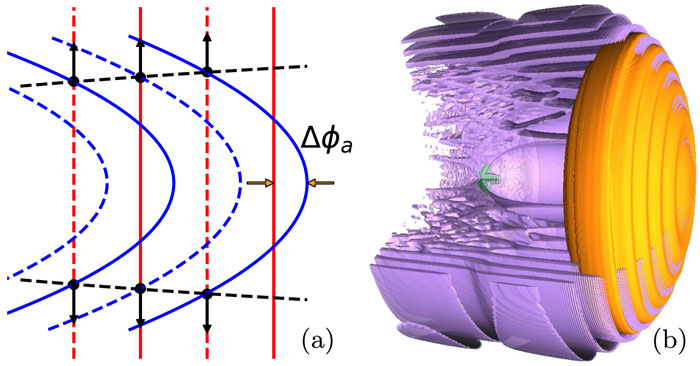
In this work, we propose a novel all-optical injection scheme that can generate high-quality electron beams with parameters beyond the above-mentioned values, by utilizing the interference of two coaxial laser pulses. In this scheme, a driver laser pulse, containing the majority of the total energy, is relatively loosely focused, with its Rayleigh range covering the injection region, while a trigger pulse, containing only a small portion of the total energy, is tightly focused shortly before the injection region, as illustrated in Fig. 1(a). Because of the different wavefront curvatures of the two lasers, interference rings are formed in the cross-section of the lasers, pinching the plasma electrons in the traps of their ponderomotive force.36 As a result, onion-like multiple subcavities are formed in the plasma wake, as shown in Fig. 1(b). With the propagation of the two lasers, the innermost subcavity expands, which slows down the effective phase velocity of the wake. Such an injection process is similar to density down-ramp injection. The one-to-one mapping between the injection phase and the initial phase greatly limits phase mixing and thus guarantees a small slice energy spread, and the defocusing force near the rear of the bubble kicks the electron trajectories from larger ellipses to smaller ones in the transverse space–momentum phase space, ensuring a small emittance of the trapped beam.37,38 The small slice energy spread is transformed to a small energy spread of the entire beam by the self-dechirping effect, which is to be discussed later. The injection length is a few hundred micrometers, which is significantly longer than those in previous all-optical injection studies, allowing large amount of beam charge.
![]()
Figure 1.Illustration of the coaxial interference of the two laser pulses (a), which creates an onion-like plasma wake (b) in the proposed injection scheme. (a) The driver laser (red lines) is relatively loosely focused and the trigger laser (blue lines) is tightly focused, with the peak wavefront illustrated by solid lines and the valley wavefront by dashed lines. Both lasers move to the right. The axial phase difference of the two lasers is Δ
Owing to its close-to-cylindrical feature, this scheme is suitable for simulation using the spectral quasicylindrical algorithm, which decomposes the Maxwell equations in k space through a Hankel–Fourier transform with only a few azimuthal modes and is more computationally efficient than a fully 3D algorithm.39 An example of a simulation using the code WarpX with the spectral quasicylindrical algorithm and the PSATD (Pseudo-Spectral Analytical Time Domain) solver40 is shown in Fig. 2. In the plots, the longitudinal coordinate is transformed to the comoving frame ζ = z − ct, where z is the longitudinal position, with its zero point at the beginning of the flattop of the plasma density profile, c is the speed of light in vacuum, and t is the time, with its zero point at the instant when the driver laser center reaches z = 0. In this simulation, the unperturbed plasma density profile has a linear up-ramp from z = −50 µm to 0 and a flattop from z = 0 to +∞, with the density of the flattop n0 = 1 × 1018 cm−3. The driver laser has a peak power of 227.13 TW and is focused at z = zf0 = 450 µm, with a focal waist of w00 = 30 µm. The trigger laser has a peak power of 1.88 TW and is focused at z = zf1 = 40 µm, with a focal waist of w01 = 2 µm. Both lasers have wavelength λ = 0.8 µm and pulse duration of 25 fs and are linearly polarized in the y direction (perpendicular to the paper), but the trigger laser is 3.75λ ahead of the driver laser. The longitudinal size of the simulation box is 65 µm, with 4096 cells, the transverse size is 500 µm, with 1024 cells, the number of azimuthal modes is 2, and the time step interval is dz/c, where dz is the longitudinal grid size. The number of macroparticles per cell is 192 in the injection region and 24 elsewhere. Owing to the interference of the two lasers, rings with ponderomotive traps are formed, creating subcavities in the plasma wake. The expansion of the innermost subcavity sharply slows down the effective phase velocity of the wakefield from t = 0.6 to 1.7 ps, as shown in Fig. 3(a), and thus injection of background plasma electrons occurs, forming a beam with ∼0.5 MeV slice energy spread. The longitudinal electric field exerts positive and negative chirping on the injected beam respectively before and after t = 18 ps, where the blowout regime is transformed to a partial-blowout regime, as shown in Figs. 3(b) and 3(c), owing to the pump-depletion effect of the driver pulse.41 The energy spread has two minima before and after the self-dechirping point, as shown in Figs. 3(d)–3(g). It can be seen that a 170 pC electron beam with energy spread no more than 0.4% and emittance no more than 0.5 mm mrad is generated. It is worth noting that the two local minima of the energy spread do not persist for other acceleration distances, owing to the non-uniform acceleration field.
![]()
Figure 2.Simulation of the proposed injection scheme. A driver laser with peak power 227.13 TW is focused to a waist of
![]()
Figure 3.Plots showing injection, self-dechirping, and beam quality. (a) Evolution of the axial longitudinal electric field
A full 3D simulation with the same grid size and parameters as above has also been performed (but only until injection has finished, owing to limited computational resources). The injected beam has a normalized emittance of 0.14 mm mrad in both transverse directions, a charge of 150 pC, and a slice energy spread of ∼0.5 MeV, which confirms the validity of the quasicylindrical simulation. This simulation at t = 1 ps is plotted in Fig. 1(b).
To explain the physics of the multisheath creation and injection, we write down the expression for the electric field of a Gaussian laser pulse in vacuum:
To investigate the influence of the initial phase difference Δϕ−∞, we vary Δz0 from 3.7 λ to 4.7 λ while keeping ΔϕCEP = 0. The theoretical evolution of the peak axial electric field Ep, obtained by adding the electric field of the two lasers using Eq. (1), is shown in Fig. 4(a) as solid lines. The simulation results are plotted as scatter points and show reasonably good agreement with theory. The injected beam charge has a strong correlation with Ep at z = 150 µm, which is a typical injection location, as shown in Fig. 4(b). Injection is suppressed if Δϕ−∞ ≈ π/2 (thus, Δϕa ≈ π with the same assumption as previously, ΔϕG ≈ π/2), because the interference is destructive on axis and the innermost subcavity does not have a clear sheath. It is worth noting that Δz0 = 3.75 λ was used for the simulation shown in Figs. 2 and 3, which maximized the injection quantity.
![]()
Figure 4.Dependence of the peak superimposed axial electric field of the two lasers
To test the influence of laser pointing jitter, we have also performed one full 3D simulation with the trigger pulse transversely offset by 2 µm, which shows that the emittance of the trapped beam in the offset direction increases to 2 mm mrad, the emittance in the vertical direction and the slice energy spread do not change significantly, and the amount of charge decreases to 115 pC. Thus, this injection scheme is robust under micrometer-scale jitter of the transverse focal position.
In summary, we have proposed a new injection scheme for laser wakefield accelerators that generates electron beams with simultaneously small energy spread, small emittance, and large amount of charge. In this scheme, one laser pulse is relatively loosely focused to drive the plasma wakefield, and another laser is tightly focused in the Rayleigh range of the former. The energy of the latter laser is only a small portion of the former, but the peak intensities are similar owing to their focal spot size difference. Within a certain range, the tightly focused laser has a convex wavefront, while the wavefront of the loosely focused laser is flat. Consequently, interference rings are formed, pinching the background electron stream and creating subcavities in the wakefield. owing to the rapidly varying wavefront curvature of the tightly focused laser, the innermost subcavity expands, slows down the effective phase velocity of the wakefield, and triggers the injection of an electron beam with a few permille energy spread and no more than 0.5 mm mrad emittance. The charge of the injected beam can be modulated by the initial phase difference of the two lasers, with the maximum exceeding 100 pC for a moderate total laser power ∼200 TW. This mechanism is sensitive to the phase difference of the two lasers, which can be either time delay or carrier envelope phase (CEP) difference. In practice, the CEP difference can be eliminated by obtaining the two laser beams by splitting one laser beam, and the time delay should be precisely controlled to maximize the injection quantity.
Acknowledgment. This work is supported by the Research Foundation of the Institute of High Energy Physics, Chinese Academy of Sciences (Grant Nos. E05153U1, E15453U2, Y9545160U2, and Y9291305U2) and the Key Research Program of Frontier Sciences of the Chinese Academy of Sciences (Grant No. QYZDJ-SSW-SLH004).
References
[1] J. M.Dawson, T.Tajima. Laser electron accelerator. Phys. Rev. Lett., 43, 267-270(1979).
[2] J. L.Collier, A. E.Dangor, E. J.Divall, P. S.Foster, J. G.Gallacher, C. J.Hooker, S. P. D.Mangles, C. D.Murphy, Z.Najmudin, A. G. R.Thomaset?al.. Monoenergetic beams of relativistic electrons from intense laser–plasma interactions. Nature, 431, 535-538(2004).
[3] F.Burgy, J.Faure, Y.Glinec, S.Gordienko, S.Kiselev, E.Lefebvre, V.Malka, A.Pukhov, J.-P.Rousseau. A laser–plasma accelerator producing monoenergetic electron beams. Nature, 431, 541-544(2004).
[4] D.Bruhwiler, J.Cary, E.Esarey, C. G. R.Geddes, W. P.Leemans, C.Nieter, C. B.Schroeder, C.Toth, J.Van Tilborg. High-quality electron beams from a laser wakefield accelerator using plasma-channel guiding. Nature, 431, 538-541(2004).
[5] J.Chen, Y.Gu, Y.He, J.Hua, D.Liu, W.Lu, Y.Ma, X.Ning, C.-H.Pai, F.Yang, Z.Yang, J.Zhang, T.Zhang. Region-of-interest micro-focus computed tomography based on an all-optical inverse Compton scattering source. Matter Radiat. Extremes, 5, 064401(2020).
[6] Y.Chen, M.Fang, K.Feng, K.Jiang, L.Ke, Y.Leng, R.Li, J.Liu, J.Liu, R.Qi, Z.Qin, C.Wang, H.Wang, W.Wang, F.Wu, Y.Xu, Z.Xu, X.Yang, C.Yu, Z.Zhang. Free-electron lasing at 27 nanometres based on a laser wakefield accelerator. Nature, 595, 516-520(2021).
[7] M.Chen, W.-Y.Liu, Z.-M.Sheng, S.-M.Weng, J.Zhang, X.-L.Zhu. Generation of single-cycle relativistic infrared pulses at wavelengths above 20
[8] C.Benedetti, S. S.Bulanov, J.Daniels, E.Esarey, C. G. R.Geddes, A. J.Gonsalves, W. P.Leemans, H.-S.Mao, D. E.Mittelberger, K.Nakamura, C. B.Schroeder, C.Tóth, J.-L.Vay. Multi-GeV electron beams from capillary-discharge-guided subpetawatt laser pulses in the self-trapping regime. Phys. Rev. Lett., 113, 245002(2014).
[9] G.Bagdasarov, C.Benedetti, J. H.Bin, N.Bobrova, S. S.Bulanov, J.Daniels, T. C. H.de Raadt, E.Esarey, L.Fan-Chiang, V.Gasilov, C. G. R.Geddes, A. J.Gonsalves, G.Korn, W. P.Leemans, K.Nakamura, C.Pieronek, P.Sasorov, C. B.Schroeder, S.Steinke, K.Swanson, C.Tóth, J.van Tilborg. Petawatt laser guiding and electron beam acceleration to 8 GeV in a laser-heated capillary discharge waveguide. Phys. Rev. Lett., 122, 084801(2019).
[10] I.Andriyash, A.D?pp, J. P.Goddet, E.Guillaume, A.Lifschitz, V.Malka, F.Massimo, K.Ta Phuoc, A.Tazfi, C.Thaury. Energy-chirp compensation in a laser wakefield accelerator. Phys. Rev. Lett., 121, 074802(2018).
[11] M.Fang, Y. X.Leng, R. X.Li, W. T.Li, J. Q.Liu, J. S.Liu, R.Qi, Z. Y.Qin, C.Wang, W. T.Wang, F. X.Wu, Y.Xu, Z. Z.Xu, C. H.Yu, Z. J.Zhang. High-brightness high-energy electron beams from a laser wakefield accelerator via energy chirp control. Phys. Rev. Lett., 117, 124801(2016).
[12] Y.Chen, K.Feng, L. T.Ke, Y. X.Leng, R. X.Li, J. S.Liu, R.Qi, Z. Y.Qin, W. T.Wang, Y.Wu, Y.Xu, Z. Z.Xu, X. J.Yang, C. H.Yu, Z. J.Zhang. Near-GeV electron beams at a few per-mille level from a laser wakefield accelerator via density-tailored plasma. Phys. Rev. Lett., 126, 214801(2021).
[13] E.Esarey, C. G. R.Geddes, A. J.Gonsalves, S. M.Hooker, W. P.Leemans, B.Nagler, K.Nakamura, C. B.Schroeder, C.Toth. GeV electron beams from a centimetre-scale accelerator. Nat. Phys., 2, 696(2006).
[14] C.Joshi, W.Lu, K. A.Marsh, S. F.Martins, W. B.Mori, A.Pak. Injection and trapping of tunnel-ionized electrons into laser-produced wakes. Phys. Rev. Lett., 104, 025003(2010).
[15] R. A.Fonseca, S. F.Martins, W. B.Mori, V. B.Pathak, L. O.Silva, J.Vieira. Magnetic control of particle injection in plasma based accelerators. Phys. Rev. Lett., 106, 225001(2011).
[16] A.Buck, M.Geissler, M.Heigoldt, S.Karsch, K.Khrennikov, F.Krausz, J. M.Mikhailova, K.Schmid, B.Shen, L.Veisz, J.Wenz, J.Xu. Shock-front injector for high-quality laser-plasma acceleration. Phys. Rev. Lett., 110, 185006(2013).
[17] E.Dodd, J. K.Kim, D.Umstadter. Laser injection of ultrashort electron pulses into wakefield plasma waves. Phys. Rev. Lett., 76, 2073-2076(1996).
[18] E.Esarey, R. F.Hubbard, W. P.Leemans, P.Sprangle, A.Ting. Electron injection into plasma wakefields by colliding laser pulses. Phys. Rev. Lett., 79, 2682-2685(1997).
[19] M.Chen, P.Norreys, Z. M.Sheng, R.Trines, W. M.Wang, J.Zhang. Mechanisms of electron injection into laser wakefields by a weak counter-propagating pulse. Eur. Phys. J.: Spec. Top., 175, 49-55(2009).
[20] J.Faure, Y.Glinec, A.Lifschitz, V.Malka, A.Norlin, C.Rechatin. Controlled injection and acceleration of electrons in plasma wakefields by colliding laser pulses. Nature, 444, 737-739(2006).
[21] A. E.Dangor, P.Foster, J. G.Gallacher, D. A.Jaroszynski, C.Kamperidis, K.Krushelnick, K. L.Lancaster, S. P. D.Mangles, C. D.Murphy, Z.Najmudin, P. A.Norreys, A. G. R.Thomas, R.Viskup. Monoenergetic electronic beam production using dual collinear laser pulses. Phys. Rev. Lett., 100, 255002(2008).
[22] S. V.Bulanov, L.-M.Chen, H.Daido, I.Daito, T. Z.Esirkepov, A.Faenov, Y.Fukuda, Y.Hayashi, T.Homma, T.Kameshima, S.Kanazawa, M.Kando, K.Kawase, H.Kiriyama, J. K.Koga, S.Kondo, H.Kotaki, J.Ma, H.Matsuura, Y.Nakai, H.Okada, T.Pikuz, A. S.Pirozhkov, H.Sasao, T.Shimomura, A.Sugiyama, M.Tanoue, D.Wakai. Electron optical injection with head-on and countercrossing colliding laser pulses. Phys. Rev. Lett., 103, 194803(2009).
[23] A.Ben-Ismail, F.Burgy, J.Faure, R.Fitour, J.Lim, V.Malka, C.Rechatin, A.Specka, A.Tafzi, H.Videau. Controlling the phase-space volume of injected electrons in a laser-plasma accelerator. Phys. Rev. Lett., 102, 164801(2009).
[24] S.Banerjee, M.Chen, S.Chen, C.Fruhling, G.Golovin, D.Haden, C.Liu, J.Luo, D.Umstadter, W.Yan, P.Zhang, B.Zhao. Electron trapping from interactions between laser-driven relativistic plasma waves. Phys. Rev. Lett., 121, 104801(2018).
[25] Q.Chen, V.Horny, S. X.Lee, D.Maslarova, D.Umstadter, J.Wang. Transient relativistic plasma grating to tailor high-power laser fields, wakefield plasma waves, and electron injection. Phys. Rev. Lett., 128, 164801(2022).
[26] X.Davoine, J.Faure, E.Lefebvre, V.Malka, C.Rechatin. Cold optical injection producing monoenergetic, multi-GeV electron bunches. Phys. Rev. Lett., 102, 065001(2009).
[27] X.Davoine, R.Lehe, A. F.Lifschitz, V.Malka, C.Thaury. Optical transverse injection in laser-plasma acceleration. Phys. Rev. Lett., 111, 085005(2013).
[28] C.-e.Chen, R.Hu, C.Lin, H.Lu, Y.Shou, X.Yan, H.Zhuo. Brilliant GeV electron beam with narrow energy spread generated by a laser plasma accelerator. Phys. Rev. Accel. Beams, 19, 091301(2016).
[29] A. M.de la Ossa, J.Osterhoff, M.Zeng. Ponderomotively assisted ionization injection in plasma wakefield accelerators. New J. Phys., 22, 123003(2020).
[30] J.Gao, D.Li, J.Wang, X.Wang, M.Zeng. Scissor-cross ionization injection in laser wakefield accelerators. Plasma Phys. Controlled Fusion, 64, 045012(2022).
[31] D. L.Bruhwiler, A.Deng, B.Hidding, D. A.Jaroszynski, O.Karger, A.Knetsch, G. G.Manahan, J. B.Rosenzweig, Z.-M.Sheng, J.Smith, G.Wittig, Y.Xi. Optical plasma torch electron bunch generation in plasma wakefield accelerators. Phys. Rev. Spec. Top.–Accel. Beams, 18, 081304(2015).
[32] C.Benedetti, M.Chen, E.Esarey, C. G. R.Geddes, W. P.Leemans, C. B.Schroeder, J.-L.Vay, L.-L.Yu. Two-color laser-ionization injection. Phys. Rev. Lett., 112, 125001(2014).
[33] D. L.Bruhwiler, B.Hidding, T.K?nigstein, G.Pretzler, J. B.Rosenzweig, D.Schiller. Ultracold electron bunch generation via plasma photocathode emission and acceleration in a beam-driven plasma blowout. Phys. Rev. Lett., 108, 035001(2012).
[34] N.Bourgeois, J.Cowley, S. M.Hooker. Two-pulse ionization injection into quasilinear laser wakefields. Phys. Rev. Lett., 111, 155004(2013).
[35] V.Horny, M.Krus, D.Maslarova, J.Psikal. Laser wakefield accelerator driven by the super-Gaussian laser beam in the focus. Plasma Phys. Controlled Fusion, 62, 024005(2020).
[36] T. M. Antonsen, P.Mora. Kinetic modeling of intense, short laser pulses propagating in tenuous plasmas. Phys. Plasmas, 4, 217-229(1997).
[37] Z.Hu, O.Kononenko, A.Martinez de la Ossa, T. J.Mehrling, J.Osterhoff, B.Sheeran, M. J. V.Streeter. Optimizing density down-ramp injection for beam-driven plasma wakefield accelerators. Phys. Rev. Accel. Beams, 20, 091301(2017).
[38] W.An, T. N.Dalichaouch, C.Joshi, F.Li, W.Lu, W. B.Mori, X. L.Xu, P.Yu. High quality electron bunch generation using a longitudinal density-tailored plasma-based accelerator in the three-dimensional blowout regime. Phys. Rev. Accel. Beams, 20, 111303(2017).
[39] I. A.Andriyash, B. B.Godfrey, M.Kirchen, R.Lehe, J.-L.Vay. A spectral, quasi-cylindrical and dispersion-free particle-in-cell algorithm. Comput. Phys. Commun., 203, 66-82(2016).
[40] A.Almgren, L. D.Amorim, J.Bell, L.Fedeli, L.Ge, K.Gott, D. P.Grote, M.Hogan, A.Huebl, R.Jambunathan, R.Lehe, A.Myers, C.Ng, M.Rowan, O.Shapoval, M.Thévenet, J.-L.Vay, H.Vincenti, E.Yang, N.Za?m, W.Zhang, Y.Zhao, E.Zoni. Modeling of a chain of three plasma accelerator stages with the WarpX electromagnetic PIC code on GPUs. Phys. Plasmas, 28, 023105(2021).
[41] R. A.Fonseca, C.Joshi, W.Lu, W. B.Mori, L. O.Silva, F. S.Tsung, M.Tzoufras, J.Vieira. Generating multi-GeV electron bunches using single stage laser wakefield acceleration in a 3D nonlinear regime. Phys. Rev. Spec. Top.–Accel. Beams, 10, 061301(2007).
[42] M.Chen, W. B.Mori, Z.-M.Sheng, M.Zeng, J.Zhang. Self-truncated ionization injection and consequent monoenergetic electron bunches in laser wakefield acceleration. Phys. Plasmas, 21, 030701(2014).


Set citation alerts for the article
Please enter your email address

© Copyright 2018-2021 | Chinese Laser Press. All Rights Reserved 沪ICP备15018463号-20