1Institute of Biomedical Optics and Optometry, Shanghai Institute for Minimally Invasive Therapy, University of Shanghai for Science and Technology, Shanghai 200093, China
2Beckman Laser Institute and Center for Biomedical Engineering, University of California, Irvine, CA 92612, USA
3Systems Engineering Institute, University of Applied Sciences Western Switzerland, Sion 1950, Switzerland
Minghui Chen, Wenyu Jia, Jintao He, Martial Geiser, Gang Zheng. A miniaturized system for measurement of the refractive index of sub-microliter liquid[J]. Chinese Optics Letters, 2019, 17(4): 041201
Copy Citation Text
This study introduced the research and development of a portable and miniaturized system for the measurement of the refractive index of sub-microliter liquid based on a microfluidic chip. A technical method of double-beam interference, was proposed for use in the measurement. Based on this, by using a laser diode as a light source, changes in the refractive index were calculated by utilizing a complementary metal–oxide–semiconductor to detect the movement of interference fringes of the liquid. Firstly, this study simulated the effects of influencing factors on the interference infringes of two Gaussian beams, such as their spot sizes, distance between two beam spots, and detection range. Secondly, this research introduced the system design and construction of the double-beam interference method and analyzed the results of refractive index tests on sub-microliter aqueous glucose solutions with different concentrations. The measurement accuracy reached 10 4 refractive index units. This system has a compact structure and is rendered portable by using batteries for its power supply. The entire system is designed to be a double Z-shaped structure with a length of about 15 cm, a width of 5 cm, and a height of about 10 cm. It can be used to measure changes in the refractive index of sub-microliter to nanoliter liquids based on the use of a microfluidic chip.
The refractive index is one of the basic physical quantities characterizing the optical properties of optically transparent materials. The variation of physical quantities, such as density, concentration, temperature, and stress on various optically transparent materials can change the refractive index[1–4]. Therefore, it is of practical significance to study methods of measuring the refractive index. The refractive index of a liquid is an important measurement parameter in industrial and agricultural production and scientific research and is an important technical means to guarantee product quality and improve product output. The measurement and control of the refractive index are widely applied in industries such as environmental monitoring, food quality, pharmacy, and disease diagnosis, and the equipment for disease diagnosis is mainly used for monitoring compositions of compounds such as glucose or carbamide. The solution to expensive imported large biochemical analyzers depends on innovation of detection technologies and research into, and development of, new scientific instruments made in China. The ideal bedside detection instrument needs to be miniaturized, easy to use, inexpensive, and with light weight. Therefore, it is necessary to research miniaturized detection instruments for use in high throughput, rapid, and accurate screening. Microfluidic chips, as a miniaturized chemical laboratory, call for a small volume of liquid and can realize detection and rapid diagnosis of macromolecules with high sensitivity and at low cost. Shi et al. made a microfluidic chip by using polydimethylsiloxane (PDMS) in 2011, which realized real-time and quantitative polymerase chain reaction (PCR) detection on cell DNA[5]. Wang et al. realized early diagnosis on specific genes of lung cancer by using a microfluidic chip in 2012[6]. Lin et al. analyzed the Ebola virus by utilizing a microfluidic chip in 2016[7]. The analysis system of microfluidic chips has good development prospects and can be applied in precision medicine.
At present, the technical systems for measuring the refractive index of minim liquid mainly include Fabrizio interferometry, Schlieren photography, a method using waveguide effects, a forward scattering method, backward scattering interferometry, sensor measurement, and pulse methods. As early as 1982, Woodruff et al.[8] measured changes in the refractive index by using Fabrizio interferometry. In the cylinder with a length of 10 cm and a diameter of 5 cm, cell flows with a central volume of 200 μL undergoing volume-layer separation were put in a Fabrizio interferometer, and interference signals were detected through a photomultiplier. To improve detection sensitivity and overcome the strict limitation of the angle of incident light, Woodruff et al.[9] improved the method based on a dual probe method. By employing Schlieren techniques, Pawliszyn et al. detected refractive index changes in a small volume of liquid[10]. By utilizing the optical fiber waveguide effects of an optical fiber sensing method to detect changes in the refractive index of liquid[11], it is found that the changes of the refractive index can result in bending and loss of light along a helical waveguide. The bending and loss increase with the decrease of bending radius or the difference in effective refractive index. Holographic detection[12] relies on transmitted fan-like light beams that produce interference in far-field and therefore generate equally spaced fringes: the changes in the refractive index lead to movement of the fringes. Bornhop et al. developed the measurement method of backward scattering interference with laser radiating parts of the channels and detected movement of fringes by using a position sensitive sensor[13,14]. In 2016, Kano et al.[15] developed a set of experimental optical systems for measuring the refractive index of a liquid based on the sensing principle of surface plasmon resonance (SPR). Basgumus et al.[16] proposed a general, stable, all-fiber sensor system for detection of the refractive index in 2016. This method relied on generation of fourfold time-division multiplexed Fresnel reflection pulses by using a nanosecond-pulse laser. Based on this, the refractive index of a liquid (or gas) is measured by detecting pulses reflected from interfaces between an optical fiber and the liquid (or air). These methods are mainly based on various interference methods[8,9,12–14,17], as well as on optical fiber waveguides[11,18] and sensor measurement[16,19].
This study introduced a miniaturized system for the measurement of the refractive index of minim liquid based on microfluidic chips. Through interference of two Gaussian beams, liquid amounts as low as sub-microliter to nanoliter could be assayed to a measurement accuracy reaching refractive index units (RIU). Furthermore, the sensitivity to concentration of glucose solutions was 100 mg/dL. The whole system was designed to be miniaturized and portable with a double Z-shaped structure with a length of about 15 cm, a width of about 5 cm, and a height of about 10 cm.
Sign up for Chinese Optics Letters TOC. Get the latest issue of Chinese Optics Letters delivered right to you!Sign up now
For the miniaturization of the instrument system, a laser diode, rather than a He–Ne laser, was used as the light source[20]. Two beams were first generated through parallel plates. One of the beams passed through the channels filled with the liquid under test, while the other was for reference purposes. The two beams converged and interfered with each other after passing through the second parallel plate and signals from interference fringes were detected through a complementary metal–oxide–semiconductor (CMOS). By measuring the movement of the interference fringes, the changes in the refractive index of the liquid were calculated.
By simulating the interference signals of the two Gaussian beams, the analytic expressions of the two Gaussian beams represented by parameter can be shown by Eqs. (1) and (2): where represents the parameter at the beam waist, and . In addition, indicates the propagation direction of the two beams, which is also the detection range; denotes the distance of the center points of the waist of the two beams in the direction; and is an integer. The interference of the two beams is demonstrated by
By substituting analytic expressions for and into Eq. (3), the following formula is obtained:
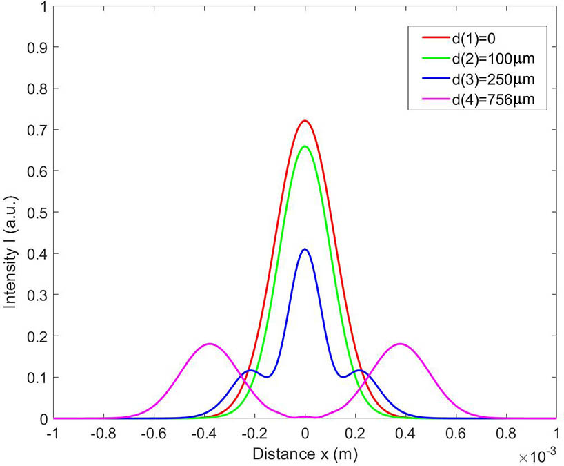
By referring to the parameters, including wavelength and beam waist of the laser diode (RLT 6715 MG), is 669.6 nm, and is 100 μm. Let equal zero. Based on this, the interference of the two beams is simulated with MATLAB™. Whether the two beams interfere with each other is related to the distance between the two beams and the detection distance , which both affect whether interference signals are generated. According to this simulation, and considering the physical size of the components, when the detection distance (from the beam waist) was 10 cm, better results were obtained. Figure 1 shows the interference intensity of the two Gaussian beams with different beam distances when was 10 cm. It can be seen that affects the interference fringes, and there is little interference for . In accordance with the measured interference intensity, and by considering the dimensions of the equipment, it was found that it was ideal that is 756 μm.
Figure 1.Interference fringes of two Gaussian beams (red, green, blue, and purple lines represent interference fringes when , , , and , respectively).
To achieve the distance between the two Gaussian beams at 756 μm and the beam waist at 100 μm, the optical parallel plate is adopted to generate the two Gaussian beams. The distance between the two Gaussian beams forming an optical parallel plate is related to the angle of incident light on the optical parallel plate, the refractive index of the glass media of the parallel plate, and the thickness of the parallel plate. Therefore, when the incident angle is designed to be 45° and the thickness of the glass of parallel plates is designed to be 1 mm, the distance between the two beams of 756 μm is obtained.
Firstly, a double-beam interferometer using a He–Ne laser as its light source was used[20]. Owing to the He–Ne laser (Melles Griot, USA) showing high coherence and a long coherence length, there was enough range of optical path difference for interference between the two beams. After the laser beams entered the first glass parallel plate at 45°, two beams with the approaching intensity were produced behind the parallel plate. The two Gaussian beams were vertically incident to the PDMS attached to the glass substrates. Gaussian beams were focused on microfluidic channels. One of the beams passed through the microfluidic channels containing liquid, and the other passed through the PDMS. After the two beams passed through the PDMS, they were incident to the second glass parallel plate at 45°. These two beams could converge and interfere with each other. The interference fringes were detected by CMOS.
Owing to the He–Ne laser being large, which is not conducive to miniaturization of the system, a laser diode was used as the light source to replace the He–Ne laser (Figs. 2 and 3 show the schematic and physical diagrams of the apparatus). The wavelength of the laser diode (RLT 6715 MG) was 669.6 nm, and the 3 dB bandwidth was 0.4 nm. The set of lenses made spots of the beams emitted from the light source, which were much smaller and were focused on the channel plane of the PDMS. The first reflective surface of parallel plate 1 changed the direction of light, making the light focus on the channel of the PDMS. The second reflective surface of parallel plate 1 makes the second beam focus on the PDMS without a channel. The focal lengths of the two lenses were 3.3 and 3.5 mm. The light source showed an optical conjugate relationship with the microfluidic channel plane. The beam spot on the microfluidic channel plane was 80 μm in diameter, and the microfluidic channel plane had a width of 250 μm and depth of 100 μm. The two glass parallel plates had the same thickness of 1 mm and were made of identical material. Therefore, the optical path difference between the two beams passing through the two parallel plates was only shown on the PDMS. The optical path difference generated when the two beams passed through the first parallel plate was compensated by the second parallel plate. Such a placement method can improve detection sensitivity. This is different from the placement method reported elsewhere[20] because the He–Ne laser has a very long coherence length, and, although the two glass plates double the optical path difference, interference fringes still appear. The coherence length of the laser diode is much smaller, so the placement method of parallel plates increases detection sensitivity. The coherence length of the laser diode[21] is where is 669.6 nm, and is 0.4 nm, which is then substituted into Eq. (5) to find that the coherence length is 493 μm. The optical path difference between the two beams is 795 μm after passing through the glass parallel plates, and then, CMOS technology can realize rapid detection at low cost and low power consumption.
Figure 2.Double-beam interferometer using a laser diode as its light source.
The concentration of human blood glucose ranges from 50 to 500 mg/dL for diabetics. By referring to measurement standards for human blood glucose, aqueous glucose solutions with different concentrations (100, 150, and 200 mg/dL) were prepared for assay. Figure 4(a) shows the interference pattern of aqueous glucose solutions with the concentration of 100 mg/dL, Fig. 4(b) shows those at 150 mg/dL, and Fig. 4(c) shows those at 200 mg/dL, respectively. The shift of the interference fringes can be observed clearly in the experiment.
Figure 4.Interference patterns of aqueous glucose solutions of different concentrations. (a) Interference pattern of aqueous glucose solutions with a concentration of 100 mg/dL. (b) Interference pattern of aqueous glucose solutions with a concentration of 150 mg/dL. (c) Interference pattern of aqueous glucose solutions with a concentration of 200 mg/dL.
By analyzing the average intensity distribution curve, the displacement of intensity distribution curves in two interference patterns can be obtained. The accuracy of displacement detection is related to the pixel in CMOS; the proposed method could obtain a detection accuracy of one tenth to one fifteenth of the wavelength. Division of the displacement by the depth (100 μm) of the PDMS with its channels showed that the change in refractive index was 0.0004. By adding a calibration curve based on the refractive index of standard pure water, the absolute refractive index can be obtained. For standard pure water, it was necessary to control the temperature of water and the ambient temperature.
In conclusion, a miniaturized system for the measurement of the refractive index of sub-microliter liquid volumes based on a microfluidic chip was investigated. For the double-beam interference method, a laser diode was used as a light source, and beams were generated and then split by passing through parallel plates. By measuring the movement of interference fringes of the beams passing through the liquid using CMOS, the changes in the refractive index of liquid were calculated. By using the system to detect the refractive index of a liquid, the measurement accuracy reached . To make the system portable and reduce its cost, the system was designed in miniature. The system, including the light source, had a length of 15 cm, a width of 5 cm, and a height of about 10 cm. The measurement of the refractive index of minim liquid based on a microfluidic chip can be applied in clinical care applications reliant on precision medicine.
Minghui Chen, Wenyu Jia, Jintao He, Martial Geiser, Gang Zheng. A miniaturized system for measurement of the refractive index of sub-microliter liquid[J]. Chinese Optics Letters, 2019, 17(4): 041201