A dual-frequency laser Doppler velocimeter implemented by a dual-polarization fiber grating laser is proposed, with the two laser frequencies produced by the two orthogonally polarized laser outputs of the fiber grating laser. The reflected laser outputs from a moving target experience the Doppler frequency shift, which is shown to be linearly related to the velocity and the beat note frequency difference between the laser outputs and the reflected light. With a digital frequency demodulation scheme, a high sensitivity of 0.64 MHz/(m/s) and a velocity resolution of less than 0.5% of the velocity for velocity measurement are demonstrated, which shows that the proposed laser Doppler velocimeter is capable of measurement of wide range of velocity.
Laser Doppler velocimeters (LDVs)[1–4] are widely employed in a number of fields, such as vibration, flow research, navigation, acoustics, and medical applications[5]. A laser reflected from a moving target experiences a Doppler frequency shift that can be detected for velocity measurement by beat between the transmitted and the reflected laser. Because the delay between the transmitted and the reflected laser converts the phase noise of the laser to intensity noise, narrow linewidth lasers are preferred for better velocity resolution, especially for those schemes with a mono-frequency laser, which may be expensive and complicated. Therefore, various schemes of LDVs based on dual-frequency lasers are proposed[6,7]. For such schemes, the frequency deviation of the dual-frequency beat note due to the Doppler effect is detected for velocity measurement. Because the beat note linewidth is much narrower than the laser linewidth, such schemes can normally result in better velocity resolution. However, because the beat note frequency is much smaller than the laser frequency, the Doppler frequency shift of the beat note is also very small, making slow motion measurement quite hard. On the other hand, the Doppler frequency shift of the beat note cannot exceed the frequency of the beat note, resulting in the upper limit for fast motion measurement. Therefore, schemes based on dual-frequency lasers should employ a larger beat frequency for measurable range expanding[8].
It then shows that LDVs benefit from lasers with a narrow linewidth and dual frequency with a large beat frequency. Fiber lasers are then excellent choices of LDV sources for their high spectral purity and light weight[9]. Among various fiber lasers, fiber grating lasers with two orthogonally polarized outputs, namely dual-polarization fiber grating lasers, are especially useful for LDV applications, which can produce beat signals after photodetection for a number of sensing applications[10]. Moreover, the beat frequency of such fiber lasers is proportional to the intracavity birefringence, which can therefore be tuned from several megahertz to tens of gigahertz. Therefore, dual-polarization fiber grating lasers are very promising for LDV applications.
In this Letter, we propose a dual-polarization fiber grating laser-based LDV. A short cavity fiber grating laser with a dual-polarization output is employed as the laser source, which is very compact and low cost. The proposed LDV shows a quite high sensitivity of 0.64 MHz/(m/s) and a good linearity. A velocity resolution of less than 0.5% of the velocity has been achieved, making the proposed LDV very promising for slow-motion measurement. Moreover, the beat note frequency of the dual-polarization fiber grating laser is 2.45 GHz and can be tuned to even higher frequencies, suggesting a very high upper limit of the measurable velocity. Therefore, the working range of the proposed dual-polarization fiber grating laser-based LDV is very wide.
Sign up for Chinese Optics Letters TOC. Get the latest issue of Chinese Optics Letters delivered right to you!Sign up now
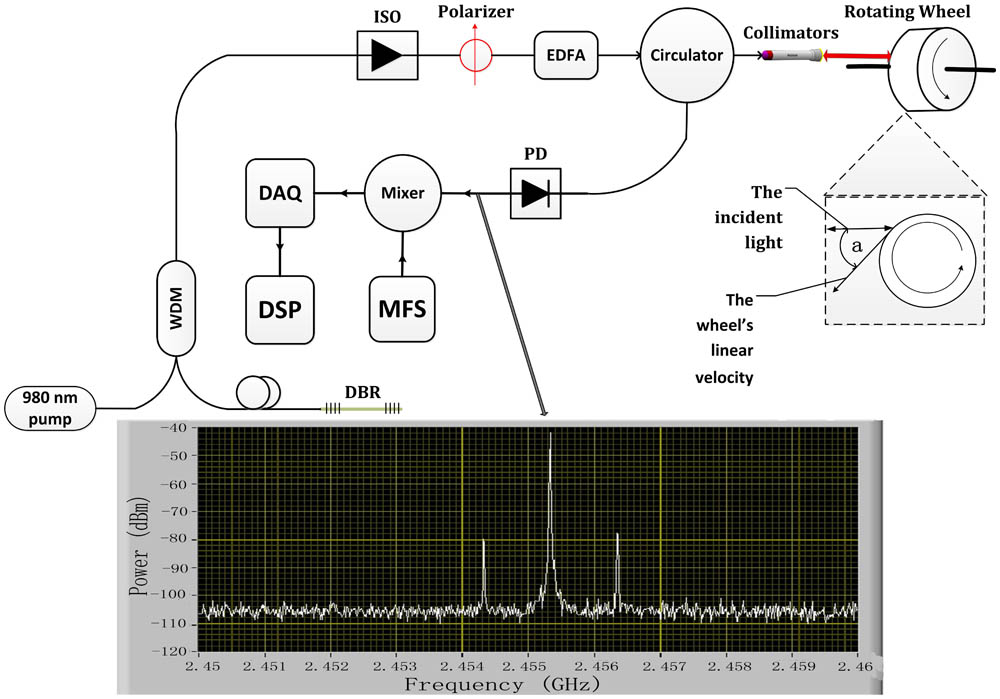
The proposed dual-polarization fiber grating laser-based LDV and the experiment setup are shown in Fig. 1. The fiber grating laser is a short cavity fiber grating laser with an output of two orthogonal polarizations. The laser output is boosted by an erbium-doped fiber amplifier (EDFA) before passing through a circulator and a collimator to point to a grinding wheel that works as a motion target. The collimator also collects the reflected laser output from the surface of the grinding wheel before directing the light through the circulator to the photodetector for measurement of the edge motion velocity of the wheel. In the experiment, a strong Fresnel reflection is present due to the collimator lens, which is guided by the circulator to the photodetector. Therefore, the Doppler frequency shift carried by the light reflected from the rotating wheel is converted to the beat frequency change by mixing the light reflected from the rotating wheel and the Fresnel reflection at the photodetector. By discriminating the beat frequency change, the velocity can then be measured.
Figure 1.Schematic diagram of the proposed LDV based on a dual-polarization fiber grating laser. ISO: isolator; WDM: wdivision multiplexer; PD: photodetector; MFS: microwave frequency synthesizer; DAQ: data acquisition; DSP: digital signal processing.
A grinding wheel with a diameter of 70 mm is used in the experiments. The maximum rotation rate of the wheel is 10000 rpm. The reflection of the wheel is enhanced by attaching a reflective strap onto the wheel, which also helps to determine the wheel rotation rate by intentionally leaving a gap on the attached reflective strap. The rotation rate can then be accurately determined by directing an amplified spontaneous emission (ASE) source to the rotating wheel. The gap results in a period of little light received for each rotation. Therefore, the rotation rate can be calculated by measuring the repetition rate of the period with little light. Figure 2 illustrates a measurement of the rotation rate 960 rpm.
Figure 2.Received waveform for the rotation rate measurement of the grinding wheel. The rotation rate of the wheel is 960 rpm.
The dual-polarization fiber grating laser is a short cavity fiber grating laser with a pair of gratings in a spacing of 5 mm. The two gratings are, respectively, 6.5 and 5.5 mm in length and are inscribed on an Er/Yb-doped fiber by an excimer of 193 nm. Pumped at 980 nm, the fiber laser operates in single longitudinal mode, which contains two orthogonal polarizations modes[11]. These two orthogonal polarization modes result from the inherent birefringence of the laser cavity. Therefore, besides the orthogonal polarizations, the frequencies of the two modes are also different, with a difference of expressed by where is the light speed in a vacuum, is the wavelength of the laser, is the average refractive index, and are the frequencies of the two polarization modes, and is the birefringence inside the laser cavity. When the two modes beat with each other at the photodetector, a beat note signal is generated with a frequency equal to . The fabricated fiber grating laser used in the experiments shows a beat note frequency of around 2.455 GHz.
Due to the Doppler effect, the two polarization modes acquire a Doppler frequency shift after being reflected from a moving target. When they mix with the Fresnel reflection on the photodetector, new beat notes result[12,13] that can be expressed by where and are the new frequencies of the two polarization modes, and are the Doppler frequency shifts of the two polarization modes of and , and and are the new beat notes. According to the Doppler effect, the Doppler frequency shift is given by where is the angle between the velocity and the laser direction, is the velocity of the moving target, and is the laser wavelength[14]. It can then be shown that because the beat frequency is about 6 orders of magnitude smaller than laser frequency. Therefore, the velocity can be written as
The inset in Fig. 1 shows the spectrum of the photodetector output for one velocity measurement. Three beat notes are received due to the mixing between the reflected light from the wheel and that from the collimator. Among the beat notes, the strongest one is due to the beating from the collimator. The two sidebands are result from the Doppler effect, and are the beat notes between the Fresnel reflections from the collimator and their Doppler frequency-shifted versions from the wheel. The Doppler frequency shifts are shown as the frequency spacings between the strongest beat note and the sidebands. By reading this Doppler frequency shift, the wheel edge velocity can then be calculated using Eq. (4).
The measured results are shown in Fig. 3. The results calculated from the measurement by the proposed LDV are shown as the triangle markers, and the calculated velocities based on the wheel rotation rate are denoted by circle markers. A quite good match between the two results is clearly identified. Moreover, the LDV shows a very good linearity and the sensitivity is about 0.64 MHz/(m/s), which is quite high compared to the beat frequency of 2.455 GHz. Furthermore, the beat frequency of 2.455 GHz also results in a high upper limit for the measurable velocity. Actually, for the proposed LDV, this upper limit comes from the electronic processing bandwidth of the demodulation system. For a modest processing bandwidth of 100 MHz, the upper limit for the measurable velocity of the proposed LDV is about 156 m/s. A wider bandwidth can expand the measurable range further.
Figure 3.Velocity versus the measured Doppler frequency shift. A fitted line for the measured results is also plotted as the solid line.
To find the velocity resolution of the proposed LDV, a demodulation system to recover the Doppler frequency shift should be implemented. As shown in Fig. 1, the output of the photodetector is downconverted through a mixer to a lower intermediate frequency (IF), which is then sampled by data acquisition. A demodulation system based on digital signal processing is then applied to the acquired data to recover the Doppler frequency shift. It can be shown that the output of the mixer containing the information of the Doppler frequency shift can be written as where is the mixer output, is the signal containing the Doppler frequency shift, and is the angular frequency of the mixer output. Therefore, the Doppler frequency shift is contained in the envelope of the mixer output. Therefore, envelope detection, such as the Hilbert transformation, is applied first to the mixer output, which results in the following signal:
Since is the signal containing the Doppler frequency shift, when the velocity changes, the Doppler frequency shift also changes. Therefore, is actually a frequency modulation signal. Following the envelope detection, a frequency demodulation algorithm should then be employed to recover the Doppler frequency shift, which in experiments is implemented through the calculation based on the phase difference between adjacent samples, where denotes the th sample, and and are the sampling interval and the frequency, respectively. Figure 4 shows one measurement of a velocity. Figure 4(a) is the acquired data of the mixer output and Fig. 4(b) is a part of its enlargement in which the envelope standing for the Doppler frequency shift is clearly identified. For the data shown in Fig. 4(a), Fig. 4(c) shows the recovered Doppler frequency shift, which is about 1.97 MHz but with some variations. The moving average over 100 samples of Fig. 4(c) is also calculated and plotted in Fig. 4(d), based on which the standard deviation can be calculated as 6 kHz. Since the sensitivity of the LDV is 0.64 MHz/(m/s), the standard deviation for the velocity measurement is then about 1 cm/s, which can be viewed as a reasonable estimation of the velocity resolution for the proposed LDV at a velocity of 3.1 m/s. It then shows that this resolution is also velocity dependent, since the moving target can induce some speckle noise to degrade the velocity resolution. This speckle noise may be more intense for faster motion. The velocity resolutions for various velocities are then measured and the results are shown in Fig. 5. It shows that the velocity resolution of the proposed LDV degrades from less than 1 to ~ 8 cm/s as the rotation velocity of the grinding wheel increases from 2 to 37 m/s. However, if we calculate the ratio between this resolution and the velocity, it then shows that this ratio becomes better for faster motion. For a velocity faster than 15 m/s, this ratio becomes stable and is basically less than 0.2%. The worse ratio may be due to the stronger vibration of the grinding wheel at a slower rotation rate, which results in an unstable rotation velocity and a larger measurement variation. For a faster rotation rate, the grinding wheel and its rotation velocity are more stable. Therefore, the ratio between the velocity resolution and the velocity becomes stable at faster motion.
Figure 4.(a) Received waveform after mixer, (b) its enlargement, (c) the recovered Doppler frequency shift, and (d) the moving average over 100 samples of (c).
In conclusion, we demonstrate a dual-polarization fiber grating laser-based Doppler velocimeter. A demodulation system based on digital signal processing to recover the Doppler frequency shift is implemented. The proposed LDV shows a high sensitivity of 0.64 MHz/(m/s), and the velocity resolution of the LDV degrades from less than 1 to 8 cm/s as the velocity of the target increases from 2 to 37 m/s. However, the ratio between the velocity resolution and the velocity is improved for faster velocities, which is basically less than 0.2%. The upper measurable velocity is basically not limited by the beat note frequency, which therefore enables measurement for very high speeds. It then shows that the proposed LDV is capable of measurement of a wide range of velocity.