
Yangshuai Li, Bingyan Wang, Panzheng Zhang, Yanli Zhang, Yanfeng Zhang, Shenlei Zhou, Weixin Ma, Jianqiang Zhu, "A novel cleanliness control method for disk amplifiers," High Power Laser Sci. Eng. 8, 04000e45 (2020)
- High Power Laser Science and Engineering
- Vol. 8, Issue 4, 04000e45 (2020)
Abstract
Keywords
1 Introduction
As the key part for energy amplification of high-power laser systems, disk amplifiers are responsible for more than 99.9% of energy amplification. Cleanliness is one of the key factors that determine the operation efficiency and life of the amplifiers. Therefore, it is especially important to achieve cleanliness control of the amplifiers[1–3]. The traditional cleanliness control method of the disk amplifiers is ‘active intake + passive exhaust’ (AIPE)[4–9]. This method uses clean air or nitrogen as a clean purge gas at a certain pressure. Owing to the particularity of the amplifier structure, it is easy to cause turbulence during the process of AIPE. As a result, the contamination floating with the airflow is difficult to exclude from the amplifier cavity. To completely realize cleanliness control, the most common method is to extend the intake and exhaust times. This method is time consuming and gas consuming. In addition, the use of high-pressure gas (one or two standard atmospheric pressures) in this method, generates certain requirements for the sealing of the amplifier cavity. Later, in order to achieve the cleanliness control of the amplifier, the method of intermittent multiple active intake and passive exhaust (IMAIPE) was developed[10], that is, the pollutant concentration was diluted by multiple and intermittent intake and exhaust. Finally, the amplifier cavity is clean. Similarly, this method of IMAIPE is also time consuming, gas consuming, and also has some problems and risks caused by high gas pressure. In order to realize the cleanliness control of the amplifier cavity at one time, based on the original cleanliness control method of AIPE, through the reasonable design of air inlets and outlets of different amplifiers, Ren et al.[11,12] realized cleanliness control with almost no turbulence. His findings also indicate that the amplifier cavity can quickly achieve cleanliness control without turbulence. However, this method also uses high-pressure gas directly in the amplifier cavity, without the secondary partial pressure of the gas chamber. The high pressure brings great danger. This method increases gas consumption and is not operable.
Therefore, how to design the flow field with low pressure and little turbulence is the key to realizing cleanliness control of the amplifier at one time. Based on the above factors, a novel cleanliness control method of active exhaust and passive intake (AEPI) is proposed in this paper. Combined with computational fluid dynamics (CFD) technology, through the optimization design of inlets and outlets, little turbulence is generated during the process of AEPI. Finally, the cleanliness control of the disk amplifier is realized at one time. At the same time, atmospheric pressure is used for intake and exhaust (tens to hundreds of Pascals below the standard atmospheric pressure), so the maximum pressure drop in the amplifier cavity is only a few thousand Pascals. Thus, the requirements for sealing the amplifier and the risk of damage to the blast shield glass are greatly reduced.
2 Control method and model verification
2.1 Introduction to AEPI and CFD technology
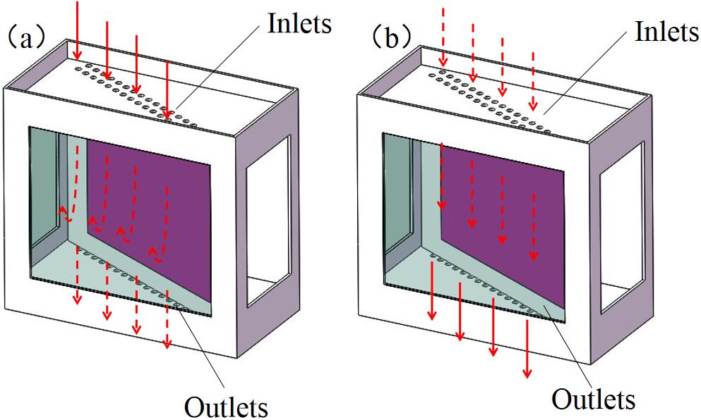
Figure 1.Cleanliness control methods: (a) AIPE; (b) AEPI.
CFD[13,14] is widely used in the numerical simulation of gas flow. First, it discretizes the hydrodynamic equations followed by the air flow in the calculation domain, transforms the strongly nonlinear partial differential equations into algebraic equations, and then uses certain numerical calculation technology to solve them, so as to obtain detailed information of the flow field distribution in the whole calculation region. Finally, the results can be visualized by computer graphics technology. Generally speaking, CFD usually includes the following steps: establishing mathematical and physical model (pre-processing), numerical algorithm solving, and result visualization (post-processing).
Sign up for High Power Laser Science and Engineering TOC. Get the latest issue of High Power Laser Science and Engineering delivered right to you!Sign up now
2.2 Numerical calculation model and governing equations
![]()
Figure 2.(a) The configuration of SSA; (b) the calculation model; (c) the mesh generation.
Similarly, to simplify the calculation model, we assumed that: (1) the thermal characteristics of the fluid are stable; (2) the flow state of the fluid is determined by the Reynolds number at the suction port speed; (3) the aerosol particles in the amplifier cavity are small enough and light enough to flow with clean gas. Therefore, the flow field can represent the distribution of aerosol particles.
The basic equations of fluid analysis and turbulent flow were used as the control equations[14]. These basic equations include the equations for the conservation of mass, momentum, and energy. The turbulent flow model is the RNG k-ε model. The default values of the software were used for the relevant parameters.
![]()
Figure 3.(a) The modified model; (b) the mesh generation of the modified model.
2.3 Numerical model verification
![]()
Figure 4.The modified SSA cavity.
The suction port is connected to a high-power fan[15] (model MF-150P), which can realize a pumping speed of 360–530 m3/h. The suction port is connected to the air chamber, which in turn is connected with outlets. When the exhaust fan starts to work, an active air extraction speed of 20–30 m/s at the outlets can be realized (20 m/s was selected in this experiment). The air inlets connected to the external atmosphere consist of a series of 10 mm diameter holes evenly distributed along the edge. A pressure gauge is placed in the modified SSA cavity to measure the internal pressure. Three smoke cakes[16] were placed near air inlets, and the smoke they produced accompanied the air into the amplifier cavity. By monitoring the fluid state of smoke in the amplifier cavity, the flow field in the amplifier is characterized, and then the pollutant removal efficiency is reflected[12]. The steady-state flow field in the amplifier cavity was recorded. The correctness of the theoretical simulation is verified by comparing the experiment with the theory.
3 Results and discussion
3.1 Theoretical simulation and experimental results
![]()
Figure 5.Pressure in the modified SSA cavity: (a) pressure of the whole cavity; (b) pressures in the positions of
![]()
Figure 6.The flow field in the modified SSA cavity in steady state: (a) contour of velocity; (b) slices of velocities in different positions; (c) vector of velocity; (d) experimental result.
Therefore, based on the above experimental and theoretical results, we believe that the CFD model is correct and the internal pressure of the amplifier cavity obtained by AEPI method is very small. To minimize turbulence, it is necessary to further optimize the SSA cavity structure and air exhaust velocity.
3.2 Design optimization
![]()
Figure 7.Vectors of different pump speeds and pressures: (a) 20 m/s; (b) 40 m/s; (c) 80 m/s; (d) 80 m/s.
![]()
Figure 8.(a) The configuration of MSA; (b) the calculation model.
![]()
Figure 9.Vectors at different air speeds in the outlets: (a) 10 m/s; (b) 20 m/s; (c) 40 m/s; (d) 80 m/s.
![]()
Figure 10.Pressures at different air speeds in the outlets: (a) 40 m/s; (b) 40 m/s; (c) 80 m/s; (d) 80 m/s.
4 Conclusion
Regarding the amplifier, a new cleanliness control method of AEPI has been proposed. Taking one type of disk amplifier as the research object, a cleanliness control model based on CFD technology has been established and verified. Based on this new cleanliness control method, optimization designs for cleanliness control in SSAs and MSAs were conducted. The research results show that it is feasible and effective to use the AEPI to achieve cleanliness control of the amplifier. The method can realize the cleanliness control of the disk amplifier by exhausting gas at one time, and also reduces the requirement of sealing the amplifier cavity. It has the advantage of time saving, gas saving, and safety and is suitable for cleanliness control of the same type of disk amplifier. It is also expected that this method could be used to realize the windowless design of the main amplification system. Of course, the flow field also involves the cooling of neodymium glass, and we will carry out this work in the next step. We also believe that there will be more efficient methods or structures for clean control of amplifiers in the future.
References
[1] Y. Li. Cleanliness control technology of high power laser systems(2015).
[2] M.-C. Jiang, J.-Q. Zhu, Z.-G. Liu, L. Wang. , , , and , Acta Photon. Sin. , ()., 45(2016).
[3] Y.-S. Li, B.-Y. Wang, P.-Z. Zhang, Z.-Y. Ren, Z.-G. Liu, S.-L. Zhou, W.-X. Ma, J. Zhu, J.-Q. Zhu, 10748(2018).
[4] I. F. Stowers, J. A. Horvath, J. A. Menapace, A. K. Burnham, S. A. Letts, 3492(1998).
[5] H.-W. Yu, W.-G. Zheng, J. Tang, C.-C. Wang, Y. Liu, S.-B. He, X.-F. Wei, X.-M. Zhang. High Power Laser Part. Beams, 13(2001).
[6] M. L. Spaeth, K. R. Manes, J. Honig. Fusion Sci. Technol, 69(2016).
[7] J. A. Paisner, W. H. Lowdermilk, J. D. Boyes, M. S. Sorem, J. M. Soures. , , , , and , Fusion Eng. Des. , ()., 44(1999).
[8] J. Honig. Opt. Eng., 43(2004).
[9] X.-F. Cheng, X.-X. Miao, Y.-B. Chen, H.-B. Wang, L. Qin, H.-B. Lu, Q. Xiong, Q. He, Z.-Q. Ma, Y.-Y. Ye, L.-B. Zhao, Y. Liu, S.-B. He, X.-D. Yuan, Q.-H. Zhu, F. Jing, W.-G. Zheng. High Power Laser Part. Beams, 24(2012).
[10] P.-Z. Zhang, T. Feng, J. Xie, Z.-Y. Ren, X.-W. Yang, L. Wang, J.-H. Li, Z.-X. Zhang, Z.-D. Cao, Z.-Q. Xia, J.-F. Hu, Z.-H. Chai, Z.-G. Liu, S.-L. Zhou, W.-X. Ma, J. Zhu. Chin. J. Lasers, 45(2018).
[11] X.-W. Yang, Z.-G. Liu, Z.-Y. Ren, H.-Q. Zhang, J.-Q. Zhu. Chin. J. Lasers, 43(2016).
[12] Z.-Y. Ren, J.-Q. Zhu, Z.-G. Liu, X.-W. Yang. High Power Laser Sci. Eng, 6(2018).
[13] Y.-S. Li, J.-Q. Zhu, X.-Y. Pang, H. Tao, X. Jiao, Y.-Z. Wu. High Power Laser Sci. Eng., 3(2015).
[14] F.-J. Wang.


Set citation alerts for the article
Please enter your email address

© Copyright 2018-2021 | Chinese Laser Press. All Rights Reserved 沪ICP备15018463号-20