• Chinese Optics Letters
  • Vol. 17, Issue 8, 080501 (2019)
Yuan Cen, Jianlan Xie, and Jianjun Liu*
Author Affiliations
  • Key Laboratory for Micro/Nano Optoelectronic Devices of Ministry of Education & Hunan Provincial Key Laboratory of Low-Dimensional Structural Physics and Devices, School of Physics and Electronics, Hunan University, Changsha 410082, China
  • show less
    DOI: 10.3788/COL201917.080501 Cite this Article Set citation alerts
    Yuan Cen, Jianlan Xie, Jianjun Liu. Multi-band imaging and focusing of photonic crystal flat lens with scatterer-size gradient[J]. Chinese Optics Letters, 2019, 17(8): 080501 Copy Citation Text show less
    Model of the PC flat lens with a scatterer-size gradient; the red arrow represents the light path of plane wave focusing, and the black arrow represents the light path of point source imaging.
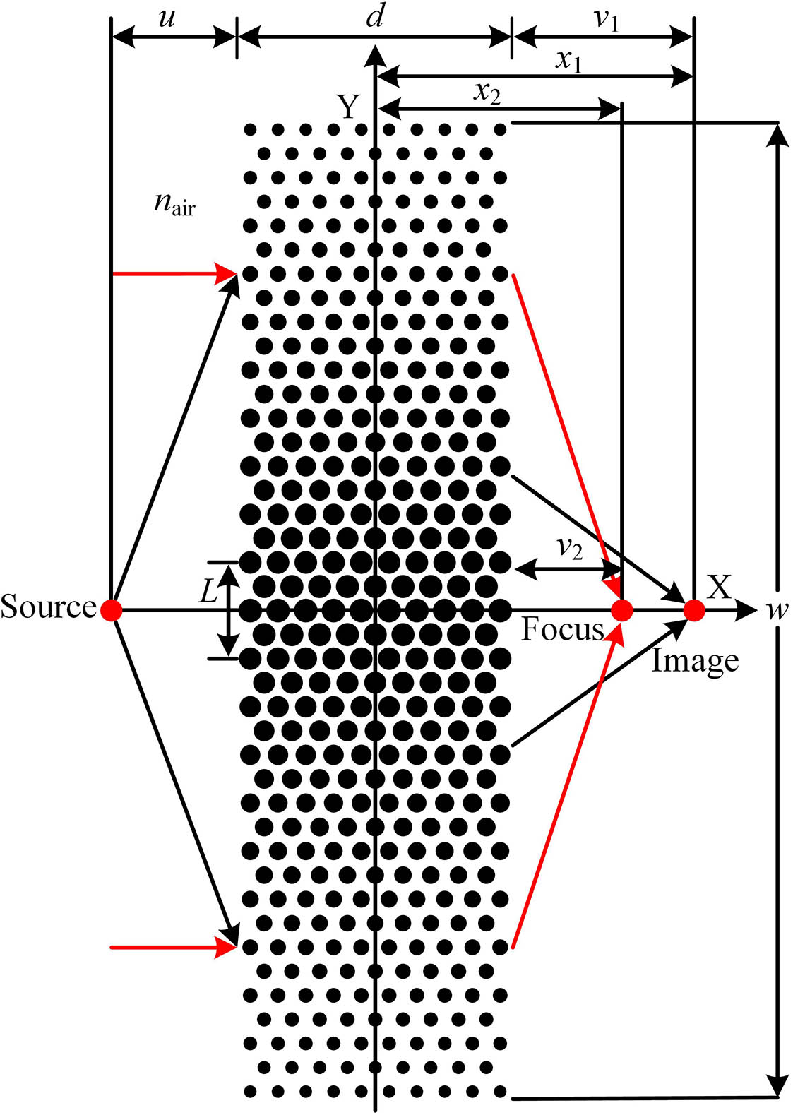
    Fig. 1. Model of the PC flat lens with a scatterer-size gradient; the red arrow represents the light path of plane wave focusing, and the black arrow represents the light path of point source imaging.
    Direction of beam propagation in the PC is analyzed by the EFL method[29]. The left picture shows the EFL of air corresponding to the frequency of the incident beam, indicating that the beam is incident on the PC from the air. The right picture shows the EFL of the band corresponding to the frequency of the refractive beam, indicating the direction of propagation of the beam in the PC[28]. This is just a schematic diagram.
    Fig. 2. Direction of beam propagation in the PC is analyzed by the EFL method[29]. The left picture shows the EFL of air corresponding to the frequency of the incident beam, indicating that the beam is incident on the PC from the air. The right picture shows the EFL of the band corresponding to the frequency of the refractive beam, indicating the direction of propagation of the beam in the PC[28]. This is just a schematic diagram.
    (a) Band structures of two CPCs with the scatterer radius r =0.40 μm and r =0.39 μm (the two radii correspond to the band structures that are, respectively, distinguished by solid and dotted lines). EM propagates along the Γ−K direction of the irreducible Brillouin zone. (b) EFLs of the first band of three CPCs with different scatterer radii, the scatterer radii of the CPC are 0.4 μm (black), 0.3 μm (red), and 0.2 μm (blue), respectively; (c) ERI of the first band of CPC with different scatterer radii; (d) influence of different scatterer radii on group velocity[31]. This is just a schematic diagram.
    Fig. 3. (a) Band structures of two CPCs with the scatterer radius r=0.40μm and r=0.39μm (the two radii correspond to the band structures that are, respectively, distinguished by solid and dotted lines). EM propagates along the ΓK direction of the irreducible Brillouin zone. (b) EFLs of the first band of three CPCs with different scatterer radii, the scatterer radii of the CPC are 0.4 μm (black), 0.3 μm (red), and 0.2 μm (blue), respectively; (c) ERI of the first band of CPC with different scatterer radii; (d) influence of different scatterer radii on group velocity[31]. This is just a schematic diagram.
    Take λ1=6.522 μm as an example: (a) the imaging field of the gradient PC flat lens when the incident beam is the point source (PS) lightwave; (b) the focusing field of the gradient PC flat lens when the incident beam is a plane wave (PW); (c) field power (normalized) of imaging of PS and focusing of PW in the axial plane; (d) field power (normalized) of imaging of PS in the imaging plane and focusing of PW in the focusing plane.
    Fig. 4. Take λ1=6.522μm as an example: (a) the imaging field of the gradient PC flat lens when the incident beam is the point source (PS) lightwave; (b) the focusing field of the gradient PC flat lens when the incident beam is a plane wave (PW); (c) field power (normalized) of imaging of PS and focusing of PW in the axial plane; (d) field power (normalized) of imaging of PS in the imaging plane and focusing of PW in the focusing plane.
    Take λ2=4.127 μm as an example: (a) the imaging field of the CPC flat lens with r=0.40 μm when the incident beam is the PS lightwave; (b) the imaging field of the gradient PC flat lens when the incident beam is the PS lightwave; (c) the focusing field of the gradient PC flat lens when the incident beam is the PW; (d) field power (normalized) of imaging of the PS and focusing of the PW in the axial plane; (e) field power (normalized) of imaging of the PS in the imaging plane and focusing of the PW in the focusing plane; (f) the second band EFLs of two CPCs with scatterer radius r=0.40 μm and r=0.39 μm (the EFLs corresponding to the two radii and the light cone are distinguished by black, purple, and blue). The blue arrow is the incident beam, which is incident from the air to the PC. The red arrow is the direction of propagation of the beam in the PC, that is, the refractive beam. This is just a schematic diagram[34].
    Fig. 5. Take λ2=4.127μm as an example: (a) the imaging field of the CPC flat lens with r=0.40μm when the incident beam is the PS lightwave; (b) the imaging field of the gradient PC flat lens when the incident beam is the PS lightwave; (c) the focusing field of the gradient PC flat lens when the incident beam is the PW; (d) field power (normalized) of imaging of the PS and focusing of the PW in the axial plane; (e) field power (normalized) of imaging of the PS in the imaging plane and focusing of the PW in the focusing plane; (f) the second band EFLs of two CPCs with scatterer radius r=0.40μm and r=0.39μm (the EFLs corresponding to the two radii and the light cone are distinguished by black, purple, and blue). The blue arrow is the incident beam, which is incident from the air to the PC. The red arrow is the direction of propagation of the beam in the PC, that is, the refractive beam. This is just a schematic diagram[34].
    Take λ5=2.582 μm as an example: (a) the imaging field of the CPC flat lens with r=0.40 μm when the incident beam is the PS lightwave; (b) the imaging field of the gradient PC flat lens when the incident beam is the PS lightwave; (c) the focusing field of the gradient PC flat lens when the incident beam is the PW; (d) field power (normalized) of imaging of the PS and focusing of the PW in the axial plane; (e) field power (normalized) of imaging of the PS in the imaging plane and focusing of the PW in the focusing plane; (f) the fifth band EFLs of two CPCs with scatterer radii r=0.40 μm and r=0.39 μm (the EFLs corresponding to the two radii and the light cone are distinguished by black, purple, and blue). The blue arrow is the incident beam, which is incident from the air to the PC. The red arrow is the direction of propagation of the beam in the PC, that is, the refractive beam. This is just a schematic diagram[34].
    Fig. 6. Take λ5=2.582μm as an example: (a) the imaging field of the CPC flat lens with r=0.40μm when the incident beam is the PS lightwave; (b) the imaging field of the gradient PC flat lens when the incident beam is the PS lightwave; (c) the focusing field of the gradient PC flat lens when the incident beam is the PW; (d) field power (normalized) of imaging of the PS and focusing of the PW in the axial plane; (e) field power (normalized) of imaging of the PS in the imaging plane and focusing of the PW in the focusing plane; (f) the fifth band EFLs of two CPCs with scatterer radii r=0.40μm and r=0.39μm (the EFLs corresponding to the two radii and the light cone are distinguished by black, purple, and blue). The blue arrow is the incident beam, which is incident from the air to the PC. The red arrow is the direction of propagation of the beam in the PC, that is, the refractive beam. This is just a schematic diagram[34].
    Effect of the thickness and width on the focal length: (a) thickness; (b) width represented by the rows of the scatterers.
    Fig. 7. Effect of the thickness and width on the focal length: (a) thickness; (b) width represented by the rows of the scatterers.
    Yuan Cen, Jianlan Xie, Jianjun Liu. Multi-band imaging and focusing of photonic crystal flat lens with scatterer-size gradient[J]. Chinese Optics Letters, 2019, 17(8): 080501
    Download Citation