
Zhi-Zhong Tan, Zhen Tan. Electrical properties of m × n cylindrical network[J]. Chinese Physics B, 2020, 29(8):
- Chinese Physics B
- Vol. 29, Issue 8, (2020)
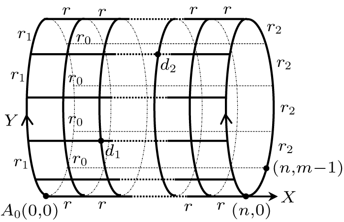
Fig. 1. Nonregular cylindrical m × n resistor network, where m and n are the numbers of resistors along the cycle and horizontal directions respectively, with unit resistors r and r 0 in the respective horizontal and loop directions except for two arbitrary boundary resistors of r 1 and r 2.
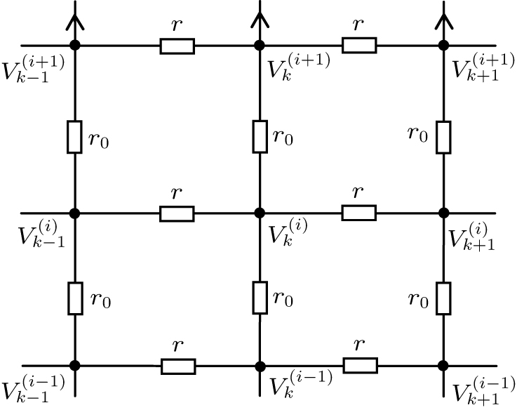
Fig. 2. Resistor sub-network with resistors and potential parameters.
Fig. 3. m × n cobweb network with arbitrary left boundary resistor of r 1.
Fig. 4. Arbitrary m × n globe network, where m and n are the number of grids along the cycle direction and horizontal direction respectively, with the resistors r and r 0 in horizontal direction and loop direction, respectively.
Fig. 5. 3D □ × n network with resistors r and r 0 in respective horizontal and vertical directions except for r 1 and r 2 on the left and right edges.
Fig. 6. 3D Δ × n network with resistors r and r 0 in the respective horizontal and vertical directions except for r 1 and r 2 on the left and right edges.
Fig. 7. 3D graph showing equivalent resistance R (A 0, Ak ) changing with h and x in Δ × n network, and resistance R (A 0, Ax ) increasing with augment of n and x , where R (A 0, A 0) = 0 when x = 0.
Fig. 8. 3D graph showing equivalent resistance R (A 0, Bk ) changing with h and x in Δ × n network, and the resistance R (A 0, Bx ) increasing with argument of n and x , where R (A 0, B 0) > 0 when x = 0.
Fig. 9. 3D graph showing equivalent resistance R (A 0, B 0) changing with h and n in Δ × n network, R (A 0, B 0) decreasing with the increase of n , and R (A 0, B 0) increasing with argument of h except for n = 0.
Fig. 10. 3D graph showing equivalent resistance R (A 0, Ak ) changing with h and x in □ × n network, and resistance R (A 0, Ax ) increasing with augment of n and x , where R (A 0, A 0) = 0 when x = 0.
Fig. 11. 3D graph showing equivalent resistance R (A 0, Ck ) changing with h and x in □ × n network, and resistance R (A 0, Cx ) incresing with augment of n and x , where R (A 0, C 0) > 0 when x = 0.
Fig. 12. Crystal lattice with resistors r and r 0 in respective horizontal and vertical directions.

Set citation alerts for the article
Please enter your email address
© Copyright 2018-2021 | Chinese Laser Press. All Rights Reserved 沪ICP备15018463号-20