• Photonics Research
  • Vol. 11, Issue 1, 55 (2023)
Xue Wen1、2, Peng Lei3, Shengxin Huang4, Xiaoyu Chen1、2, Yanchi Yuan1、2, Di Ke1、2, Rui Liu1、2, Jiaxi Liang1、2, Erqi Wang1、2, Bo Wei4、5、*, Kedi Xiong1、2、6、*, and Sihua Yang1、2、7、*
Author Affiliations
  • 1MOE Key Laboratory of Laser Life Science & Institute of Laser Life Science, South China Normal University, Guangzhou 510631, China
  • 2Guangdong Provincial Key Laboratory of Laser Life Science, College of Biophotonics, South China Normal University, Guangzhou 510631, China
  • 3Institute of Biological and Medical Engineering, Guangdong Academy of Sciences, Guangzhou 510316, China
  • 4Department of Gastrointestinal Surgery, Third Affiliated Hospital, Sun Yat-sen University, Guangzhou 510182, China
  • 5e-mail: weibo3@mail.sysu.edu.cn
  • 6e-mail: xiongkd2012@163.com
  • 7e-mail: yangsh@scnu.edu.cn
  • show less
    DOI: 10.1364/PRJ.470737 Cite this Article Set citation alerts
    Xue Wen, Peng Lei, Shengxin Huang, Xiaoyu Chen, Yanchi Yuan, Di Ke, Rui Liu, Jiaxi Liang, Erqi Wang, Bo Wei, Kedi Xiong, Sihua Yang. High-fluence relay-based disposable photoacoustic-ultrasonic endoscopy for in vivo anatomical imaging of gastrointestinal tract[J]. Photonics Research, 2023, 11(1): 55 Copy Citation Text show less

    Abstract

    Photoacoustic endomicroscopy combined with ultrasound (PAEM-US) has been a long-standing expectation for gastrointestinal tumor examination. Here, we introduce a prototype disposable PAEM-US catheter and corresponding power interface unit, featuring catheter switchability, self-internal three-dimensional scanning, and system repeatability for gastrointestinal endoscopy. By utilizing high-fluence relays, cascade insertion loss of the optical waveguide is minimized to 0.6 dB with a high performance of power resistance, and a focus-customizable acousto-optic coaxial probe is designed for high-sensitivity optical-resolution photoacoustic imaging. Imaging capability was demonstrated with in vivo anatomical imaging at 30 frames per second. Imaging results showed co-registered microscopic visualization of the microvascular and stratification of the rat colorectum with lateral resolution of 18 μm and axial resolution of 63 μm, holding great potential in the clinical detection of gastrointestinal diseases.

    1. INTRODUCTION

    Neovascularization and membrane proliferation are common signs of gastrointestinal (GI) tumor or inflammation formation [1]. Tissue biopsy is a standard procedure to reveal the histopathology of biopsy samples taken from the superficial epithelial layer. However, tumor invasion and fibrostenosis disease cannot be effectively evaluated by mucosal biopsies since they generally occur at deeper layers of the digestive wall [25]. The vascular morphology is clinically standardized for cancer staging and surgical strategy formulation by narrowband imaging combined magnification endoscopy [6,7]. Nevertheless, the optical imaging depth is limited to the superficial mucosa, and the vascular morphology in the deep mucosa has been a dead zone. Different from optical imaging methods, photoacoustic imaging (PAI) provides angiography-specific imaging with high penetration and optical resolution (OR) [817]. In the previous studies, PAI through the whole thickness of intestinal wall in animals and humans has been demonstrated [18]. PAI combined with ultrasound (US) imaging has embodied inherent advantages for clinical GI endoscopy, providing full depth of view of the membrane layer structure and microvascular angiography [1923].

    For the application of photoacoustic endomicroscopy (PAEM), two subcategories of a side-viewing PAEM catheter, distal-driven and proximal-driven, have been constantly innovated [2430]. The proximal-driven catheter is increasingly prominent and accounts for its miniaturization and low manufacturing cost. The proximal-driven catheter is driven by a scanning device to make a probe rotation and retracement inside the imaging window (IW) tube for three-dimensional (3D) imaging. Whatever that model of catheter is, to avoid cross infection and increase working efficiency, disposable imaging catheters are the workhorses in current GI examination, which is flexible and convenient in clinical settings as disposable medical consumables [31].

    A disposable imaging catheter must be catheter-switchable, self-internal 3D-scannable, and system-repeatable. In recent years, most of the PAEM catheter systems have been implemented based on mechanical scanning. Nevertheless, numerous PAEM catheters have been limited to acoustic resolution because the optical waveguides relied on large-core (>100  μm) fiber (LCF) [32]. Spatial optical coupling to the rotating small-core (10  μm) fiber (SCF) was a recently reported strategy for achieving OR-PAEM [33]. However, it seems to place an extremely high demand on mechanical matching and recalibrated optical adjustment. In addition, the studies reported usually adapted a motorized or manual pullback instead of catheter-internal retracement for 3D scanning, leading to undesirable imaging results with respiratory and motion artifacts especially in large animals. In addition, the focused beam for OR-PAI has been usually achieved by controlling the gap distance between fiber and lens [mostly a graded index (GRIN)-lens or C-lens] [3337]. Although simulation work is used for design, it is difficult to obtain repeatable and reproducible optical parameters due to the position sensitivity of the optics. In short, though mass excellent work was conducted to prove the clinical feasibility of PAEM through continuous optimization of the catheter strategy, none of previous work has referred to the disposable PAEM catheter, which exactly is the key point of the clinical translation of PAEM.

    One of the great challenges that prevent the OR-PAEM catheter from being disposable is low optical coupling efficiency and the power damage threshold of optical coupling junctions based on SCF. In order to achieve the switchable PAEM catheter, the integrated optical and electrical interface is inevitable. From the laser to the imaging catheter, there are two essential optical cold junctions in the optical path, stator to rotor, rotor to independent catheter. However, the SCF-based PAEM catheter at the wavelength of 532 nm presents considerable difficulty for optical coupling [33,35]. First, SCF with a small mode field diameter is vulnerable to laser damage with high peak power. Therefore, the flanged fiber docking leads to a high local power density, posing a threat to the end face. Second, the coupling efficiency puts extreme requirements on the concentricity and gap distance of the pair of coupling fibers, bringing much insertion loss. The low damage threshold and coupling efficiency lead to insufficient energy to excite photoacoustic signals.

    Another great challenge is the non-customized optical parameters of the imaging catheter. Working distance, depth of focus, and size of spot are vital parameters for evaluating the performance of the PAEM imaging catheter. However, with the conventional method, controlling the gap distance between the optics, it is hard to achieve an anticipant beam output with customable OR parameters. Thus, the previous approach of the distal optical strategy is empirical and unreliable for standardization.

    In this study, a prototypic disposable PAEM-US imaging catheter and a power interface unit (PIU) were first developed for GI endoscopy. A 0.25 pitch GRIN fiber (GRIN-F) was isometrically fused to an SCF, named end-cap fiber (ECF), for collimated beam output. ECF-based optical rotary connectors (ORCs) and optical pluggable connectors (OPCs) were invented, realizing high-fluence optical coupling. Based on this, the PAEM catheter can be freely combined and separated from the PIU. At the distal end of the catheter, a 2.4 mm outer diameter (OD) mini-probe was designed to be collinear with focused light and sound for high sensitivity of PAI [37,38]. In addition, a focus-fixed PAEM catheter was designed with customizable OR parameters. In this article, our engineering strategies from the catheter to PAEM-PIU were described in detail, and the in vivo imaging results were presented to demonstrate the feasibility.

    2. METHODS

    A. High-Fluence Relays for Endoscopic PAEM

    There has been a long-standing expectation that the endoscopic OR-PAEM could be compatible with OR of SCF as well as the optical coupling fluence and end-face damage threshold of LCF. In this study, ECF was first applied for OR-PAEM to overcome the challenge. An ECF was fabricated based on a 0.25 pitch GRIN-F (100/125 μm, GI2013-N, Changfei, China) and a long SCF (9/125 μm, PM-TSF-9/125, Nufern, USA) [Fig. 1(a)]. Figures 1(b) and 1(c), respectively, display the microscopic end face of the SCF and GRIN-F. Different from total reflection in the SCF, the optical waveguide in the GRIN-F presents a sinusoidal distribution due to its GRIN of fiber core. Theoretically, a point source incident beam will exhibit collimated light at 0.25 pitch length, which is preferred for optical cold coupling and beam shaping. According to the principle of optical path reversibility, a pair of ECFs can work together to form a coupling relay [Fig. 1(e)] for optical cold coupling. The prime relay consisted of the ECF, C-lens (N-SF11, Gongxin Photoelectric Technology Co., Ltd., China), and total reflection prism (H-ZF62, Jingliang Photoelectric Co., Ltd., China) [Fig. 1(f)]. Focus-fixed beam was achieved for OR-PAEM, whose depth of focus and spot size are determined by the radius of curvature of the C-lens. ECF-based optical strategy was first applied in the PAEM system [Fig. 1(d)]. A 532 nm pulsed laser (Mosquitoo X 532-2-V, InnoLas) was applied as the PAI source, and the output laser at a repetition rate of 30 kHz was spatially filtered and coupled into SCF by a fiber port coupler (PAF2-7A, Thorlabs). Subsequently, the optical waveguide went through the first rotary coupling relay (a customized ORC, Thread Photoelectric Co., Ltd., China) and the second pluggable coupling relay (a lab-built OPC). Finally, the laser was delivered to the distal end and reshaped by the prime relay. For the ORC, the optical path must be divided into the rotator and stator due to the requirement of proximal-driven mechanical scanning. For the OPC, the optical path was divided to the PIU side and catheter side, which means that the PAEM catheter can be independent of the PIU. The flange is a common device for fiber optics cold splicing, while SCF-based optical coupling introduces significant insertion loss. Worse still, the instantaneous power density at the fiber end face is too high for the small mode field of SCF, which leads to the collapse of end face. The neat facture of ECF captured many advantages. First and foremost, the power resistance has been significantly improved. Since the mode field diameter is increased tenfold, the laser damage threshold was optimized hundredfold according to the estimation formula of end laser damage threshold [39]: P=Pi×(MFD2)2×Pw,where P is the theoretical laser damage threshold, Pi is the circumference, MFD is the mode field diameter, and Pw is the estimated optical power density on air/glass interface. Posteriorly, the high coupling efficiency guaranteed sufficient energy output at the distal end for excitation of the PA signal. Finally, the position insensitive characteristics cause flexible optics for the ORC and OPC.

    ECF-based optical waveguide strategy of endoscopic PAEM system. (a) Schematic diagram and photo of ECF; 0.25 pitch (∼0.8 mm) GRIN-F was fused to SCF equidistantly for collimated light emission. (b) Fiber end-face micrograph of SCF (9/125 μm) with step refractive index n1 to n2. (c) Fiber end-face micrograph of GRIN-F (100/125 μm) with gradient refractive index n1′. (d) Schematic diagram of optical path of endoscopic PAEM system, consisting of ORC, OPC, and distal-end probe. PIU, power interface unit. (e) Coupling relay for high-fluence and power-resistant optical waveguide; (f) prime relay for fixed-focus beam scanning.

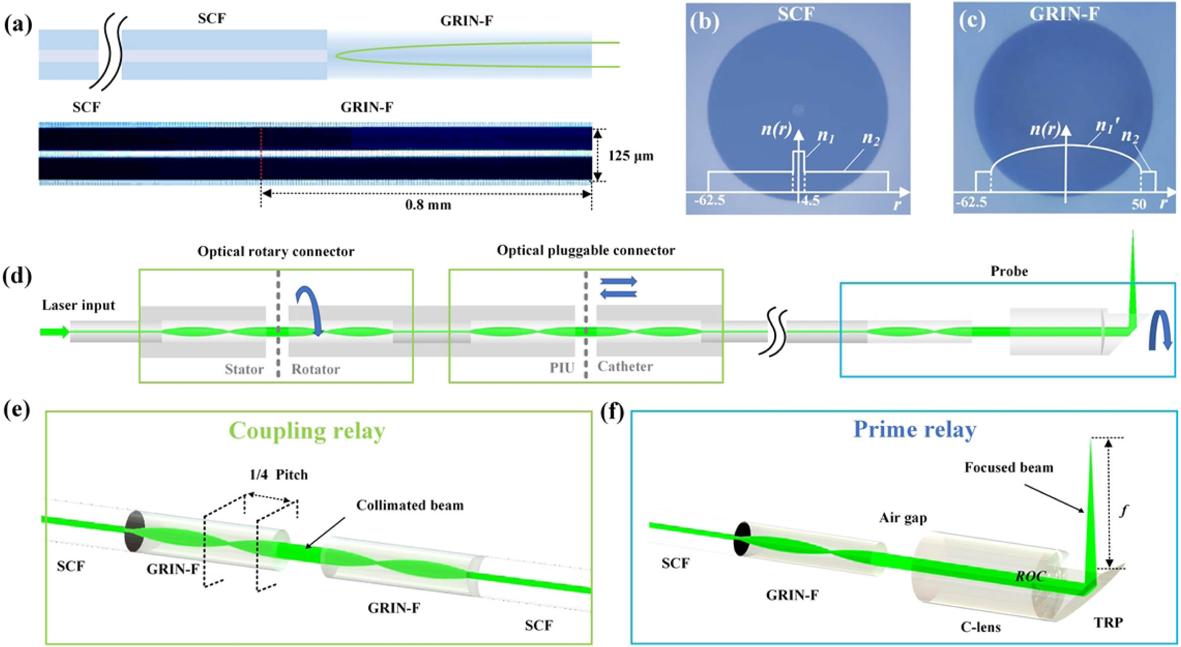
    Figure 1.ECF-based optical waveguide strategy of endoscopic PAEM system. (a) Schematic diagram and photo of ECF; 0.25 pitch (0.8  mm) GRIN-F was fused to SCF equidistantly for collimated light emission. (b) Fiber end-face micrograph of SCF (9/125 μm) with step refractive index n1 to n2. (c) Fiber end-face micrograph of GRIN-F (100/125 μm) with gradient refractive index n1. (d) Schematic diagram of optical path of endoscopic PAEM system, consisting of ORC, OPC, and distal-end probe. PIU, power interface unit. (e) Coupling relay for high-fluence and power-resistant optical waveguide; (f) prime relay for fixed-focus beam scanning.

    B. Collinear Designed PAEM-US Mini-Probe

    An important aspect of PAEM for clinical applications is that the PAEM can be combined with US for co-registered images. As vividly depicted in Fig. 2(a), the PAEM-US mini-probe performs 3D helical scanning for PA and US imaging under the video endoscope. Stratified structural morphology can be inverted by US mode, and depth-resolved angiography can be exhibited by PA mode. The miniaturized structure of light transmittance and sound reflection is applied to realize the collinearity of sound and light for optimized sensitivity [Fig. 2(b)]. The focus-fixed beam passes through the sapphire glass and illuminates biological tissue. PA and US waves are reflected by the 45° tilted sapphire glass and harvested by a front-mounted transducer. A high-frequency transducer (38.5 MHz center frequency and 60.37% bandwidth, 1YT0032, Doppler Electronic Technologies Inc.) was used for simultaneous PA and US imaging [Fig. 2(g)]. The optical and acoustic components were assembled in stainless steel (2.4 mm OD, 13 mm rigid length). A Pebax tubing (2.55 mm ID, 2.7 mm OD, Bova Plastic Co., Ltd., China) was selected for IW, protecting the cavity from being injured by insulating the high-speed-rotating probe. Polytetrafluoroethylene (PTFE) tubes were selected for the interventional catheter with 2 m length. Driven by the PIU, 1:1 torque was transformed from the proximal to distal by a torque coil (2.3 mm OD, Asahi Intecc, Japan), and the mini-probe was rotated and retraced inside the IW tube for 3D imaging. The sharp edge of a surgical blade and tungsten wire (10 μm) was imaged with PA and US, respectively. By calculating the full width at half-maximum (FWHM) of the line spread function (LSF) and point spread function (PSF), the PA lateral resolution was evaluated to be 18 μm and the US axial resolution 63 μm [Figs. 2(e) and 2(f)].

    Collinear designed PAEM-US mini-probe. (a) Schematic diagram of intra-instrument channel workable, PA, and US dual-mode imaging. (b) Schematic of PAEM-US probe with main integrated components. Inset, the section view. UT, ultrasonic transducer; TC, torque coil; S1, S2, sections 1 and 2; IW, imaging window; SG, sapphire glass; TRP, total reflection prism; SCF, single mode fiber. OC, optical channel; CC, cable channel. (c) Photograph of the fabricated PAEM-US endoscope; SUS, stainless steel. (d) Photograph of the mini-probe combined with upper electronic endoscope (2.8 mm ID channel). (e) PA lateral resolution. (f) US axial resolution. (g) Pulse response and frequency spectrum of the transducer. Fc, center frequency; BW, bandwidth.

    Figure 2.Collinear designed PAEM-US mini-probe. (a) Schematic diagram of intra-instrument channel workable, PA, and US dual-mode imaging. (b) Schematic of PAEM-US probe with main integrated components. Inset, the section view. UT, ultrasonic transducer; TC, torque coil; S1, S2, sections 1 and 2; IW, imaging window; SG, sapphire glass; TRP, total reflection prism; SCF, single mode fiber. OC, optical channel; CC, cable channel. (c) Photograph of the fabricated PAEM-US endoscope; SUS, stainless steel. (d) Photograph of the mini-probe combined with upper electronic endoscope (2.8 mm ID channel). (e) PA lateral resolution. (f) US axial resolution. (g) Pulse response and frequency spectrum of the transducer. Fc, center frequency; BW, bandwidth.

    Clinical disposable PAEM catheters must be systematically repeatable and engineerable with constant OR parameters. As illustrated in Fig. 3(a), a general method for obtaining the laser scanning beam is by controlling the intercept b between SCF and miniature lens (C-lens in this article). Variable working distance (f) and waist FWHM (w) can be acquired. However, it is extremely difficult to precisely control the intercept between SCF and focusing lenses to obtain the desired OR parameter beam. In addition, the change with the coupling medium (water as the working environment and air as the assembly environment) and wavelength will introduce aberration as a destabilizing factor. The pairing of ECF and the C-lens simplifies this concern. Since the incidence of collimated light, the f is entirely determined by the radius of curvature (planar incidence in this article) [Fig. 3(a)], referring to the following formula: f=R1n,where f is the working distance, R is the radius of curvature, and n is the refractive index of the C-lens. Another case is that the curved face of the C-lens toward fiber end face needs to consider the optical path introduced by the length (L) of the C-lens. f refers to the following new equation: f=|R1n|Ln.

    Simulation and test of prime relay. (a) Schematic of SCF-based and ECF-based optical reshaping. (b) Simulated f as a function of the rear intercept b. (c) Simulated f and waist FWHM w as a function of the radius of curvature (ROC). (d) Simulation and measurement of f as a function of b. (e) Simulation and measurement of spot size along the beam axis.

    Figure 3.Simulation and test of prime relay. (a) Schematic of SCF-based and ECF-based optical reshaping. (b) Simulated f as a function of the rear intercept b. (c) Simulated f and waist FWHM w as a function of the radius of curvature (ROC). (d) Simulation and measurement of f as a function of b. (e) Simulation and measurement of spot size along the beam axis.

    The simulated results in Fig. 3(b) indicate that, compared to SCF-based optical shaping, a constant f can be acquired in water or air (the radius of curvature was set to be 0.76). In accordance with the actual application scene, a 3.5 mm f is desired (2.3 mm in the probe and 1.2 mm outside the probe). The simulation of working distance and waist FWHM as a function of the radius of curvature is shown in Fig. 3(c) (under water environment). Finally, the 1.25 mm radius of curvature was applied for the C-lens. Figures 3(d) and 3(e) give the simulated and measured results of working distance as a function of intercept and spot size as a function of axial depth. ECF-based prime relay enjoys a constant optical-resolution beam with 3.4 mm working distance and 12.5 μm waist FWHM. Note that the intercept was no more strictly controlled for the desired beam. All the optical simulation was performed using ZEMAX OpticStudio.

    C. PAEM-PIU and Disposable PAEM-US Catheter

    PIU adapted with a disposable catheter is a standard configuration for clinical endoscopy. Figure 4 depicts the design of the PAEM-PIU and disposable PAEM-US catheter. The coupling relay was employed in the ORC and OPC for optical coupling [Fig. 4(a)]. The stator of the ORC was connected to laser. The rotator was fabricated as the F-interface, integrated with the electrical connector. The optical and electrical devices were integrated with a BNC-like housing, realizing simultaneous optical and electrical coupling by plug-in operation. The PTFE slider was driven by the retracting motor and screw rod, carrying the rotating parts to retract at 10 μm step intervals. The hollow shaft was driven by the rotating motor and synchronous wheel with a rotating speed of 30 r/s. For an optimized signal-to-noise ratio (SNR), a 50 dB low noise ring preamplifier was integrated with the rotator of electrical slip ring (H0835-06, Senring). The full view of the disposable PAEM catheter is shown in Fig. 4(b), and the side view of the PIU and catheter is shown in Fig. 4(c). The optical and electrical communication for PA and US imaging must relay on an integrated interface. Gold-plated pins were used for electronic transmission, and SC-type OPC was used for optical coupling. The optical and electrical connectors were concentrically rotated inside the retracement connector, retraced inside the shell connector together.

    Prototypic disposable PAEM-US catheter and PAEM-PIU. (a) Diagram of PAEM-PIU. F-interface, female interface; M-interface, male interface; ESR, electrical slip ring; L, Luer connector. (b) Full view of the whole PAEM catheter. (c) Connection of the catheter and PIU. Inset, caps used to house the SC-type OPC and electrical pinholes. SC, shell connector; RC, retracement connector; EC, electrical connector; OC, optical connector.

    Figure 4.Prototypic disposable PAEM-US catheter and PAEM-PIU. (a) Diagram of PAEM-PIU. F-interface, female interface; M-interface, male interface; ESR, electrical slip ring; L, Luer connector. (b) Full view of the whole PAEM catheter. (c) Connection of the catheter and PIU. Inset, caps used to house the SC-type OPC and electrical pinholes. SC, shell connector; RC, retracement connector; EC, electrical connector; OC, optical connector.

    One of the key achievements of this work is that ECF was introduced for PAEM for the first time to deliver a laser with high efficiency and stability. The low coupling efficiency and end-face damage threshold of SCF-based optical coupling bring a seemingly insurmountable challenge. Because of the high mechanical tolerance for concentric docking of 9 m core diameter, there is no high-fluence SCF-based ORC of 532 nm wavelength available. Attempts with an SCF-based ORC show an unstable and low coupling efficiency of maximum 60%. Another frustrating point is the low end-face damage threshold of SCF. After testing, the maximum permissible energy of the SCF-based cascaded optical waveguide for PAI is less than 450 nJ, which is inadequate to excite PA signal for high-SNR images. Furthermore, it is difficult to guarantee the service life due to the environmental factors (particulate matter, temperature, humidity, etc.). In contrast, the ECFs enjoyed a high coupling efficiency of over 90% and long-lasting power resistance of up to 10 μJ. Thus, the stepless variable energy can be realized for endoscopic PAEM. In this article, the in vivo experiment results were achieved under light excitation of 900  nJ/pulse, which enabled one order of magnitude of laser dose reduction compared to those implemented based on LCF [23,27]. Three groups of ORCs and OPCs were tested independently to compare the differences in ECF and SCF. The coupling rate of fiber optic junctions was defined as the ratio of output power to input power. The maximum output laser power revealed the ultimate endurance threshold of optics. The coupling efficiency and end-face damage threshold of the OPC are shown in Table 1 and the ORC in Table 2.

    Energy Coupling Efficiency and Damage Threshold of OPC

    No.SCF-BasedECF-Based
    Coupling Rate (%)Damaged (Y/N)Threshold (μJ)Coupling Rate (%)Damaged (Y/N)Threshold (μJ)
    191.4Y3.094.5N10
    291.1Y2.994.2N10.1
    390.5Y2.994.6N10.1

    Energy Coupling Efficiency and Damage Threshold of ORC

    No.SCF-BasedECF-Based
    Coupling Rate (%)Damaged (Y/N)Threshold (μJ)Coupling Rate (%)Damaged (Y/N)Threshold (μJ)
    163.4Y192N10.1
    254.1Y1.191.8N10
    357.5Y192.1N10

    ECF-based coupling relay for ORC and OPC. (a) Schematic of the output laser beam of SCF and ECF. (b) 2D spot profile of SCF and ECF at the axial distance L. Scale bar, 100 μm. (c) Spot size of ECF (Lp=0.7, 0.8, 0.9) and SCF as a function of L. (d) Coupling efficiency of ORC at different angle and rotating speed. (e) Coupling efficiency of OPC at different gap distance between two ECFs.

    Figure 5.ECF-based coupling relay for ORC and OPC. (a) Schematic of the output laser beam of SCF and ECF. (b) 2D spot profile of SCF and ECF at the axial distance L. Scale bar, 100 μm. (c) Spot size of ECF (Lp=0.7, 0.8, 0.9) and SCF as a function of L. (d) Coupling efficiency of ORC at different angle and rotating speed. (e) Coupling efficiency of OPC at different gap distance between two ECFs.

    3. IN VIVO ANATOMICAL IMAGING RESULTS

    In order to demonstrate the system’s imaging capability, the colorectum of the Sprague Dawley rat (380  g, Southern Medical University Laboratory Animal Center, China) was used for the in vivo imaging experiment. The actual working distance of our OR-PAEM catheter was customized to be 1.2 mm by prime relay. There is about 1.1 mm fixed depth of laser penetration in the tissue. The tube was relatively stationary against the intestinal wall, and the probe conducted 3D helical scanning inside the imaging tube. The self-internal 3D-scannable catheter is more reasonable, relative to the motorized-pullback catheter, since it will avoid uneven axial-retraction distortion caused by the natural curvature of the digestive tract. The range of angular view in the experiment was about 260° (6.12  mm), depending on the effective contact area. Transparent US gel was injected into the intestine to shape a cylinder and then the catheter was inserted without restraints. The coupling medium inside the Pebax tube is pure deionized water, and the gap between the tube and the intestinal wall is filled with US gel. The PA and US were collected simultaneously at a repetition frequency of 30 kHz (3.2 μs delayed trigger for US) by a high-speed data acquisition card (250 MHz sampling rate, M4i.4450-x8, Spectrum). Depth of interest of 170 points on the PA A-lines and 340 on the US was intercepted for image reconstruction. Over 2000 B-scans were achieved within 1  min at retracement speed of about 0.3 mm/s (30 fps; fps, frames per second). Visualization 1 (10 s) shows the real-time transverse view of PA and US.

    The set of 2000 PA B-scans was stacked into the 3D volume rendering image [Fig. 6(a)]. Similar to most mechanical scanning imaging, non-uniform rotational disturbances (NURDs) introduced non-rigid motion artifacts in our results. We attribute this phenomenon to the non-uniform angular velocity due to the rotational friction. The Hessian matrix was used to restore the network morphology of the blood vessels and the maximum projection (MAP) of 3D data is shown in Fig. 6(b) with 1 mm relative depth encoded. It should be noted that the depth encoded results are not accurate in the fringe area of the transverse direction. Due to the curved surface coupling, defocus and non-concentric scanning occur in the scanning range where the tissue is separated from the IW tube, causing tensile distortion of the vessels and non-uniform depth projection at the border. Every 2 PA data points were intercepted for MAP, displayed in Visualization 2 (7 s). The transverse views of PA and US were extracted from the yellow dashed line in Fig. 6(b) [Figs. 6(c) and 6(d)]. On the one hand, the OR-PAEM revealed the superficial microvascularity and deep macrovascularity at full depth of view (600  μm). On the other hand, the US imaging revealed the physiological structural stratification of the intestinal wall. The layers of Pebax, mucosa, submucosa, muscularis, and serosa can be distinguished [Fig. 6(d)]. The merged PA-US image and immunohistochemical sections demonstrated the high consistency of structural morphology [Figs. 6(e) and 6(g)]. The distribution of vessels in each membrane layer was correspondingly marked by arrows. The white arrow is suspected to be blood vessels of the external organ [Fig. 6(g)]. The image reconstructions were performed by user-defined LabVIEW (National Instruments) and MATLAB (R2020a, Math Works). The 3D volume rendering results were stacked by VolView. The depth encoded images were obtained by ImageJ (National Institutes of Health).

    In vivo imaging results of rat colorectum. (a) 3D-volume-rendered result of rat colorectum with 2 cm retracement distance. (b) MAP view with 1 mm depth encoded. (c) Transverse view of PA image. (d) Transverse view of US image. Inset, the enlarged view of yellow dashed frame. (e) Immunohistochemical staining section labeled with CD31; M, mucosa; SM, submucosa; MC, muscularis; S, serosa. (f) Merged PA and US transverse view corresponding to the yellow dashed line in (b). (g) Enlarged view of yellow dashed frame in (f).

    Figure 6.In vivo imaging results of rat colorectum. (a) 3D-volume-rendered result of rat colorectum with 2 cm retracement distance. (b) MAP view with 1 mm depth encoded. (c) Transverse view of PA image. (d) Transverse view of US image. Inset, the enlarged view of yellow dashed frame. (e) Immunohistochemical staining section labeled with CD31; M, mucosa; SM, submucosa; MC, muscularis; S, serosa. (f) Merged PA and US transverse view corresponding to the yellow dashed line in (b). (g) Enlarged view of yellow dashed frame in (f).

    To further illustrate the depth morphological characteristics, every 10 PA data points (90 points in total) were intercepted for MAP, displayed in Fig. 7(c). The primary microvessels (dense mesh-like) are distributed in the superficial mucosa. Secondary (sparse mesh-like) and tertiary vessels (branch-like) are excavated as depth increases [34]. Data analysis and statistics were displayed in Figs. 7(d) and 7(e) by Angio Tool. Combined with the results in Fig. 6(g), the vessel diameter increases with depth, while the tortuosity of secondary vessels reaches its peak near the submucosa. The density of vessels decreases with increasing depth, evaluated by counting the number of vessel junctions and calculating the porosity. Data analysis and statistics of PA angiography are expected for future differential identification of tumor vessels.

    PA depth-tomography results of rat colorectum. (a) Photograph of the rat colorectum imaging experiment. (b) Relative-depth encoded image with whole PA data. (c) Different depth of MAP view. (d) Statistics of vessel diameter and curvature as a function of depth. (e) Statistics of the number of vascular crossings and porosity as a function of depth.

    Figure 7.PA depth-tomography results of rat colorectum. (a) Photograph of the rat colorectum imaging experiment. (b) Relative-depth encoded image with whole PA data. (c) Different depth of MAP view. (d) Statistics of vessel diameter and curvature as a function of depth. (e) Statistics of the number of vascular crossings and porosity as a function of depth.

    In the in vivo experiment, the rats had fasted for two days. Anesthesia ventilator (5% isoflurane for induction and 1.5% for maintenance) was used to induce and maintain rat anesthesia. Before imaging, enema was conducted to clean the intestines followed by injection of US gel. After imaging, the rats were euthanized, and the imaged colorectum was harvested for immunohistochemical staining (CD31 antibody). South China Normal University approved all procedures used in the experiment.

    4. CONCLUSION AND DISCUSSION

    Though adherent scanning of PA combined with US was successfully demonstrated by a prototype disposable PAEM catheter, there are still fundamental limitations in this study, including NURDs bringing slight motion artifacts, manifested as lightning-like lines in the axial direction. Post-processing of the image can repair the image to some extent, but it often takes a long time to execute, which cannot be corrected online to follow the pace of real-time imaging. We have found that the rigid length and quality of probe will affect the severity of NURD artifacts. In addition, the long rigid length of the PAEM-US mini-probe is not conducive to passing through the curved part of the natural lumen. The catheter design will be further optimized by using lens fiber instead of a lens assembly process. The rigid length of the probe can be further reduced to 4  mm. The related algorithms for NURD correction will be developed in the next work.

    The mini-probe was set in a water environment by water-injected structures. It is a distressing detail that, due to the non-infiltration effect, the tiny gap often traps air bubbles by normal fluid injection, affecting the propagation path of light and sound. In addition, in the in vivo imaging, the end retained hole often enters impurities. Deformed laser beam scanning causes a low excitation efficiency and lost transverse resolution of OR-PAEM. In order to exclude these destabilizing factors for the disposable PAEM catheter, a hermetically sealed opto-sono catheter may be preferred rather than a water injection catheter.

    The angle view, depending on the effective contact area, was limited by the diameter of tube. In order to expand the angle view, shape-fixed panoramic endomicroscopy is promising for large digestive tracts by using a shaping balloon [4042]. Under this scenario, the focus-fixed beam will be customized with focus positioned on the balloon wall, and the axis of the probe will be constrained to the center of the balloon for concentric scanning. The liquid-filled balloon will brace and reshape the intestines to a circle, and 360° angle view can be achieved.

    The coupling relay maintains an excellent luminous fluence when the transmission wavelength is close to 532 nm. Benefiting from the high power-tolerance threshold, the scanning laser energy can be compensated by increasing the light source output. Thus, multispectral imaging of oxygen saturation and lymphatic vascular is feasible on the optical relays [43]. For the near-infrared wavelength (e.g., 808 nm or 1064 nm), dispersion-compensated fibers were considered to offset the positive dispersion.

    In conclusion, a prototype disposable PAEM-US catheter and a PAEM-PIU were first developed for GI endoscopy. A fixed-focus beam with 3.4 mm working distance and 12.5 μm waist FWHM was customized for OR-PAI by freely combining ECF and C-lens. ECF-based coupling relay realized a high-fluence fiber optic waveguide. A coaxial structure was employed to ensure the collinearity of the optical and acoustic focus for an optimal sensitivity. The imaging capability of the system was demonstrated with in vivo PA and US imaging of the colorectum of the rat. Imaging results depicted microvascular angiography and morphology stratification of the GI tract with PA lateral resolution of 18 μm and US axial resolution of 63 μm at a high imaging speed of 30 fps. This work sets the scene for a new optical engineering strategy of disposable PAME-US endoscopy.

    References

    [1] G. R. Lichtenstein, A. Olson, S. Travers, R. H. Diamond, D. M. Chen, M. L. Pritchard, B. G. Feagan, R. D. Cohen, B. A. Salzberg, S. B. Hanauer. Factors associated with the development of intestinal strictures or obstructions in patients with Crohn’s disease. Am. J. Gastroenterol., 101, 1030-1038(2006).

    [2] S. Kugathasan, L. A. Denson, T. D. Walters, M.-O. Kim, U. M. Marigorta, M. Schirmer, K. Mondal, C. Liu, A. Griffiths, J. D. Noe, W. V. Crandall, S. Snapper, S. Rabizadeh, J. R. Rosh, J. M. Shapiro, S. Guthery, D. R. Mack, R. Kellermayer, M. D. Kappelman, S. Steiner, D. E. Moulton, D. Keljo, S. Cohen, M. Oliva-Hemker, M. B. Heyman, A. R. Otley, S. S. Baker, J. S. Evans, B. S. Kirschner, A. S. Patel, D. Ziring, B. C. Trapnell, F. A. Sylvester, M. C. Stephens, R. N. Baldassano, J. F. Markowitz, J. Cho, R. J. Xavier, C. Huttenhower, B. J. Aronow, G. Gibson, J. S. Hyams, M. C. Dubinsky. Prediction of complicated disease course for children newly diagnosed with Crohn’s disease: a multicentre inception cohort study. Lancet, 389, 1710-1718(2017).

    [3] H. Lei, L. A. Johnson, K. A. Eaton, S. Liu, J. Ni, X. Wang, P. D. R. Higgins, G. Xu. Characterizing intestinal strictures of Crohn’s disease in vivo by endoscopic photoacoustic imaging. Biomed. Opt. Express, 10, 2542-2555(2019).

    [4] Y. Zhu, L. A. Johnson, Z. Huang, J. M. Rubin, J. Yuan, H. Lei, J. Ni, X. Wang, P. D. Higgins, G. Xu. Identifying intestinal fibrosis and inflammation by spectroscopic photoacoustic imaging: an animal study in vivo. Biomed. Opt. Express, 9, 1590-1600(2018).

    [5] H. Lei, L. A. Johnson, S. Liu, D. S. Moons, T. Ma, Q. Zhou, M. D. Rice, J. Ni, X. Wang, P. D. R. Higgins, G. Xu. Characterizing intestinal inflammation and fibrosis in Crohn’s disease by photoacoustic imaging: feasibility study. Biomed. Opt. Express, 7, 2837-2848(2016).

    [6] S. Gross, C. Trautwein, A. Behrens, R. Winograd, S. Palm, H. H. Lutz, R. Schirin-Sokhan, H. Hecker, T. Aach, J. J. Tischendorf. Computer-based classification of small colorectal polyps by using narrow-band imaging with optical magnification. Gastrointest. Endosc., 74, 1354-1359(2011).

    [7] X. G. Ni, Q. Q. Zhang, G. Q. Wang. Classification of nasopharyngeal microvessels detected by narrow band imaging endoscopy and its role in the diagnosis of nasopharyngeal carcinoma. Acta Oto-Laryngol., 137, 546-553(2017).

    [8] M. Wu, B. C. J. van Teeffelen, K. Ito, F. N. van de Vosse, R. P. A. Janssen, C. C. van Donkelaar, R. G. P. Lopata. Spectroscopic photoacoustic imaging of cartilage damage. Osteoarthrit. Cartilage, 29, 1071-1080(2021).

    [9] M. Omar, J. Aguirre, V. Ntziachristos. Optoacoustic mesoscopy for biomedicine. Nat. Biomed. Eng., 3, 354-370(2019).

    [10] M. Wu, G. Springeling, M. Lovrak, F. Mastik, S. Iskander-Rizk, T. Wang, H. M. M. van Beusekom, A. F. W. van der Steen, G. Van Soest. Real-time volumetric lipid imaging in vivo by intravascular photoacoustics at 20 frames per second. Biomed. Opt. Express, 8, 943-953(2017).

    [11] J. B. Chen, Y. C. Zhang, L. Y. He, Y. Z. Liang, L. D. Wang. Wide-field polygon-scanning photoacoustic microscopy of oxygen saturation at 1-MHz A-line rate. Photoacoustics, 20, 100195(2020).

    [12] J. B. Chen, Y. C. Zhang, X. Z. Li, J. Y. Zhu, D. F. Li, S. L. Li, C. S. Lee, L. D. Wang. Confocal visible/NIR photoacoustic microscopy of tumors with structural, functional, and nanoprobe contrasts. Photon. Res., 8, 1875-1880(2020).

    [13] C. Li, J. Shi, X. Wang, B. Wang, X. Gong, L. Song, K. K. Wong. High-energy all-fiber gain-switched thulium-doped fiber laser for volumetric photoacoustic imaging of lipids. Photon. Res., 8, 160-164(2020).

    [14] B. Cong, C. Qiu, Y. Ren, Y. Bai, M. Xing, T. Yin, X. Gong, L. Song, R. Zheng, C. Liu. A low cost sensitive transrectal photoacoustic probe with single-fiber bright-field illumination for in vivo canine prostate imaging and real-time biopsy needle guidance. IEEE Sens. J., 20, 10974-10980(2020).

    [15] R. Ansari, E. Z. Zhang, A. E. Desjardins, P. C. Beard. All-optical forward-viewing photoacoustic probe for high-resolution 3D endoscopy. Light Sci. Appl., 7, 75(2018).

    [16] J. Ma, Y. He, X. Bai, L. Sun, K. Chen, K. Oh, B. O. Guan. Flexible microbubble-based Fabry–Pérot cavity for sensitive ultrasound detection and wide-view photoacoustic imaging. Photon. Res., 8, 1558-1565(2020).

    [17] J. Pan, B. Zhang, Z. Liu, J. Zhao, Y. Feng, L. Wan, Z. Li. Microbubble resonators combined with a digital optical frequency comb for high-precision air-coupled ultrasound detectors. Photon. Res., 8, 303-310(2020).

    [18] Y. Zhu, L. A. Johnson, J. M. Rubin, H. Appelman, L. Ni, J. Yuan, X. Wang, P. D. R. Higgins, G. Xu. Strain-photoacoustic imaging as a potential tool for characterizing intestinal fibrosis. Gastroenterology, 157, 1196-1198(2019).

    [19] H. Guo, W. Qi, M. He, J. Rong, L. Xi. Co-registered photoacoustic and ultrasound imaging for tongue cancer detection. J. Innov. Opt. Health Sci., 11, 1850008(2018).

    [20] J.-M. Yang, C. Favazza, R. Chen, J. Yao, X. Cai, K. Maslov, Q. Zhou, K. K. Shung, L. V. Wang. Simultaneous functional photoacoustic and ultrasonic endoscopy of internal organs in vivo. Nat. Med., 18, 1297-1302(2012).

    [21] L. V. Wang, S. Hu. Photoacoustic tomography: in vivo imaging from organelles to organs. Science, 335, 1458-1462(2012).

    [22] L. Lin, Z. Xie, M. Xu, Y. Wang, S. Li, N. Yang, X. Gong, P. Liang, X. Zhang, L. Song, F. Cao. IVUS\IVPA hybrid intravascular molecular imaging of angiogenesis in atherosclerotic plaques via RGDfk peptide-targeted nanoprobes. Photoacoustics, 22, 100262(2021).

    [23] Y. Li, Z. Zhu, J. C. Jing, J. J. Chen, E. Heidari, Y. He, J. Zhu, T. Ma, M. Yu, Q. Zhou, Z. Chen. High-speed integrated endoscopic photoacoustic and ultrasound imaging system. IEEE J. Sel. Top. Quantum. Electron., 25, 7102005(2019).

    [24] H. Guo, C. Song, H. Xie, L. Xi. Photoacoustic endomicroscopy based on a MEMS scanning mirror. Opt. Lett., 42, 4615-4618(2017).

    [25] J.-M. Yang, K. Maslov, H. C. Yang, Q. Zhou, K. K. Shung, L. V. Wang. Photoacoustic endoscopy. Opt. Lett., 34, 1591-1593(2009).

    [26] J.-M. Yang, C. Li, R. Chen, B. Rao, J. Yao, C.-H. Yeh, A. Danielli, K. Maslov, Q. Zhou, K. K. Shung, L. V. Wang. Optical-resolution photoacoustic endomicroscopy in vivo. Biomed. Opt. Express, 6, 918-932(2015).

    [27] Z. Xie, C. Shu, D. Yang, H. Chen, C. Chen, G. Dai, K. H. Lam, J. Zhang, X. Wang, Z. Sheng, D. Gao, C. Liu, L. Song, X. Gong. In vivo intravascular photoacoustic imaging at a high speed of 100 frames per second. Biomed. Opt. Express, 11, 6721-6731(2020).

    [28] X. Bai, X. Gong, W. Hau, R. Lin, J. Zheng, C. Liu, C. Zeng, X. Zou, H. Zheng, L. Song. Intravascular optical-resolution photoacoustic tomography with a 1.1 mm diameter catheter. PLOS ONE, 9, e92463(2014).

    [29] J. Leng, J. Zhang, C. Li, C. Shu, B. Wang, R. Lin, Y. Liang, K. Wang, L. Shen, K. H. Lam, Z. Xie, X. Gong, J. Ge, L. Song. Multi-spectral intravascular photoacoustic/ultrasound/optical coherence tomography tri-modality system with a fully-integrated 0.9-mm full field-of-view catheter for plaque vulnerability imaging. Biomed. Opt. Express, 12, 1934-1946(2021).

    [30] P. Wang, T. Ma, M. N. Slipchenko, S. Liang, J. Hui, K. K. Shung, S. Roy, M. Sturek, Q. Zhou, Z. Chen, J.-X. Cheng. High-speed intravascular photoacoustic imaging of lipid-laden atherosclerotic plaque enabled by a 2-kHz barium nitrite roman laser. Sci. Rep., 4, 6889(2014).

    [31] D. Nelson. Newer technologies for endoscope disinfection: electrolyzed acid water and disposable-component endoscope systems. Gastrointest. Endosc. Clin. N. Am., 10, 319-328(2000).

    [32] Y. Li, R. Lin, C. Liu, J. Chen, H. Liu, R. Zheng, X. Gong, L. Song. In vivo photoacoustic/ultrasonic dual-modality endoscopy with a miniaturized full field-of-view catheter. J. Biophoton., 11, e201800034(2018).

    [33] M. Kim, K. W. Lee, K. S. Kim, O. Gulenko, C. Lee, B. Keum, H. J. Chun, H. S. Choi, C. U. Kim, J.-M. Yang. Intra-instrument channel workable, optical-resolution photoacoustic and ultrasonic mini-probe system for gastrointestinal endoscopy. Photoacoustics, 26, 100346(2022).

    [34] Y. Zhang, Y. Cao, J.-X. Cheng. High-resolution photoacoustic endoscope through beam self-cleaning in a graded index fiber. Opt. Lett., 44, 3841-3844(2019).

    [35] L. Wang, P. Lei, X. Wen, P. Zhang, S. Yang. Tapered fiber-based intravascular photoacoustic endoscopy for high-resolution and deep-penetration imaging of lipid-rich plaque. Opt. Express, 27, 12832-12840(2019).

    [36] X. Wen, P. Lei, K. Xiong, P. Zhang, S. Yang. High-robustness intravascular photoacoustic endoscope with a hermetically sealed opto-sono capsule. Opt. Express, 28, 19255-19269(2020).

    [37] Y. Cao, M. Alloosh, M. Sturek, J.-X. Cheng. Highly sensitive lipid detection and localization in atherosclerotic plaque with a dual-frequency intravascular photoacoustic/ultrasound catheter. Transl. Biophoton., 2, e202000004(2020).

    [38] Y. Cao, J. Hui, A. Kole, P. Wang, Q. Yu, W. Chen, M. Sturek, J.-X. Cheng. High-sensitivity intravascular photoacoustic imaging of lipid–laden plaque with a collinear catheter design. Sci. Rep., 6, 25236(2016).

    [39] https://www.thorlabschina.cn/newgrouppage9.cfm?objectgroup_id=6838&pn=FG400UEA. https://www.thorlabschina.cn/newgrouppage9.cfm?objectgroup_id=6838&pn=FG400UEA

    [40] K. Xiong, S. Yang, X. Li, D. Xing. Autofocusing optical-resolution photoacoustic endoscopy. Opt. Lett., 43, 1846-1849(2018).

    [41] K. Xiong, W. Wang, T. Guo, Z. Yuan, S. Yang. Shape-adapting panoramic photoacoustic endomicroscopy. Opt. Lett., 44, 2681-2684(2019).

    [42] Y. Zhu, L. Ni, G. Hu, L. Johnson, K. Eaton, X. Wang, P. Higgins, G. Xu. Prototype endoscopic photoacoustic-ultrasound balloon catheter for characterizing intestinal obstruction. Biomed. Opt. Express, 13, 3355-3365(2022).

    [43] C. Liu, J. Chen, Y. Zhang, J. Zhu, L. Wang. Five-wavelength optical-resolution photoacoustic microscopy of blood and lymphatic vessels. Adv. Photon., 3, 016002(2021).

    Xue Wen, Peng Lei, Shengxin Huang, Xiaoyu Chen, Yanchi Yuan, Di Ke, Rui Liu, Jiaxi Liang, Erqi Wang, Bo Wei, Kedi Xiong, Sihua Yang. High-fluence relay-based disposable photoacoustic-ultrasonic endoscopy for in vivo anatomical imaging of gastrointestinal tract[J]. Photonics Research, 2023, 11(1): 55
    Download Citation