
Jinliang Han, Jun Zhang, Xiaonan Shan, Yawei Zhang, Hangyu Peng, Li Qin, Lijun Wang, "Beam homogenization structure for a laser illuminator design based on diode laser beam combining technology," Chin. Opt. Lett. 21, 031405 (2023)
- Chinese Optics Letters
- Vol. 21, Issue 3, 031405 (2023)
Abstract
1. Introduction
In recent years, with the rapid development of laser technology, various new laser active illuminating imaging systems have been developed[1-4]. Among them, the
The traditional diode laser source realizes the circular beam and uniform beam output through fiber coupling. The irradiation angle of the output laser is the same and constant in the horizontal and vertical directions. However, the homogenization of the output laser is poor[10], which has a great influence in the illuminating application. If the illuminating beam has a lot of light and dark stripes, then the central spot is particularly strong, or the edge spot is particularly weak. In the actual imaging, it will obviously produce partially clear image, partially blurred image, or even no image phenomenon, which will have a great impact on the illuminating effect. Therefore, improving the uniformity of diode laser by beam shaping is very important for the application of laser active illuminating field[11-13]. At the same time, as a circular beam source, the illumination field of view is also round, so the field of view will be missing in the four corners, which will result in incomplete collection of information. Thus, designing a square laser source is necessary.
In this paper, a diode laser illuminating source is designed. The uniformity of laser beam is improved by beam combining and beam shaping technology, and the circular to square beam conversion is realized by a waveguide. The beam size and output divergence angle can be tunable, which is beneficial to the application of laser illuminating field.
Sign up for Chinese Optics Letters TOC. Get the latest issue of Chinese Optics Letters delivered right to you!Sign up now
2. Experimental Simulation and Design
Laser active illuminating source usually adopts air cooling. However, the line array laser and stack packing laser need to be cooled by deionized water. Hence, they are not suitable for application in this field. In this paper, a single emitter laser is used as a unit device, and typical parameters are shown in Table 1. The advantages of this scheme include the following: no influence of thermal crosstalk between unit lasers and high operation reliability. Laser output with high power and high uniformity can be obtained through beam shaping and beam combination technology[14,15]. The divergence angle in the fast axis is usually 30°–60° and the slow axis is 8°–12° because the fast and slow axis divergence angle of the diode laser is very large. Therefore, the use of the fast axis collimation lens (FAC) and slow axis collimation lens (SAC) is necessary to reduce the laser divergence angle to facilitate the subsequent spatial beam combination and polarized beam combination.
| Parameters | Unit | Specifications |
|---|---|---|
| Center wavelength | nm | 808 |
| Center wavelength tolerance | nm | |
| Output power | W | 8 |
| Operating current | A | |
| Operating voltage | V | |
| Vertical far field 95% PIB | deg | |
| Lateral far field 95% PIB | deg | |
| Emitter width | µm | 200 |
| Polarization | / | TE |
Table 1. Typical Parameters of Single Emitter Laser
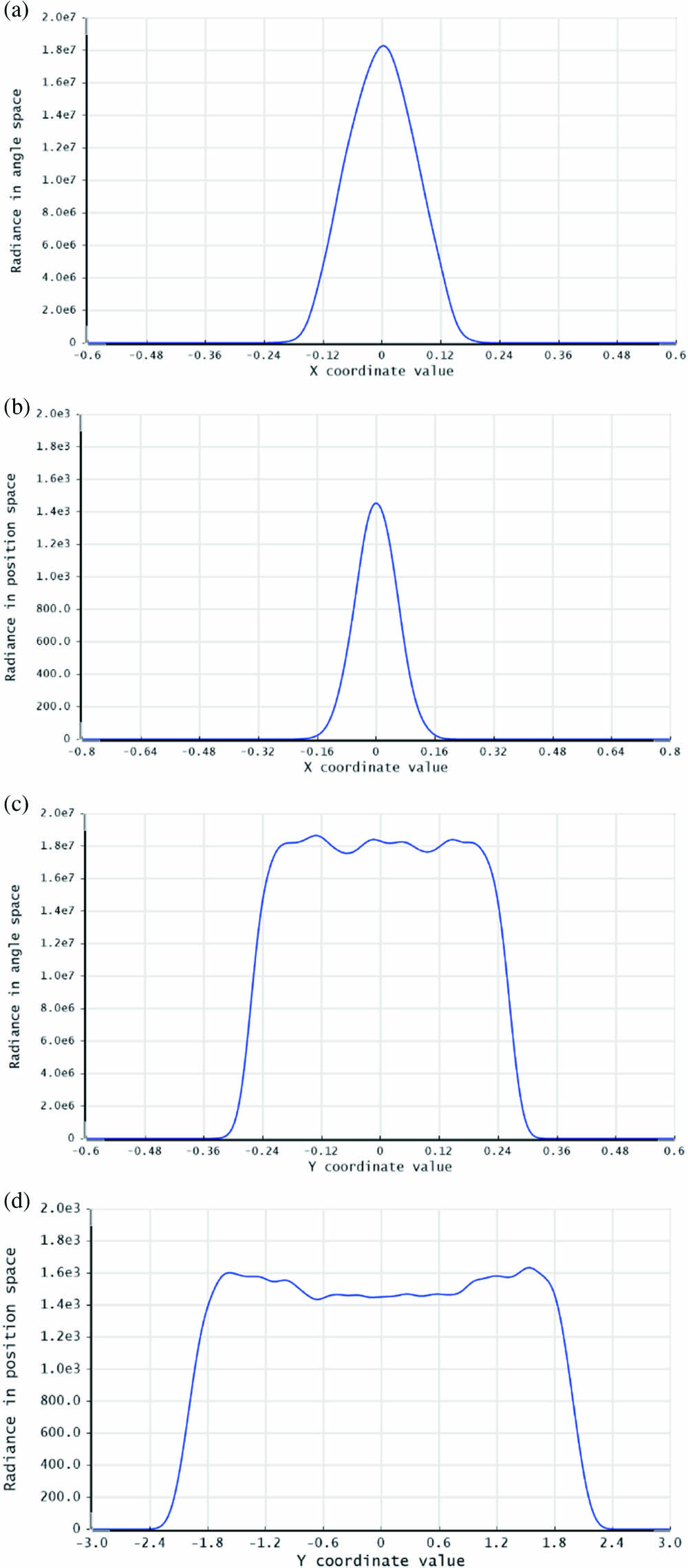
FAC adopts an aspheric column lens with a focal length of 0.3 mm, and the divergence angle in the slow axis is relatively small. Therefore, SAC adopts a spherical column lens with a focal length of 20 mm. Simulation is carried out by Zemax software, and the simulation results obtained are shown in Fig. 1. After beam shaping, the simulated divergence angle of the single emitter laser is 5.6 mrad (95%) in the fast axis and 10.5 mrad (95%) in the slow axis, and the corresponding spot size is 0.32 mm and 4.2 mm, respectively.
![]()
Figure 1.Divergence angle and beam size of single emitter laser after collimation. (a) Fast axis divergence angle; (b) fast axis beam size; (c) slow axis divergence angle; (d) slow axis beam size.
The laser parameter product (BPP) is usually used to evaluate the beam quality of diode lasers[16,17]. According to ISO-11146 standard, BPP can be expressed as
| Parameters | BPP/(mm·mrad) | ||
|---|---|---|---|
| Before collimated in fast axis | 0.0015 | 612.5 | 0.23 |
| After collimated in fast axis | 0.32 | 5.6 | 0.45 |
| Before collimated in slow axis | 0.2 | 210 | 10.5 |
| After collimated in slow axis | 4.2 | 10.5 | 11.0 |
Table 2. Beam Quality of Diode Laser before and after Collimation
Beam combination is a process of homogenizing BPP in fast and slow axes. The BPP in the slow axis is much larger than that of the fast axis, so it is necessary to make the BPP in the fast and slow axes close by stacking beams in the fast axis. To obtain high power laser output, several single emitter lasers are combined by spatial beam combination and polarized beam combination. As shown in Fig. 2, the optical path is simulated and analyzed by Zemax software. The divergence angle in the fast axis is calculated to 8 mrad when considering the installation and adjustment error. A total of 10 single emitter lasers are used as a group, and the beams are stacked in the fast axis direction through spatial combination, in which the step spacing is 0.5 mm. In the end, the beam size in the fast axis direction is 5 mm, and the BPP is 10 mm·mrad, which is close to the BPP of the slow axis laser beam. To achieve the design requirements of high power, the “half wave plate +PBS” combination method is adopted to integrate the laser beam of another 10 single emitter lasers through polarization beam combination technology, and the power density is doubled while maintaining the beam quality. The laser beam after beam combination is shown in Fig. 3(a). We use the focusing lens to couple the combined laser into the fiber with a core diameter of 200 µm and NA 0.2 to homogenize laser beam, the corresponding beam quality is about 20 mm·mrad, and the beam spot after fiber is shown in Fig. 3(b).
![]()
Figure 2.Schematic of the beam combination structure.
![]()
Figure 3.Laser beam distribution (a) after beam shaping and space combining and (b) after fiber coupling.
The diode laser through beam shaping and coupling into the optical fiber can play the role of laser uniformity, but for the illuminating source, light and dark stripes will become more obvious with the increase in transmission distance, and the beam uniformity will worsen. Therefore, a novel structure for laser beam homogenization is designed in this paper. The laser is radiated from the fiber and then passes through a waveguide to uniform the light again. In addition to uniform laser beam, the use of waveguide can also realize the conversion of circular to square beam. The length and width characteristics of the output laser can be controlled by the length and width ratio of the output port of the waveguide. Combined with the shaping lens, the irradiation angle can be changed. The schematic diagram of the optical path structure is shown in Fig. 4. In this paper, we take the uniformity of the spot and the structure size of the system into consideration. When the waveguide size is smaller, the number of laser reflection is larger, and the distribution of laser beam from waveguide is more uniform. The size of the adopted waveguide is 2 mm×8 mm×120 mm, and the output beam at 0.1 mm behind the waveguide is 2 mm×8 mm (Fig. 5).
![]()
Figure 4.Diagram of the light path structure.
![]()
Figure 5.(a) Laser beam distribution after homogenization; (b) horizontal beam size; (c) vertical beam size.
To meet the practical application, the use of the beam expanding lens is necessary to change the beam divergence angle. In this paper, the horizontal divergence angle after beam expanding is approximately 40°, the vertical divergence angle is about 10°, and the ratio is 4:1 (Fig. 6).
![]()
Figure 6.Divergence angle after beam shaping: (a) horizontal direction; (b) vertical direction.
3. Results and Discussion
In this paper, the operating current of the illuminating laser source is adjusted within the range of 0–8 A, and the P-I-V curve is shown in Fig. 7. When the operating current is 8 A and the voltage is 36.07 V, we obtain a 139.5 W power laser output. For 808 nm single emitter laser with unit output power of 8 W, 160 W laser output can be achieved after 20-channel beam combination theoretically. The output power is lower than the theoretical value after beam combination because of four reasons. (1) In the process of space beam combination, the height of the ladder is 0.5 mm, and the edge laser beam is blocked more or less in the actual installation and adjustment process. (2) The lenses in the optical path are coated with anti-reflection film, and the transmittance is 99%–99.8%, so a certain loss occurs. (3) The linear polarization degree of laser chip itself cannot reach 100% TE polarization or TM polarization, but usually is 95%–98%. In the process of polarization combination, TE polarization or TM polarization incident at an angle of 45°, compared with the ideal case incident at the Brewster angle, there is a certain angle error, so the loss will be generated. (4) Power loss will occur in the process of fiber coupling and waveguide coupling. When several processes are accumulated, the actual output power is lower than the theoretical output power.
![]()
Figure 7.P-I-V curves of laser illuminator.
The intensity distribution of the laser beam is evaluated in terms of uniformity.
Figure 8 shows the illumination laser diagram. The uniformity of the beam under different operating currents is tested experimentally, and the results are obtained. Figure 9 shows that with the increase in operating current, the laser beam uniformity maintains good stability, and a uniformity of 90.4% can be maintained, thereby guaranteeing the effect of laser illuminating.
![]()
Figure 8.Physical image of laser beam (a) horizontal direction (b) vertical direction.
![]()
Figure 9.Homogeneity of laser beam with varying operating current.
Finally, a night vision illuminating test is performed outdoors. Combined with computer image acquisition system, the beam of the diode laser output is captured by CCD. By changing the operating current, the laser power of the illuminating source is improved, and the images at 100 m are obtained (Fig. 10). CCD camera cannot detect any image information without an illuminating laser. With the increase in operating current, the image gradually becomes clearer. The illuminating beam presents a relatively regular rectangle, and the brightness within the illuminating range is very high and reaches the expected design goal.
![]()
Figure 10.Illuminating effect of diode laser with varying operating currents: (a) current 0 A; (b) current 2 A; (c) current 4 A; (d) current 6 A; (e) current 7 A; (f) current 8 A.
4. Conclusion
In this paper, an 808 nm diode laser illuminating source with an output power of 139.5 W is developed by beam shaping, spatial beam multiplexing, polarization beam multiplexing, and fiber coupling technology. The illuminating beam is homogenized by fiber coupling and waveguide, and the conversion of circular to square beam is realized. The beam uniformity under different operating currents is greater than 90%, and the feasibility of the scheme is verified by field test. The square beam output with arbitrary length and width ratio can be realized by setting the size of the waveguide, and the horizontal and vertical divergence angles can also be changed by beam expanding lens. The diode laser illuminating source and the beam homogenization system provide conditions for the application of night vision illuminating source under different conditions.
References
[1] O. Steinvall. Review of laser sensing devices and systems. Proc. SPIE, 5989, 598903(2005).
[2] L. Yang, J. Liang, W. Zhang, H. Ju, L. Ren, X. Shao. Underwater polarimetric imaging for visibility enhancement utilizing active unpolarized illumination. Opt. Commun., 438, 96(2019).
[3] X. Shan. Semiconductor laser active infrared night vision monitoring system. OME Information, 28, 5(2011).
[4] I. Baker, S. Duncanb, J. Copley. A low noise, laser-gated imaging system for long range target identification. Proc. SPIE, 5406, 133(2004).
[5] X. Wang, H. Peng, Z. Li, L. Wang. 880 nm high-power fiber-coupled diode laser module for active illumination. High Power Laser and Particle Beams, 22, 1500(2010).
[6] M. Kanskar, C. Bai, L. Bao, Z. Chen, C. Chiong, M. DeFranza, K. Fortier, M. Hemenway, S. Li, E. Martin, J. Small, B. Tomakian, W. Urbanek, B. Wilkins, J. Zhang. High brightness diodes and 600 W 62% efficient low swap fiber-coupled package. Proc. SPIE, 11262, 112620A(2020).
[7] H. An, C. Jiang, Y. Xiong, A. Inyang, Q. Zhang, A. Lewin, S. Strohmaier, G. Treusch. Advances in high power and high brightness laser bars with enhanced reliability. Proc. SPIE, 8605, 86050U(2013).
[8] M. L. Dong, J. Zhang, Y. Z. Li, P. Z. Yang, S. He, P. Li, J. J. Zhang. Study on active IR imaging with laser illumination. Infrared Technol., 28, 91(2016).
[9] L. Chen, M. Mao, X. Lin. Laser light added active near infrared image system. Semicond. Optoelectron., 35, 541(2014).
[10] F. Wang, L. Zhong, X. Tang, C. Xu, C. Wan. A homogeneous focusing system for diode lasers and its applications in metal surface modification. Opt. Laser Technol., 102, 197(2018).
[11] S. Heinemann, H. Fritsche, B. Kruschke, T. Schmidt, W. Gries. Compact high brightness diode laser emitting 500 W from a 100 µm fiber. Proc. SPIE, 8605, 86050Q(2013).
[12] Z. Liu, H. Liu, Z. Lu, Q. Li, J. Li. A beam homogenizer for digital micromirror device lithography system based on random freeform microlenses. Opt. Commun., 443, 211(2019).
[13] H. Zhao. Research on smoothing technology of laser illumination system. J. Changchun Univ. Sci. Technol., 40, 14(2017).
[14] D. Xu, D. Ma, Z. Yu, L. Xu, X. Chen. Kilowatt wavelength stabilized CW and QCW diode laser. Proc. SPIE, 11262, 112620C(2020).
[15] L. Han, M. Hao. Direct combining output of fiber coupled laser diodes via fiber combiner with high efficiency and multiple input ports. Optik, 218, 165268(2020).
[16] Z. Wang, A. Segref, T. Koenning, R. Pandey. Fiber coupled diode laser beam parameter product calculation and rules for optimized design. Proc. SPIE, 7918, 791809(2011).
[17] H. Yu, X. Ma, Y. Zou, L. Jin, Y. Xu, L. Xu, H. Zhang. Beam shaping design for fiber-coupled laser-diode system based on a building block trapezoid prism. Opt. Laser Technol., 109, 366(2019).
[18] H. Zhua, X. Fua, S. Fan, L. Liang, X. Lin, Y. Ning. The conversion from a Gaussian-like beam to a flat-top beam in the laser hardening processing using a fiber coupled diode laser source. Opt. Laser Technol., 125, 106028(2020).


Set citation alerts for the article
Please enter your email address

© Copyright 2018-2021 | Chinese Laser Press. All Rights Reserved 沪ICP备15018463号-20