• Photonics Research
  • Vol. 6, Issue 5, B6 (2018)
Davide Rocco1、*, Valerio F. Gili2, Lavinia Ghirardini3, Luca Carletti1, Ivan Favero2, Andrea Locatelli1、4, Giuseppe Marino2、5, Dragomir N. Neshev5, Michele Celebrano3, Marco Finazzi3, Giuseppe Leo2, and Costantino De Angelis1、4
Author Affiliations
  • 1Department of Information Engineering, University of Brescia, Via Branze 38, Brescia 25123, Italy
  • 2Matériaux et Phénomènes Quantiques, Université Paris Diderot, CNRS UMR 7162, 10 rue A. Domon et L. Duquet, 75013 Paris, France
  • 3Department of Physics, Politecnico di Milano, Piazza Leonardo Da Vinci 32, Milano 20133, Italy
  • 4National Institute of Optics (INO), Via Branze 45, Brescia 25123, Italy
  • 5Nonlinear Physics Centre, Research School of Physics and Engineering, The Australian National University, Canberra, ACT 2601, Australia
  • show less
    DOI: 10.1364/PRJ.6.0000B6 Cite this Article Set citation alerts
    Davide Rocco, Valerio F. Gili, Lavinia Ghirardini, Luca Carletti, Ivan Favero, Andrea Locatelli, Giuseppe Marino, Dragomir N. Neshev, Michele Celebrano, Marco Finazzi, Giuseppe Leo, Costantino De Angelis. Tuning the second-harmonic generation in AlGaAs nanodimers via non-radiative state optimization [Invited][J]. Photonics Research, 2018, 6(5): B6 Copy Citation Text show less
    (a) Extinction efficiency of the isolated cylinder versus the radius of its section: the continuous (dashed) line refers to modeling (experimental data); (b) extinction efficiency decomposed in electric dipole p, magnetic dipole m, toroidal dipole t, electric quadrupole Qe, and magnetic quadrupole Qm contributions. (c) Electric field enhancement for a nanocylinder with radius 320 nm. The white arrows indicate the electric field vector (in-plane components). (d) Magnitude of the volume integral of the normalized nonlinear current density ρSHG inside the cylinder as a function of the radius.
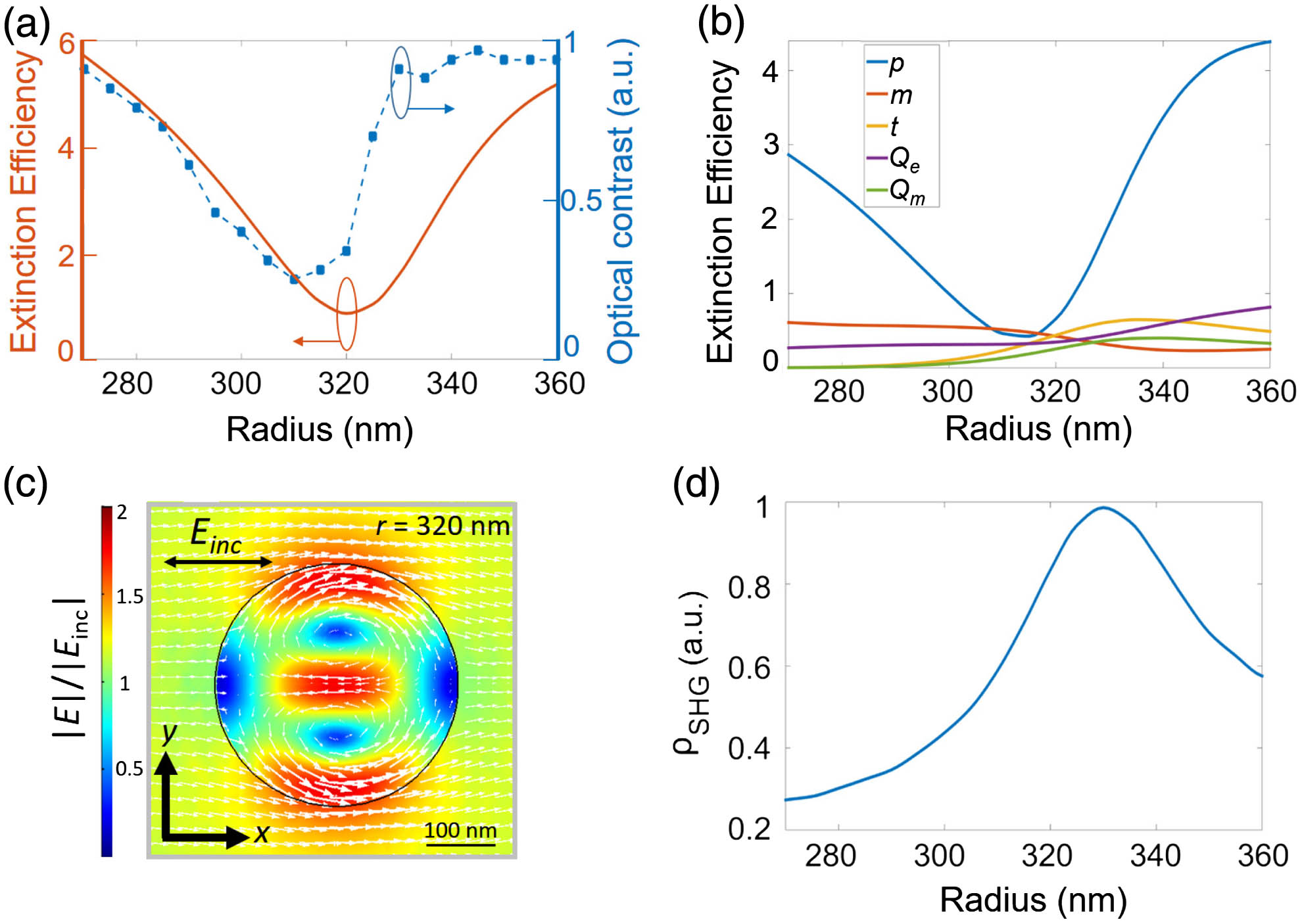
    Fig. 1. (a) Extinction efficiency of the isolated cylinder versus the radius of its section: the continuous (dashed) line refers to modeling (experimental data); (b) extinction efficiency decomposed in electric dipole p, magnetic dipole m, toroidal dipole t, electric quadrupole Qe, and magnetic quadrupole Qm contributions. (c) Electric field enhancement for a nanocylinder with radius 320 nm. The white arrows indicate the electric field vector (in-plane components). (d) Magnitude of the volume integral of the normalized nonlinear current density ρSHG inside the cylinder as a function of the radius.
    AlGaAs-on-AlOx nanodimers. (a) SEM image of a part of the array. The principal axis of the dimer is oriented parallel to the [100] direction of the AlGaAs crystal. (b) Pictorial view of the proposed structure. Calculated Cartesian decomposition of the dimer photonic modes in the case of light linearly polarized either along (c) the x axis or (d) the y axis for different dimer radii at λ=1550 nm. (e) Phase difference between p and t multipoles in the case of incident light polarized along the x (blue curve) or the y axis (red curve). A black dashed line corresponding to −π is plotted as a reference.
    Fig. 2. AlGaAs-on-AlOx nanodimers. (a) SEM image of a part of the array. The principal axis of the dimer is oriented parallel to the [100] direction of the AlGaAs crystal. (b) Pictorial view of the proposed structure. Calculated Cartesian decomposition of the dimer photonic modes in the case of light linearly polarized either along (c) the x axis or (d) the y axis for different dimer radii at λ=1550  nm. (e) Phase difference between p and t multipoles in the case of incident light polarized along the x (blue curve) or the y axis (red curve). A black dashed line corresponding to π is plotted as a reference.
    (a) Electric–magnetic field distribution in the x–y plane at the fundamental wavelength in the dimer structure for the two incident (inc) polarizations, as indicated by the white arrows: for a dimer with (a), (d) a radius of 335 nm and (b), (e) with a radius of 320 nm; in (a) and (b) the height is 200 nm; in (d) and (e) it is 300 nm. (c) Schematic description of the coupling mechanism in the dimer for the two orthogonal incident polarizations: p indicates the electric dipole, t is the toroidal dipole, and M is the magnetic field loop. (f) Electric and magnetic field enhancement as a function of the dimer radius for the x (blue curve) and y (orange curve) incident polarizations.
    Fig. 3. (a) Electric–magnetic field distribution in the xy plane at the fundamental wavelength in the dimer structure for the two incident (inc) polarizations, as indicated by the white arrows: for a dimer with (a), (d) a radius of 335 nm and (b), (e) with a radius of 320 nm; in (a) and (b) the height is 200 nm; in (d) and (e) it is 300 nm. (c) Schematic description of the coupling mechanism in the dimer for the two orthogonal incident polarizations: p indicates the electric dipole, t is the toroidal dipole, and M is the magnetic field loop. (f) Electric and magnetic field enhancement as a function of the dimer radius for the x (blue curve) and y (orange curve) incident polarizations.
    (a) Numerical calculations of the SH efficiency for x-polarized pump beam (blue line) and y-polarized pump beam (red line) as a function of cylinder radius with respect to the SHG of the single cylinder (black line). (b) Measured SHG for the dimer structure as a function of radius for two pump polarizations: along the x axis (blue curve) and along the y axis (red curve). The black line represents the measured SHG for the single cylinder structure. (c) Calculated volume integral of the nonlinear polarization in the isolated cylinder (black line) and in the dimer for x- (blue line) and y- (red line) polarized pump beams.
    Fig. 4. (a) Numerical calculations of the SH efficiency for x-polarized pump beam (blue line) and y-polarized pump beam (red line) as a function of cylinder radius with respect to the SHG of the single cylinder (black line). (b) Measured SHG for the dimer structure as a function of radius for two pump polarizations: along the x axis (blue curve) and along the y axis (red curve). The black line represents the measured SHG for the single cylinder structure. (c) Calculated volume integral of the nonlinear polarization in the isolated cylinder (black line) and in the dimer for x- (blue line) and y- (red line) polarized pump beams.
    Simulated (top) and experimentally obtained (bottom) SH emission patterns decomposed in co-polarized and cross-polarized (with respect to the pump beam) contributions for the dimer structure with r=335 nm [(a) x-polarized pump] and with r=320 nm [(b) y-polarized pump].
    Fig. 5. Simulated (top) and experimentally obtained (bottom) SH emission patterns decomposed in co-polarized and cross-polarized (with respect to the pump beam) contributions for the dimer structure with r=335  nm [(a) x-polarized pump] and with r=320  nm [(b) y-polarized pump].
    Davide Rocco, Valerio F. Gili, Lavinia Ghirardini, Luca Carletti, Ivan Favero, Andrea Locatelli, Giuseppe Marino, Dragomir N. Neshev, Michele Celebrano, Marco Finazzi, Giuseppe Leo, Costantino De Angelis. Tuning the second-harmonic generation in AlGaAs nanodimers via non-radiative state optimization [Invited][J]. Photonics Research, 2018, 6(5): B6
    Download Citation