
Yaya Zhang, Jie Zhao, Dayong Wang, Yunxin Wang, Lu Rong, "Lensless Fourier-transform terahertz digital holography for real-time full-field phase imaging," Photonics Res. 10, 323 (2022)
- Photonics Research
- Vol. 10, Issue 2, 323 (2022)
Abstract
1. INTRODUCTION
Terahertz (THz) waves can penetrate diverse non-conducting and optically opaque materials without ionization but are nevertheless strongly absorbed by water molecules and are thus quite suitable for biomedical imaging, materials characterization, and non-destructive testing [1–4]. For samples with low amplitude contrast at the THz band, various phase imaging approaches with different types of sources and layouts have been proposed to reveal the thickness, refractive index, morphology, and internal structure from phase images. Through the utilization of some of these approaches, which use advanced image acquisition and reconstruction strategies, it is possible to achieve real-time imaging [5]. THz pulsed imaging (TPI), which is commonly based on commercial THz time-domain spectroscopy, provides broadband spectral images with both amplitude and phase information [6]. However, it has limited data acquisition speed in the raster scanning mode when using mechanical optical delay lines and THz photoconductive antennas, e.g.,
By virtue of the rapid development in THz array detectors, e.g., microbolometers and pyroelectric detectors, CW THz full-field phase imaging has become the new trend in THz imaging. The phase can be retrieved from the recorded intensity of diffraction patterns and holograms, e.g., THz ptychography can simultaneously reconstruct both the incident probe distribution and the complex-valued transmission function of a sample’s partially overlapped illuminated regions using different recording geometries [18–22]. Successive recording of diffraction patterns guarantees the unique solution and convergence speed of this approach, nevertheless restraining its ability to investigate simultaneous phenomena. CW THz digital holography (TDH) is another lensless full-field phase imaging approach [23–32]. Due to its compact in-line scheme, Gabor TDH provides sub-wavelength lateral resolution [23], while the sample size is restrained for the balance of the scattered object beam and the unscattered reference beam [24]. Furthermore, the suppression of the twin image requires time-consuming iterative phase retrieval algorithms [25]. In phase-shifting TDH, the restriction of the sample size is alleviated due to the additional on-axis reference beam in the Mach–Zehnder architecture [27]. It has limited real-time imaging ability since three or more fixed-step phase-shifting holograms need to be recorded to eliminate the twin image. Common-path self-referencing TDH overcomes this issue by recording the off-axis hologram and performing a subsequent spatial Fourier filtering [28]. The FOV of this robust geometry is approximately half of size of the illumination beam. Off-axis Fresnel TDH achieves dynamic imaging in both reflection (
Lensless Fourier-transform holography (LFH) is another prosperous real-time phase imaging approach that has been validated at other bands, e.g., the soft X-ray, extreme ultraviolet (EUV), and visible-light regime [33–38]. The object beam interferes with the diverging reference beam with the same spherical curvature. The hologram is a sinusoidal fringe of a vector spatial frequency, which makes the most efficient use of the space bandwidth product of the detector [33]. Numerical reconstruction requires a single inverse Fourier transform without additional diffraction propagation, thus providing phase information in almost real-time. To offset the quadratic phase factor, the reference beam is brought to focus at the object plane and is equidistant from the recording plane. The Mach–Zehnder configuration with the intervention of a beam splitter between the sample and the detector is widely adopted in the visible-light domain, but it is too bulky for TDH. Extended recording distance would lead to the decreased lateral resolution in the latter case. In the case of no beam splitter, e.g., the soft X-ray and EUV, an object mask with a pinhole generates a common-path divergent reference beam. The transmission energy would have considerable loss if a mask or a transmissive lens is adopted for THz imaging.
Sign up for Photonics Research TOC. Get the latest issue of Photonics Research delivered right to you!Sign up now
In this study, we propose an off-axis triangular LFH geometry based on oblique illumination and apply it to THz real-time full-field phase imaging. A parabolic mirror (PM) is adopted to generate a spherical reference beam. Successive reflections are suppressed by the triangular layout. The experimental lateral resolution is evaluated using a gold-plated Siemens star. The size of the reconstructed images can be expanded through sub-pixel image registration and image stitching. Finally, the dehydration process of an aquatic leaf is quantitatively monitored.
2. METHODS
The schematic diagram of the lensless Fourier-transform TDH (LF-TDH) is shown in Fig. 1. Both the object and the point source of the reference beam are placed at the
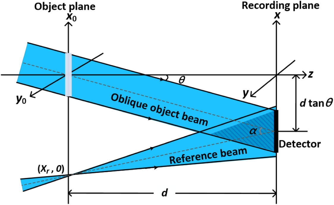
Figure 1.Schematic of LF-TDH coordinate system.
We assume
It is noted that a linear phase shift of
Meanwhile, the DC term
The double exposure method [40] is used to compensate for the additional quadratic phase factor in Eq. (7). The corrected phase is obtained by subtracting the phase distribution, which is reconstructed from a background hologram. This hologram is recorded using identical experimental parameters without the sample. Phase unwrapping is subsequently conducted if necessary by using the least squared method [41]. Theoretically, this method is also available for correcting phase aberration [42], which is not adopted because the reconstruction quality is not as good as the double exposure method in our reconstruction.
3. EXPERIMENTAL RESULTS
A. Experimental Setup
The diagram of the experimental setup is depicted in Fig. 2. A far-infrared
![]()
Figure 2.Schematic of LF-TDH experimental layout.
LF-TDH holograms were recorded by a pyroelectric detector (Pyrocam IV, Ophir-Spiricon, Inc.), with a pixel pitch of
B. Reconstruction Results
1. Resolution of Reconstructed Amplitude Image
To determine the spatial resolution of the LF-TDH setup, a Siemens star with an outer diameter of 20 mm was adopted. A photograph of the sample is given in Fig. 3(a). The sample had a spoke angle of 7.5° and a total of 48 spokes. The opaque spokes were fabricated by sputtering an Au coating on a high-resistivity float zone Si (HRFZ-Si) substrate via photolithography. The thicknesses of the substrate and Au coating are 500 μm and 50 nm, respectively. The resolutions at the outer diameter and the center circle of this target are 0.38 and 7.66 lp/mm, respectively. The illuminated region of the sample is inside the white dashed-line box in Fig. 3(a). For the reconstruction, 500 frames were recorded and accumulated via Gaussian fitting to be a synthesized hologram [25]. Figure 3(b) shows the accumulated hologram. The fringe contrast is the metric to evaluate the quality of the hologram [43], the value of which is 0.682, as shown in the red rectangle in Fig. 3(b).
![]()
Figure 3.Siemens star and its LF-TDH reconstruction results. (a) Photograph of the sample. (b) Accumulated hologram of 500 frames. (c1) Reconstructed amplitude image after a single inverse Fourier transform of (b). (c2) Reconstructed amplitude image after DC term filtering and apodization from (c1). (d1), (d2) The reconstructed amplitude images before and after correction, respectively. White scale bars represent 3 mm.
Figure 3(c1) shows the reconstructed amplitude image of the object after an inverse Fourier transform of the hologram. For better display, it was resized from the original
In this experiment, the gold-coated sample has high reflectivity and fine features. To further suppress the minor residual successive reflections, it was not perfectly parallel to the detector. Therefore, the distortion known as anamorphism should be considered. It is shown in Fig. 3(d1) that the aspect ratio of the length to the width in the reconstructed Siemens star was 1.43. The anamorphism was numerically corrected by adopting a tilted plane correction method [21]. The results can be seen in Fig. 3(d2). Theoretically, the lateral resolution is anisotropic due to the rectangular detector. The highest resolution was
2. Wide-Field Phase Imaging by Image Stitching
It is illustrated in Fig. 4(a) that a polypropylene (PP) plate patterned with letters was adopted as the sample. The length and width of the patterned region are
![]()
Figure 4.LF-TDH reconstruction results of a PP plate. (a) Photograph with schematic pattern. (b1)–(b3) Hologram, the corresponding reconstructed amplitude and phase images, respectively. (b4) The cut-profile of the blue line plotted in (b3). (c) Expanded amplitude distribution by stitching 20 images. (d) The 3D thickness profile distribution of the sample by stitching unwrapped phase images.
The effective FOV of this layout, restrained by the size of the illumination beam, was approximately
3. Real-Time Measurement of Leaf Dehydration
Leaves are the main organ of photosynthesis and transpiration in plants. The changes in their water contents indicate the physiological status of plants. Different from commonly used destructive methods, e.g., gravimetry, THz spectroscopy and imaging have been validated for non-invasively quantifying the water contents of leaves [14,48–52]. Compared with terrestrial herbaceous plants, aquatic leaves have higher water contents, which dehydrate much more rapidly after leaving the water environment. A leaf of
![]()
Figure 5.Dynamic observation results of an aquatic leaf (
Considering the rapid dehydration process of the aquatic leaf, each hologram was obtained by accumulating 30 frames without Gaussian fitting, since 30 frames are statistically insufficient to extract the expectancy of the intensity from the Gaussian statistics. Therefore, the time interval of the adjacent holograms was 0.6 s. The computational time for the complete reconstruction of each hologram, on a desktop personal computer (PC) with 3.4 GHz i5-7500, 8 GB random access memory (RAM), and R2016B MATLAB, was 0.187 s, which is
Several reconstructed amplitude and phase images were extracted at an interval of 40 s, as shown in Figs. 5(b) and 5(c). Obviously, the morphology of the leaf at the initial moment was distinctly different from that in the final moment. At
4. DISCUSSION AND CONCLUSION
We proposed LF-TDH, in which a triangular geometry based on tilted illumination was built. Similar to other TDH approaches based on CW THz sources and array detectors, e.g., in-line TDH and off-axis Fresnel TDH, LF-TDH is a full-field phase imaging approach. However, unlike these TDH approaches, the complex calculation of diffraction propagation is replaced by a single inverse Fourier transform of the hologram so that the speed of reconstruction is obviously accelerated. The proposed layout is different from other lensless holographic geometries at other frequencies. Compared with current lensless Fourier-transform digital holographic layouts, the proposed layout not only avoids drilling holes at the object mask and wasting THz radiation, but also simplifies the interference architecture and squeezes the recording distance for attainable high resolution. In this system, both the object and recording planes are not perpendicular to the optical axis, the emergent beam from the sample was reflected to the opposite direction by the sensor of the detector, and
The theoretical and experimental lateral resolutions of the proposed geometry are 236 μm and 346 μm, respectively. The pixel pitch of the THz array detector, i.e., microbolometers and pyroelectric detector, is smaller than the wavelength of the THz beam. Therefore, the aperture of the detector rather than the pixel pitch is the bottleneck of the lateral resolution of LF-TDH. The use of synthetic aperture is worthy of being investigated to enhance the resolution. Sub-pixel registration and the stitching of overlapped reconstructed images is an effective method to expand the image size. The time interval of temporal adjacent reconstructed images was 0.6 s, while the data acquisition speed, i.e., the chopping frequency of the detector, was 50 Hz. Currently, the bottleneck for the time resolution is the low SNR of the single-frame hologram. For quantitative phase imaging, 30 frames were the minimum accumulation number to get a synthesized THz digital hologram with good fringe contrast. The speed can be easily boosted by replacing the pyroelectric detector with a microbolometer. Both the radiation power fluctuation of the THz laser and the uneven distribution of the THz illumination beam had a negative influence on the fidelity of the individual reconstruction images and the synthesized ones. An appropriate THz spatial filter will help to produce a uniform Gaussian beam.
In summary, LF-TDH has a compact and robust lensless recording layout and simplified reconstruction procedure. Full-field amplitude and phase images can be reconstructed simultaneously. Although the study of dehydration of terrestrial plant leaves is not new at THz frequencies, dynamic detection of an aquatic leaf undergoing rapid dehydration is realized at the THz band for the first time, to the best of our knowledge. The proposed approach is capable of measuring the water variations on the order of sub-seconds in different parts of the leaf from successive amplitude images. When the leaf becomes more transparent to the THz radiation during its dehydration, the changes of the morphology are still clearly revealed by a series of reconstructed phase images. This method provides unprecedented insights into the water dynamics of plants and renders wide applications in THz biomedical imaging. It is noted that the natural evaporation process of the leaf moisture cells may be accelerated by the strong CW THz radiation, which was
APPENDIX A
The hydration change of the leaf is numerically investigated and compared. It is shown in Fig.
![]()
Figure 6.(a) Reference points (black dots) and different-colored rectangular regions are chosen to estimate (b) the movement of leaf of
The amplitude curves of these representative parts and the whole leaf are plotted in Fig.
Through the analysis above, it is noted that the absolute amplitude variation of the leaf tip (blue region) was more pronounced than in other parts of this leaf. Three leaflet tips are selected for further analysis. The changes of the average amplitude and phase in these three parts are illustrated in Figs.
This method relies on the assumption that the absorption of 2.52 THz radiation by the leaf was mainly due to water absorption. The variation of THz transmittance reflects the changes in water content. The Lambert–Beer attenuation law is an effective approach to calculate the water content [
The whole leaf (green curve) and three tips are chosen to plot the decreasing curves of water content in Fig.
References
[1] D. M. Mittleman. Twenty years of terahertz imaging [Invited]. Opt. Express, 26, 9417-9431(2018).
[2] D. Alves-Lima, J. Song, X. Li, A. Portier, Y. Shen, J. A. Zeitler, H. Lin. Review of terahertz pulsed imaging for pharmaceutical film coating analysis. Sensors, 20, 1441(2020).
[3] S. Zhong. Progress in terahertz nondestructive testing: a review. Front. Mech. Eng., 14, 273-281(2019).
[4] Y. Zhang, C. Wang, B. Huai, S. Wang, Y. Zhang, D. Wang, L. Rong, Y. Zheng. Continuous-wave THz imaging for biomedical samples. Appl. Sci., 11, 71(2021).
[5] H. Guerboukha, K. Nallappan, M. Skorobogatiy. Toward real-time terahertz imaging. Adv. Opt. Photon., 10, 843-938(2018).
[6] J. Coutaz, F. Garet, V. P. Wallace. Principles of Terahertz Time-Domain Spectroscopy(2018).
[8] A. Bartels, R. Cerna, C. Kistner, A. Thoma, F. Hudert, C. Janke, T. Dekorsy. Ultrafast time-domain spectroscopy based on high-speed asynchronous optical sampling. Rev. Sci. Instrum., 78, 035107(2007).
[9] H. Guerboukha, A. Markov, H. Qu, M. Skorobogatiy. Time resolved dynamic measurements at THz frequencies using a rotary optical delay line. IEEE Trans. Terahertz Sci. Technol., 5, 564-572(2015).
[10] Q. Wu, T. D. Hewitt, X.-C. Zhang. Two-dimensional electro-optic imaging of THz beams. Appl. Phys. Lett., 69, 1026-1028(1996).
[11] L. Guo, X. Wang, P. Han, W. Sun, S. Feng, J. Ye, Y. Zhang. Observation of dehydration dynamics in biological tissues with terahertz digital holography [Invited]. Appl. Opt., 56, F173-F178(2017).
[12] L. Olivieri, J. S. T. Gongora, L. Peters, V. Cecconi, A. Cutrona, J. Tunesi, R. Tucker, A. Pasquazi, M. Peccianti. Hyperspectral terahertz microscopy via nonlinear ghost imaging. Optica, 7, 186-191(2020).
[13] S. Chen, L. Du, K. Meng, J. Li, Z. Zhai, Z. Li, L. Zhu. Terahertz wave near-field compressive imaging with a spatial resolution of over
[14] R. I. Stantchev, X. Yu, T. Blu, E. Pickwell-MacPherson. Real-time terahertz imaging with a single-pixel detector. Nat. Commun., 11, 2535(2020).
[15] H. Yuan, D. Voß, A. Lisauskas, D. Mundy, H. G. Roskos. 3D Fourier imaging based on 2D heterodyne detection at THz frequencies. APL Photon., 4, 106108(2019).
[16] Y. L. Lim, K. Bertling, T. Taimre, T. Gillespie, C. Glenn, A. Robinson, D. Indjin, Y. Han, L. Li, E. H. Linfield, A. G. Davies, P. Dean, A. D. Rakić. Coherent imaging using laser feedback interferometry with pulsed-mode terahertz quantum cascade lasers. Opt. Express, 27, 10221-10233(2019).
[17] M. Wienold, T. Hagelschuer, N. Rothbart, L. Schrottke, K. Biermann, H. T. Grahn, H. W. Hübers. Real-time terahertz imaging through self-mixing in a quantum-cascade laser. Appl. Phys. Lett., 109, 11102(2016).
[18] L. Valzania, T. Feurer, P. Zolliker, E. Hack. Terahertz ptychography. Opt. Lett., 43, 543-546(2018).
[19] L. Rong, C. Tang, D. Wang, B. Li, F. Tan, Y. Wang, X. Shi. Probe position correction based on overlapped object wavefront cross-correlation for continuous-wave terahertz ptychography. Opt. Express, 27, 938-950(2019).
[20] D. Wang, B. Li, L. Rong, F. Tan, J. J. Healy, J. Zhao, Y. Wang. Multi-layered full-field phase imaging using continuous-wave terahertz ptychography. Opt. Lett., 45, 1391-1394(2020).
[21] L. Rong, C. Tang, Y. Zhao, F. Tan, Y. Wang, J. Zhao, D. Wang, M. Georges. Continuous-wave terahertz reflective ptychography by oblique illumination. Opt. Lett., 45, 4412-4415(2020).
[22] L. Rong, F. Tan, D. Wang, Y. Zhang, K. Li, J. Zhao, Y. Wang. High-resolution terahertz ptychography using divergent illumination and extrapolation algorithm. Opt. Laser Eng., 147, 106729(2021).
[23] Z. Li, Q. Yan, Y. Qin, W. Kong, G. Li, M. Zou, D. Wang, Z. You, X. Zhou. Sparsity-based continuous wave terahertz lens-free on-chip holography with sub-wavelength resolution. Opt. Express, 27, 702-713(2019).
[24] K. Xue, Q. Li, Y. D. Li, Q. Wang. Continuous-wave terahertz in-line digital holography. Opt. Lett., 37, 3228-3230(2012).
[25] L. Rong, T. Latychevskaia, D. Wang, X. Zhou, H. Huang, Z. Li, Y. Wang. Terahertz in-line digital holography of dragonfly hindwing: amplitude and phase reconstruction at enhanced resolution by extrapolation. Opt. Express, 22, 17236-17245(2014).
[26] L. Rong, T. Latychevskaia, C. Chen, D. Wang, Z. Yu, X. Zhou, Z. Li, H. Huang, Y. Wang, Z. Zhou. Terahertz in-line digital holography of human hepatocellular carcinoma tissue. Sci. Rep., 5, 8445(2015).
[27] M. Yamagiwa, T. Minamikawa, F. Minamiji, T. Mizuno, Y. Tokizane, R. Oe, H. Koresawa, Y. Mizutani, T. Iwata, H. Yamamoto, T. Yasui. Visualization of internal structure and internal stress in visibly opaque objects using full-field phase-shifting terahertz digital holography. Opt. Express, 27, 33854-33868(2019).
[28] D. Wang, Y. Zhang, L. Rong, D. Ma, J. Zhao, Y. Wang. Continuous-wave terahertz self-referencing digital holography based on Fresnel’s mirrors. Opt. Lett., 45, 913-916(2020).
[29] M. Locatelli, M. Ravaro, S. Bartalini, L. Consolino, M. S. Vitiello, R. Cicchi, F. Pavone, P. De Natale. Real-time terahertz digital holography with a quantum cascade laser. Sci. Rep., 5, 13566(2015).
[30] M. Yamagiwa, T. Ogawa, T. Minamikawa, D. G. Abdelsalam, K. Okabe, N. Tsurumachi, Y. Mizutani, T. Iwata, H. Yamamoto, T. Yasui. Real-time amplitude and phase imaging of optically opaque objects by combining full-field off-axis terahertz digital holography with angular spectrum reconstruction. J. Infrared Millim. Terahertz Waves, 39, 561-572(2018).
[31] D. Wang, Y. Zhao, L. Rong, M. Wan, X. Shi, Y. Wang, J. T. Sheridan. Expanding the field-of-view and profile measurement of covered objects in continuous-wave terahertz reflective digital holography. Opt. Eng., 58, 023111(2019).
[32] M. Heimbeck, H. Everitt. Terahertz digital holographic imaging. Adv. Opt. Photon., 12, 1-59(2020).
[33] C. Wagner, S. Seebacher, W. Osten, W. Jüptner. Digital recording and numerical reconstruction of lensless Fourier holograms in optical metrology. Appl. Opt., 38, 4812-4820(1999).
[34] M. Kumar, C. Shakher. Experimental characterization of the hygroscopic properties of wood during convective drying using digital holographic interferometry. Appl. Opt., 55, 960-968(2016).
[35] E. B. Malm, N. C. Monserud, C. G. Brown, P. W. Wachulak, H. Xu, G. Balakrishnan, W. Chao, E. Anderson, M. C. Marconi. Tabletop single-shot extreme ultraviolet Fourier transform holography of an extended object. Opt. Express, 21, 9959-9966(2013).
[36] M. M. Hossain, G. Sheoran, V. Kumar, C. Shakher. Contouring of diffused objects using lensless Fourier transform digital Moiré holography. Appl. Opt., 51, 5331-5339(2012).
[37] A. Anand, A. Faridian, V. K. Chhaniwal, S. Mahajan, V. Trivedi, S. K. Dubey, G. Pedrini, W. Osten, B. Javidi. Single beam Fourier transform digital holographic quantitative phase microscopy. Appl. Phys. Lett., 104, 103705(2014).
[38] S. Agarwal, V. Kumar, C. Shakher. Temperature measurement of wick stabilized micro diffusion flame under the influence of magnetic field using digital holographic interferometry. Opt. Laser Eng., 102, 161-169(2018).
[39] J. W. Goodman. Introduction to Fourier Optics, 126-165(2005).
[40] P. Ferraro, S. De Nicola, A. Finizio, G. Coppola, S. Grilli, C. Magro, G. Pierattini. Compensation of the inherent wave front curvature in digital holographic coherent microscopy for quantitative phase-contrast imaging. Appl. Opt., 42, 1938-1946(2003).
[41] M. D. Pritt, J. S. Shipman. Least-squares two-dimensional phase unwrapping using FFT’s. IEEE Trans. Geosci. Remote Sens., 32, 706-708(1994).
[42] J. Di, J. Zhao, W. Sun, H. Jiang, X. Yan. Phase aberration compensation of digital holographic microscopy based on least squares surface fitting. Opt. Commun., 282, 3873-3877(2009).
[43] M. Born, E. Wolf. Principles of Optics, 1-70(1999).
[44] C. Liu, Y. Li, X. Cheng, Z. Liu, F. Bo, J. Zhu. Elimination of zero-order diffraction in digital holography. Opt. Eng., 41, 2434-2437(2002).
[45] F. J. Harris. On the use of windows for harmonic analysis with the discrete Fourier transform. Proc. IEEE, 66, 51-83(1978).
[46] Y. Jin, G. Kim, S. Jeon. Terahertz dielectric properties of polymers. J. Korean Phys. Soc., 49, 513-517(2006).
[47] M. Guizar-Sicairos, S. T. Thurman, J. R. Fienup. Efficient subpixel image registration algorithms. Opt. Lett., 33, 156-158(2008).
[48] B. B. Hu, M. C. Nuss. Imaging with terahertz waves. Opt. Lett., 20, 1716-1718(1995).
[49] Z. Song, S. Yan, Z. Zhang, Y. Fu, D. Wei, H. Cui, P. Lai. Temporal and spatial variability of water status in plant leaves by terahertz imaging. IEEE Trans. Terahertz Sci. Technol., 8, 520-527(2018).
[50] C. Jördens, M. Scheller, B. Breitenstein, D. Selmar, M. Koch. Evaluation of leaf water status by means of permittivity at terahertz frequencies. J. Biol. Phys., 35, 255-264(2009).
[51] R. Gente, M. Koch. Monitoring leaf water content with THz and sub-THz waves. Plant Methods, 11, 15(2015).
[52] L. Baldacci, M. Pagano, L. Masini, A. Toncelli, G. Carelli, P. Storchi, A. Tredicucci. Non-invasive absolute measurement of leaf water content using terahertz quantum cascade lasers. Plant Methods, 13, 51(2017).
[53] M. Izumi, H. Ishida, S. Nakamura, J. Hidema. Entire photodamaged chloroplasts are transported to the central vacuole by autophagy. Plant Cell, 29, 377-394(2017).
[54] H. B. Zhang, K. Mitobe, N. Yoshimura. Application of terahertz imaging to water content measurement. Jpn. J. Appl. Phys., 47, 8065-8070(2008).


Set citation alerts for the article
Please enter your email address

© Copyright 2018-2021 | Chinese Laser Press. All Rights Reserved 沪ICP备15018463号-20