• Photonics Research
  • Vol. 9, Issue 9, 1758 (2021)
Danping Pan1、†, Lei Wan1、2、†, Min Ouyang1, Wei Zhang1, Alexander A. Potapov1, Weiping Liu1, Zixian Liang3, Tianhua Feng1、6、*, and Zhaohui Li4、5、7、*
Author Affiliations
  • 1Department of Electronic Engineering, College of Information Science and Technology, Jinan University, Guangzhou 510632, China
  • 2Wuhan National Laboratory for Optoelectronics, Huazhong University of Science and Technology, Wuhan 430074, China
  • 3Institute of Microscale Optoelectronics, Shenzhen University, Shenzhen 518060, China
  • 4State Key Laboratory of Optoelectronic Materials and Technologies and School of Electronics and Information Technology, Sun Yat-sen University, Guangzhou 511400, China
  • 5Southern Marine Science and Engineering Guangdong Laboratory (Zhuhai), Zhuhai 519000, China
  • 6e-mail: thfeng@jnu.edu.cn
  • 7e-mail: lzhh88@sysu.edu.cn
  • show less
    DOI: 10.1364/PRJ.426827 Cite this Article Set citation alerts
    Danping Pan, Lei Wan, Min Ouyang, Wei Zhang, Alexander A. Potapov, Weiping Liu, Zixian Liang, Tianhua Feng, Zhaohui Li. Laplace metasurfaces for optical analog computing based on quasi-bound states in the continuum[J]. Photonics Research, 2021, 9(9): 1758 Copy Citation Text show less
    (a) Illustration of a dielectric metasurface transforming an input 2D spatial function to another function as a Laplace operator; (b) unit cell of the dielectric metasurface. Left, 3D view of the unit cell. It consists of a Si brick (light blue color) with a thickness of h=163 nm and a glass substrate (gray color). Right, top view of the unit cell. The period is a=331 nm, and the width of Si brick is d=251 nm. There are four square voids with a width of s=33 nm at the centers of all edges. (c) Transmission coefficient spectra of the Laplace metasurface at different incident angles along x direction for a p wave.
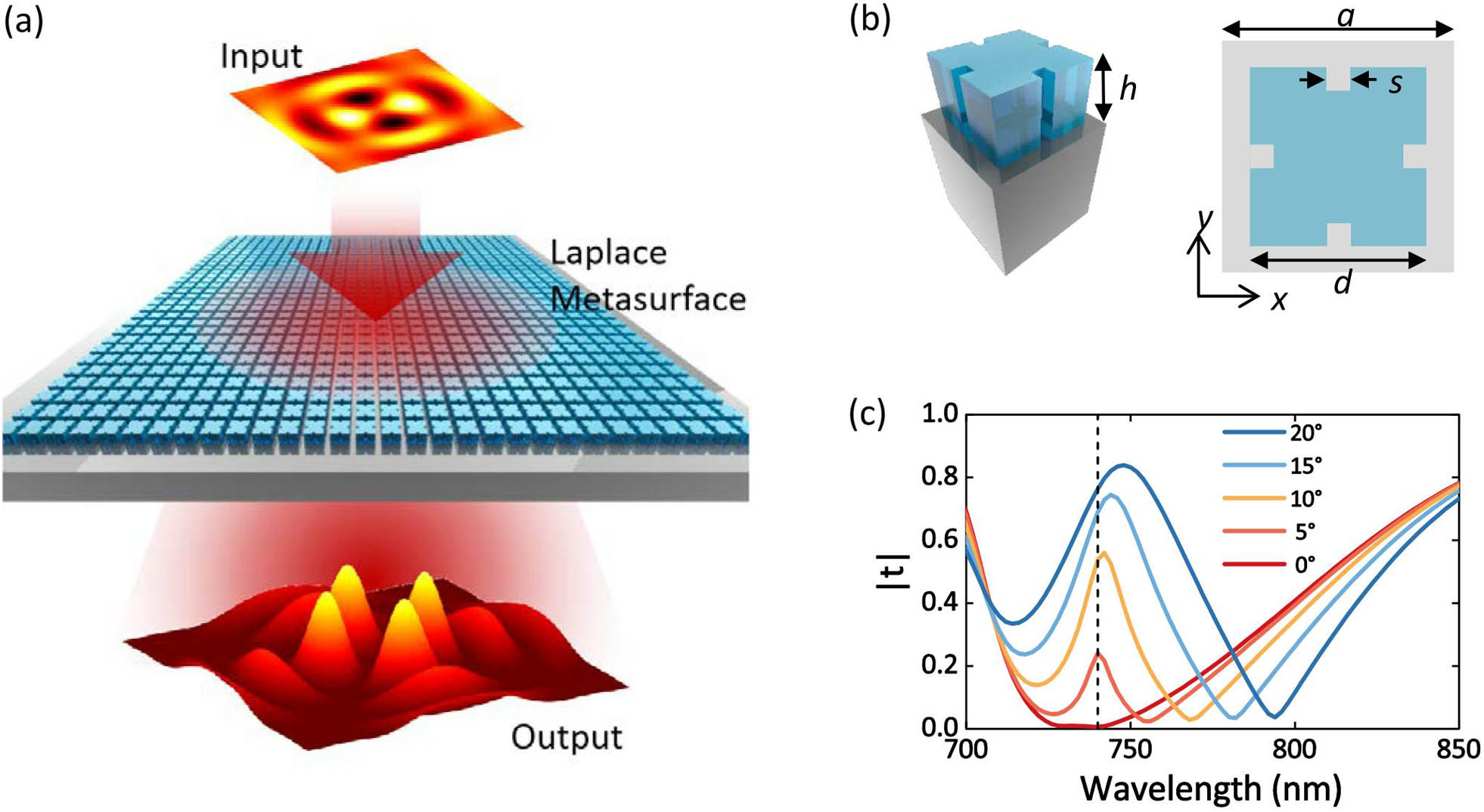
    Fig. 1. (a) Illustration of a dielectric metasurface transforming an input 2D spatial function to another function as a Laplace operator; (b) unit cell of the dielectric metasurface. Left, 3D view of the unit cell. It consists of a Si brick (light blue color) with a thickness of h=163  nm and a glass substrate (gray color). Right, top view of the unit cell. The period is a=331  nm, and the width of Si brick is d=251  nm. There are four square voids with a width of s=33  nm at the centers of all edges. (c) Transmission coefficient spectra of the Laplace metasurface at different incident angles along x direction for a p wave.
    (a) Dispersion bands around 740 nm of the proposed dielectric metasurface Laplace operator in both ΓX and ΓM directions. The band of interest highlighted with red corresponds to the quasi-BIC. The inset shows the irreducible Brillouin zone. (b) Corresponding Q factors of the five bands in (a). The red color corresponds to the quasi-BIC band. (c) Ez field distribution of the BIC at the Γ point. Top panel, top view at the central plane of the unit cell; bottom panel, cross-sectional view at the central plane of the unit cell. The yellow dashed lines highlight the profile of the structure, while the green arrows indicate the electric field. The red and blue colors represent the positive and negative values, respectively. (d) and (e) Transmittance spectra as functions of the incident angle for the p polarization in the ΓX and ΓM directions, respectively.
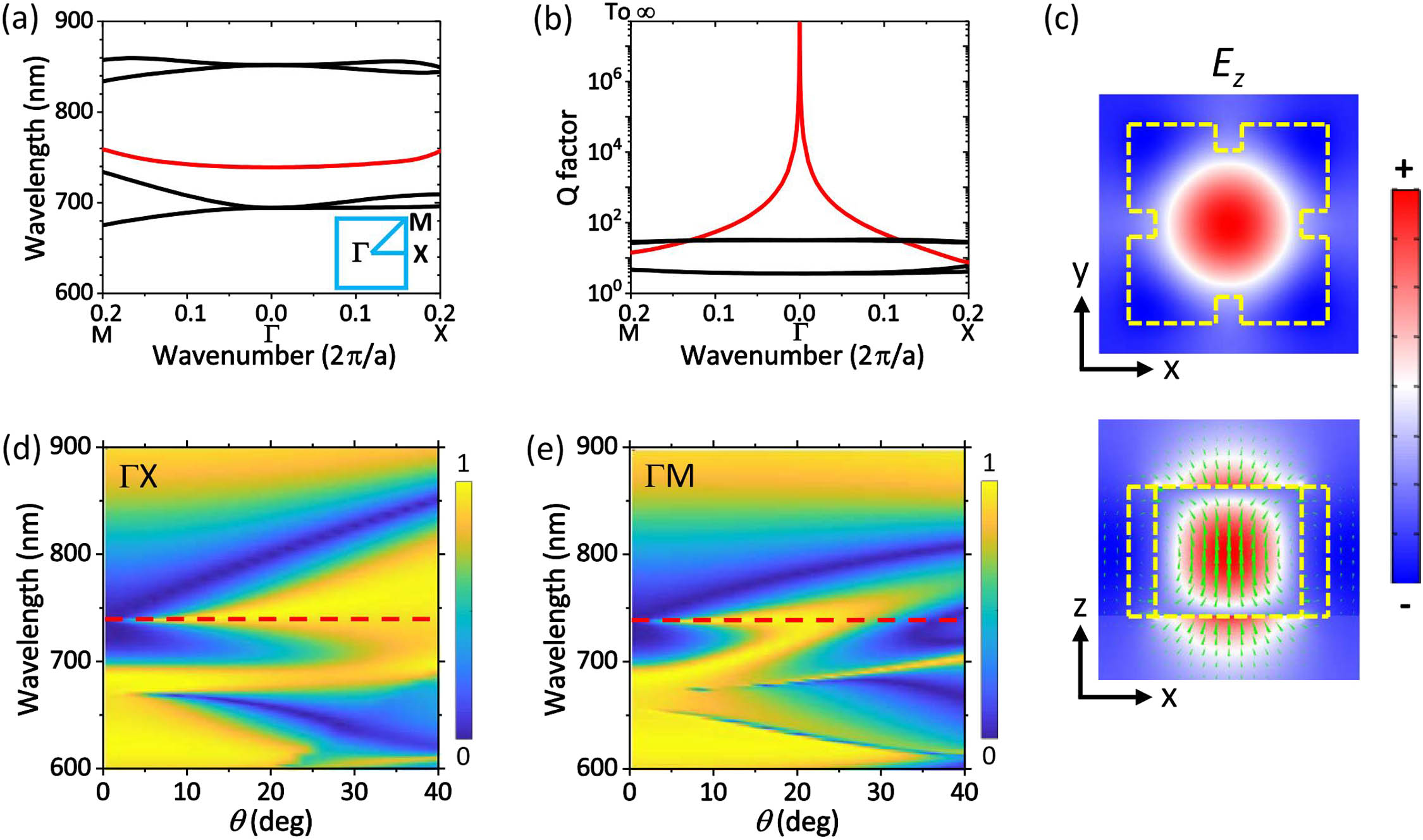
    Fig. 2. (a) Dispersion bands around 740 nm of the proposed dielectric metasurface Laplace operator in both ΓX and ΓM directions. The band of interest highlighted with red corresponds to the quasi-BIC. The inset shows the irreducible Brillouin zone. (b) Corresponding Q factors of the five bands in (a). The red color corresponds to the quasi-BIC band. (c) Ez field distribution of the BIC at the Γ point. Top panel, top view at the central plane of the unit cell; bottom panel, cross-sectional view at the central plane of the unit cell. The yellow dashed lines highlight the profile of the structure, while the green arrows indicate the electric field. The red and blue colors represent the positive and negative values, respectively. (d) and (e) Transmittance spectra as functions of the incident angle for the p polarization in the ΓX and ΓM directions, respectively.
    (a) Transmittance amplitudes of the Laplace metasurface as functions of the incidence angle along both ΓX (red solid lines) and ΓM (red dotted lines) directions for a p wave at the wavelength of 740 nm. The ideal results (black dashed lines) are fitted from those along the ΓX. (b) Corresponding phases of the Laplace metasurface and the ideal case. A reference plane is purposefully set to make the value as −π at normal incidence. (c) 2D transmittance amplitudes as functions of incidence angle. The equal-transmittance contours (black lines) resemble well-defined circles, indicating good isotropic properties. (d) Corresponding 2D transmittance phases of the Laplace metasurface.
    Fig. 3. (a) Transmittance amplitudes of the Laplace metasurface as functions of the incidence angle along both ΓX (red solid lines) and ΓM (red dotted lines) directions for a p wave at the wavelength of 740 nm. The ideal results (black dashed lines) are fitted from those along the ΓX. (b) Corresponding phases of the Laplace metasurface and the ideal case. A reference plane is purposefully set to make the value as π at normal incidence. (c) 2D transmittance amplitudes as functions of incidence angle. The equal-transmittance contours (black lines) resemble well-defined circles, indicating good isotropic properties. (d) Corresponding 2D transmittance phases of the Laplace metasurface.
    (a) 1D spatial function with three Gaussian envelopes as the input light field; (b) output results after the operation of ideal second-order differentiation; (c) output results from the Laplace metasurface. Both OTFs along the ΓX (solid line) and ΓM(symbols) directions were considered. Here the pixel size of input is 3.6λ.
    Fig. 4. (a) 1D spatial function with three Gaussian envelopes as the input light field; (b) output results after the operation of ideal second-order differentiation; (c) output results from the Laplace metasurface. Both OTFs along the ΓX (solid line) and ΓM(symbols) directions were considered. Here the pixel size of input is 3.6λ.
    (a) Input 2D spatial function for Laplace operation; (b) analytical solution of the input function; (c) output from the Laplace metasurface; (d)–(f) radial profiles of the corresponding functions along x direction at y=1800λ in (a)–(c), respectively; (g)–(i) angular profiles of the corresponding functions at r=576λ in (a)–(c), respectively. Here all the pixel sizes are set to be 3.6λ.
    Fig. 5. (a) Input 2D spatial function for Laplace operation; (b) analytical solution of the input function; (c) output from the Laplace metasurface; (d)–(f) radial profiles of the corresponding functions along x direction at y=1800λ in (a)–(c), respectively; (g)–(i) angular profiles of the corresponding functions at r=576λ in (a)–(c), respectively. Here all the pixel sizes are set to be 3.6λ.
    (a) False-color image of a traffic sign; (b) corresponding gray-scale image as the input; (c) and (d) output image from the ideal Laplace operation and the Laplace metasurface corresponding to (b), respectively.
    Fig. 6. (a) False-color image of a traffic sign; (b) corresponding gray-scale image as the input; (c) and (d) output image from the ideal Laplace operation and the Laplace metasurface corresponding to (b), respectively.
    (a) OTF of the metasurface under the s-wave illumination; (b) corresponding transmittance phases. A reference plane is purposefully set to make the phase value at the normal incidence as −π. (c) and (d) OTFs for the cases of polarization conversion with the p- and s-wave incidences, respectively.
    Fig. 7. (a) OTF of the metasurface under the s-wave illumination; (b) corresponding transmittance phases. A reference plane is purposefully set to make the phase value at the normal incidence as π. (c) and (d) OTFs for the cases of polarization conversion with the p- and s-wave incidences, respectively.
    (a) 2D transmittance amplitudes as functions of incidence angle under the p wave illumination at 740 nm. The equal-transmittance contours from inner to outer indicate the transmittance from 0.1 to 0.7 at a step of 0.1. (b) Corresponding phases. A reference plane is purposefully set to make the phase value at the normal incidence as −π.
    Fig. 8. (a) 2D transmittance amplitudes as functions of incidence angle under the p wave illumination at 740 nm. The equal-transmittance contours from inner to outer indicate the transmittance from 0.1 to 0.7 at a step of 0.1. (b) Corresponding phases. A reference plane is purposefully set to make the phase value at the normal incidence as π.
    (a) 2D transmittance of a Laplace metasurface at the wavelength of 1550 nm under the p-wave illumination; (b) corresponding 2D transmittance under the s-wave illumination; (c) transmittance of the s wave under a p-wave incidence; (d) transmittance of the p wave under an s-wave incidence.
    Fig. 9. (a) 2D transmittance of a Laplace metasurface at the wavelength of 1550 nm under the p-wave illumination; (b) corresponding 2D transmittance under the s-wave illumination; (c) transmittance of the s wave under a p-wave incidence; (d) transmittance of the p wave under an s-wave incidence.
    (a) Real part of the electric field of the input light field; (b) analytical solution of the Laplace operation on the input; (c) output from the Laplace metasurface; (d)–(f) radial profiles of the corresponding functions along the x direction at y=1800λ in (a)–(c), respectively.
    Fig. 10. (a) Real part of the electric field of the input light field; (b) analytical solution of the Laplace operation on the input; (c) output from the Laplace metasurface; (d)–(f) radial profiles of the corresponding functions along the x direction at y=1800λ in (a)–(c), respectively.
    (a) Input image consisting of a QR code; (b) output image of the ideal Laplace operation; (c) output from the Laplace meatsurface. All images are the light-intensity profile; the pixel sizes are set as 2.88λ.
    Fig. 11. (a) Input image consisting of a QR code; (b) output image of the ideal Laplace operation; (c) output from the Laplace meatsurface. All images are the light-intensity profile; the pixel sizes are set as 2.88λ.
    Danping Pan, Lei Wan, Min Ouyang, Wei Zhang, Alexander A. Potapov, Weiping Liu, Zixian Liang, Tianhua Feng, Zhaohui Li. Laplace metasurfaces for optical analog computing based on quasi-bound states in the continuum[J]. Photonics Research, 2021, 9(9): 1758
    Download Citation