Abstract
In this paper, we present an ultra-compact 1D photonic crystal (PhC) Bragg grating design on a thin film lithium niobate slot waveguide (SWG) via 2D- and 3D-FDTD simulations. 2D-FDTD simulations are employed to tune the photonic bandgap (PBG) size, PBG center, cavity resonance wavelength, and the whole size of PhC. 3D-FDTD simulations are carried out to model the real structure by varying different geometrical parameters such as SWG height and PhC size. A moderate resonance quality factor of about 300 is achieved with a PhC size of only . The proposed slot Bragg grating structure is then exploited as an electric field (E-field) sensor. The sensitivity is analyzed by 3D-FDTD simulations with a minimum detectable E-field as small as . The possible fabrication process of the proposed structure is also discussed. The compact size of the proposed slot Bragg grating structure may have applications in on-chip E-field sensing, optical filtering, etc.1. INTRODUCTION
Highly sensitive electric field (E-field) sensing has an increasing demand in many areas ranging from automotive, avionic, military to EEG or ECG signal detection [1]. Oftentimes, the conventional E-field sensor is made of CMOS-compatible materials such as silicon, where a large quantity of metallic materials is used for the design of electrodes. On the one hand, the employed material, silicon, lacks the linear electro-optic (EO) effect. Therefore, the mechanism exploited to detect the E-field is a free-carrier-induced refractive index variation, which brings limits in high-frequency and high-sensitivity E-field sensing applications. On the other hand, the common structure employed in the conventional E-field sensor is typically based on Mach–Zehnder interferometric configurations. In order to obtain high sensitivity, a length of several millimeters to centimeters is needed; thus, it contains a large quantity of metal that acts as antennas, which will bring distortions to the E-field to be detected. As for the choice of material, lithium niobate (LN) is suitable for developing a photonic E-field sensor due to its large EO coefficient [2]. Thanks to the commercially available thin film lithium niobate (TFLN) [3], ultra-compact nano-waveguiding of different configurations on LN can be possible [4]. Among them, a slot waveguide (SWG) provides high light enhancement; therefore, it is a promising waveguide (WG) configuration for developing highly sensitive E-field sensors.
Since the first report of the SWG by Lipson [5], world-wide efforts have been made in investigating SWG for various applications, notably in nonlinear effect enhancement [6,7] and highly sensitive sensors [8,9]. Most often, SWG is combined with active materials such as EO polymers or with photonic crystals (PhCs) in order to obtain the desired functionalities. For example, using frequency domain OCT, Caër et al. experimentally demonstrated that slotted PhC WG (PWG) can focus light to an effective area down to , which is about tenfold smaller than the diffraction limit [6]. The Kerr/TPA balances in both standard PCW and polymer-filled slot PCW are investigated in which a free-carrier penalty on the nonlinear performance tends to decrease with the increase of the slowing-down factor in slotted PCW [7]. Due to the nanometric size, SWG oftentimes combines with 1D PhC Bragg gratings to design active optical components. In [8], a gold film slot Bragg grating on a silicon WG is proposed as a refractive index sensor with a sensitivity of . Wang et al. experimentally demonstrated a phased-shifted Bragg grating with a quality factor up to fabricated by a CMOS-compatible fabrication technique [9]. Most of the literature is focused on silicon or other CMOS-compatible materials; however, there are few reports on LN-based SWG active optical components. Encouraged by the fruitful results in slotted photonics, we present here a study of LN SWG with PhC in order to design a highly sensitive ultra-compact integrated on-chip E-field sensor. Specifically, a Fabry–Perot (F-P) like PhC cavity in slot Bragg grating is studied in order to design an E-field sensor through the investigation of the resonance wavelength shift with respect to the E-field strength.
The paper is structured as follows: In the second section, 2D-FDTD simulations are performed to find a suitable configuration of PhC structure on SWG. In the third section, 3D-FDTD simulations of the real structure geometries are carried out to further optimize the PhC design. In the fourth section, sensitivity analysis of employing the proposed structure as an E-field sensor is presented. The last section presents a discussion on the possible fabrication process.
Sign up for Photonics Research TOC. Get the latest issue of Photonics Research delivered right to you!Sign up now
2. 2D-FDTD SIMULATIONS OF BRAGG GRATING DESIGN IN SWG
From the SWG systematical study of Ref. [4], we can see that structure parameters of a silicon rail width and an LN slot width shows superior ability to confine light in an LN slot compared with other configurations. This WG structure parameter is then chosen to be the host WG [schematically shown in Fig. 1(a) with parameters fixed at LN slot and the silicon rail width of ] for the following PhC design.
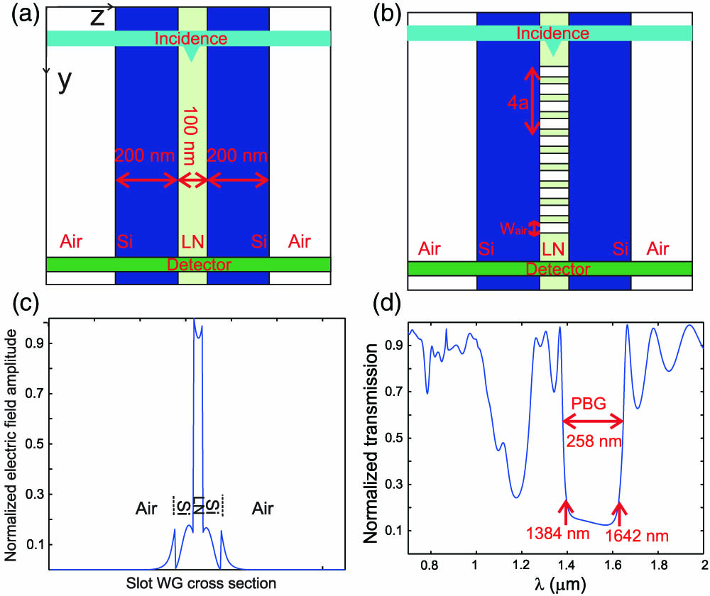
Figure 1.(a) Sketch of 2D SWG considered in the 2D-FDTD simulations. (b) Sketch of 2D slot Bragg grating structure considered in the 2D-FDTD simulations. Period of grating and width of air groove is denoted in the figure. (c) Incident E-field profile in the 2D-FDTD slot Bragg grating simulations. The LN slot, silicon rails, and air ambient medium are denoted, respectively, in the figure. (d) Normalized transmission of 2D slot Bragg grating structure with parameters of , , and the number of air grooves .
2D-PhC design is the most commonly considered choice in PhC nano-patterning due to the fact that it is easier for fabrication, and it possesses comparable properties to that of 3D PhC structures. Empirically speaking, a filling factor (hole radius to period ratio) of at least about 0.3 is needed to open up a photonic bandgap (PBG) in LN air holes 2D-PhC structure. For a structure operating at the vicinity of 1.55 μm telecommunication wavelength, a filling factor of 0.3 would then require a PhC period of about 500 nm, which is a large value compared with the total SWG width of 500 nm. Therefore, a 1D PhC Bragg grating is considered to design on an SWG. 2D-FDTD methods are employed to investigate the Bragg grating design on SWG because it can model the finite size of gratings. These 2D simulations are carried out aiming at creating a large PBG and a cavity resonance centering at the vicinity of 1.55 μm, which makes it compatible with most of the devices in the telecommunication industry.
The structures considered in 2D-FDTD are schematically shown in Figs. 1(a) and 1(b) in which we can see the SWG top view surrounded by air. An incident signal is placed at the entrance of the WG [turquoise rectangle in Figs. 1(a) and 1(b)], while the detector is placed at the output of the WG [green rectangle in Figs. 1(a) and 1(b)]. In order to efficiently excite the WG mode, the incident signal is taken as a pulse wave with an E-field amplitude profile ( polarized) as that in the guided mode distributions, which are shown in Fig. 1(c). The energy flux propagating through the detector is calculated. The normalization of the transmission spectrum is performed by the corresponding energy flux propagating along the unstructured SWG without a Bragg grating. Uniform meshing is applied with . Simulations on how the PBG varies with the geometrical parameters are studied by fixing the number of air grooves , the period (or pitch) of the grating , while the width of air grooves is varying. Normalized transmission of a structure with parameters of , is shown in Fig. 1(d). It yields a PBG width of about 250 nm with a PBG centered around 1480 nm. Simulation results of how the PBG size varies with different filling factors (by varying air groove width value as 70, 100, 140, 170, 200, 240, and 270 nm) are summarized in Table 1. As we can see, a filling factor () varying between 0.3 and 0.7 yields a PBG size larger than 200 nm, which is large enough to host a resonance mode inside. In fact, a large PBG size can be beneficial for the experimental detection because it might degrade to a smaller size due to the fabrication defects. Taking into account the easiness of fabrication, a larger air groove width is preferable. Henceforth, from the above simulations a filling factor is set to be about 0.7.
| Wair | Wair/a | PBG Size | PBG Center |
| 70 | 0.209 | 154 | 1639 |
| 100 | 0.294 | 222 | 1613 |
| 140 | 0.411 | 250 | 1573 |
| 170 | 0.5 | 232 | 1542 |
| 200 | 0.588 | 258 | 1477 |
| 240 | 0.705 | 232 | 1472 |
| 270 | 0.794 | 190 | 1441 |
Table 1. PBG Size of 10 Air Grooves, while Varying the Value of (Units in nm)
Simulations of tuning the PBG center at the wavelength of 1.55 μm are performed with different sets of parameters while the filling factor is fixed to around 0.7. The results are summarized in Table 2. As shown in bold, a structure with parameters of and yields a PBG size of 274 nm centered around 1550 nm. Therefore, parameters of the grating pitch and the filling factor have been set to these values.
| a and Wair | Wair/a | PBG Size | PBG Center |
| a=350, Wair=240 | 0.6857 | 252 | 1508 |
| a=370, Wair=260 | 0.7027 | 274 | 1555 |
| a=390, Wair=270 | 0.69 | 296 | 1612 |
| a=400, Wair=280 | 0.7 | 304 | 1634 |
| a=440, Wair=310 | 0.7 | 342 | 1732 |
Table 2. PBG Center Varying with and while Keeping Around 0.7 (Units in nm)
In the next step, an F-P cavity is created by introducing a defect in the above-determined Bragg grating design. The structure is schematically shown in Fig. 2(a). The number of air grooves on each side of the cavity is set to 5 in order to achieve a good light coupling efficiency to the defect mode.

Figure 2.(a) Sketch of 2D slot Bragg gating structure with a defect size of in the 2D-FDTD simulations. The period of grating and the width of air groove is denoted in the figure. (b) Normalized transmission of 2D slot Bragg grating structure with a symmetric F-P cavity with the parameters of , , , and number of air grooves on each side of defect .
The normalized transmission curve shown in Fig. 2(b) corresponds to a defect size structure. The cavity has a resonance peak wavelength at 1556 nm and a normalized transmittance of about 0.96, which is highlighted by a red rectangle in Fig. 2(b). Continuous wave (CW) simulations are performed to obtain E-field distributions at wavelengths of on-resonance and off-resonance. In Fig. 3(a), corresponding to a CW simulation at resonance peak wavelength of 1556 nm, light is coupled and confined in the cavity region. On the contrary, in Fig. 3(b), corresponding to a CW simulation at off-resonance wavelength of 1650 nm, light is reflected by the PhC mirror. Even though most of the light is reflected back at the off-resonance wavelength excitation, there is still a little portion of light that propagates through the PhC region due to the limited reflection coefficient of the PhC mirror and the lateral losses by grating structures.
Figure 3.E-field amplitude distribution of component along the Bragg grating structures [the black lines show the contour of the structures with the same parameters as in Fig. 2(b)] with excitation wavelength at (a) resonance peak wavelength of 1556 nm, (b) off-resonance wavelength of 1650 nm.
The criteria of choosing the defect size not only depends on the properties of the cavity modes such as the transmittance and resonance wavelength but also requires that the cavity mode has strong light confinement ability. An optical field factor , defined as a mean value of the light confinement ability, is employed for this light confinement quantification [10–14]. It is estimated as the ratio of E-field amplitude integration over all the LN cavity region in the PhC structure to the same quantity but integrated on the unstructured LN as follows:
In order to calculate , two CW calculations with the same illumination conditions at the resonance peak wavelength, one with the PhC structure and the other with non-patterned LN, should be conducted. Here, we investigate how the light confinement varies with different defect sizes; henceforth, the integration region is taken only over the defect region with a length of , as shown in Fig. 2(a).
How resonance properties vary with different defect sizes is summarized in Table 3. As shown in bold, a Bragg grating with a defect size of 290 nm yields a cavity mode at 1556 nm, 96% of transmittance, and a of 4.03. A rather high transmittance () is obtained for all the different defect size simulations conducted with the parameters listed in the table. This is due to the fact that only five air grooves are chosen to form the PhC mirrors, thus yielding a high coupling efficiency to the resonance mode and a high transmittance. Notice that the defect sizes largely affect the resonance wavelength. A smaller defect size produces a resonance at smaller wavelength values, while it shifts to larger values with a larger defect size. Optical field factor reaches its maximum value with the configuration of , meaning that a high light confinement can be obtained. Henceforth, the defect size is set to for the rest of the optimization.
| Wd (nm) | λpeak | Transmittance at λpeak | fopt¯ |
| 210 | 1474 | 0.955 | 3.27 |
| 260 | 1524 | 0.954 | 3.98 |
| 290 | 1556 | 0.962 | 4.03 |
| 310 | 1578 | 0.961 | 3.87 |
| 360 | 1630 | 0.975 | 3.24 |
| 410 | 1674 | 0.978 | 2.53 |
Table 3. Resonance Properties Versus the Defect Size
Prior to 3D real structure modeling, different numbers of air grooves are investigated in 2D calculations in order to see how they may affect the resonance properties. Table 4 summarizes the results of these studies. As shown in bold, a structure with six air grooves yields the highest of 6.31. It resonates at 1554 nm with a transmittance of 91%. We can see that the number of the air grooves does not affect the resonance wavelength position, while the transmittance drops dramatically with the numbers of air groove increases due to the poorer coupling efficiency to the cavity mode.
| N | λpeak | Transmittance at λpeak | fopt¯ |
| 4 | 1556 | 0.949 | 2.45 |
| 5 | 1556 | 0.962 | 4.03 |
| 6 | 1554 | 0.913 | 6.31 |
| 7 | 1554 | 0.668 | 5.08 |
| 8 | 1554 | 0.378 | 5.74 |
Table 4. Resonance Properties Versus the Number of Air Grooves
3. 3D-FDTD SIMULATIONS OF BRAGG GRATING DESIGN IN SWG
The 2D-FDTD simulation results provide a general rule on how each parameter affects the grating performance and narrows down the structural parameters for 3D-FDTD optimization. Henceforth, 3D-FDTD simulations will first start with the optimized parameters determined from the 2D modeling.
The structure modeled in 3D simulations is schematically shown in Fig. 4(a). Guided mode distribution ( polarized) is injected on a plane perpendicular to the WG in the plane. Detection is calculated as the specular transmission at the output ( plane) of the SWG Bragg grating structure. In order to efficiently excite the WG mode, the incident signal is taken as the SWG mode profile obtained from the mode calculations. Without being specifically stated, the specular transmission (also referred to as the zero-order transmission) through the detector plane is calculated via Fourier transforming of the time-varying EM field signals. The normalization of the transmission spectrum is performed by the corresponding transmission through the unpatterned 3D SWG.
Figure 4.(a) Sketch of 3D simulated structure. (b) Zero-order normalized transmission of 3D slot Bragg grating structure with different numbers of air grooves on each side of the F-P cavity.
Because the meshing of the structure cannot be as fine as that in the 2D case, parameters optimized from 2D simulations are therefore rounded to values that can match a coarser meshing ( and ) in 3D modeling. Simulations are first carried out to vary the numbers of air grooves to see how they affect the transmittance. The results of zero-order transmission shown in Fig. 4(b) are obtained with structure parameters as follows: , , , , , and a varying number of air grooves on each side of the defect , 7, 8, and 9. As the air groove number is larger than 7, the transmittance decreases dramatically while the resonance gets slightly narrower. In the red curve case, corresponding to seven air grooves, an efficient transmittance of 0.59 at 1489 nm is obtained. Therefore, the following simulations will start with seven air grooves.
As indicated in the 2D simulations, varying the defect size can tune the resonance wavelength. Henceforth, in order to set the operation wavelength at 1.55 μm, simulations with different defect sizes are carried out, and the results are shown in Fig. 5. Notice that the defect size not only affects the resonance wavelength but also plays a role in the transmittance. A high transmittance is obtained with a defect size around 340 nm, while it decreases, as the defect size differs from this value. A transmittance higher than 0.9 can yield a good coupling efficiency of the resonance. As shown in the gray curve in Fig. 5, defect size of yields a resonance at 1554 nm with 0.88 transmittance, which is a good candidate for further design optimization.
Figure 5.3D-FDTD simulated zero-order normalized transmission with structure parameters as , , , , , number of air grooves on each side of defect and varying defect size .
The above modeled 3D SWG is considered with an of TFLN etched away, while there is still 200 nm of TFLN left on the substrate. Now we will investigate different etching depths of the thin film ( and 700 nm) in order to see its structural tolerance of the above-shown resonance effect. The grating parameters employed for these simulations are the same as the above optimized one for SWG with , while the defect size is varied in order to investigate its effects on the resonance properties. The results are shown in Figs. 6(a) and 6(b) for and 700 nm, respectively. We can note that the defect size has little effect on the size and shape of the PBG, while a larger defect size yields a higher transmittance. Concerning the effect of different etching depth in Fig. 6(a), corresponding to , only a narrow PBG without decreasing down to zero transmittance can be found. This might be due to the fact that part of the WG mode still lies in the unetched TFLN, leading to the poor interaction between WG mode and the grating structure and, consequently, poor quality of the PBG. While in Fig. 6(b), corresponding to , the transmission inside the PBG almost goes down to zero, and a more pronounced PBG can be obtained. We can see that the defect size can greatly change the resonance wavelength but slightly affects the transmission level. Regarding the resonance value in the structure of different etching depths, it increases with the increasing of the etching depth where decreases from 309 for [orange curve in Fig. 6(b)] down to for [green curve in Fig. 6(a)].
Figure 6.3D-FDTD zero-order normalized transmission of slot Bragg grating structure with parameters of , , , and the number of air grooves on each side of defect and with (a) slot etching depth while varying , 360 and 380 nm. (b) Slot etching depth while varying , 340, 360, and 400 nm.
The narrow PBG together without decreasing down to zero transmittance inside the gap makes the resonance inside the PBG difficult to be recognized. Therefore, we can conclude that the etching depth should be at least larger than 500 nm in order to yield a large PBG with an almost zero transmittance inside the gap zone.
A possible fabrication defect on the silicon height (being higher than that of LN etching depth) will degrade the light confinement ability of the structure. Here, a grating design with the presence of a thin layer of upper silicon, as shown in Fig. 7(a), is investigated. The air grooves are etched until reaching the depth of . The upper thin silicon cover thickness is studied by varying it as 40, 60, 80, and 100 nm. The results are shown in Fig. 7(b). With the presence of the upper silicon layer, resonance wavelength shifts to larger values (due to higher effective index of the guided mode) along with the decreasing of the transmittance. As for the resonance value, it slightly decreases from for [black curve in Fig. 7(b)] down to for [gray curve in Fig. 7(b)]. Nevertheless, this upper silicon layer does not significantly degrade the grating properties if the thickness is less than about 50 nm.
Figure 7.(a) Sketch of Bragg grating with silicon height larger than LN slot height. The air grooves etching depth equal to . (b) 3D-FDTD simulated zero-order normalized transmission with structure parameters as , , , , , number of air grooves on each side of defect , , and varying the silicon height .
4. SENSITIVITY ANALYSIS OF SLOT BRAGG GRATING AS AN E-FIELD SENSOR
As mentioned in the Introduction, one possible application of the modeled structure would be an E-field sensor. In this section, the sensitivity of exploiting the slot Bragg grating structure as an E-field sensor through EO effect is analyzed. By only taking into account the largest EO coefficient of LN material, the refractive index variation introduced by the E-field to be detected can be quantified as follows: where is the extraordinary refractive index of LN, which is 2.138 at the wavelength of 1550 nm and is the E-field to be detected along the direction at the point of the PhC probe with a volume size of .
In a slot Bragg grating structure, [see Fig. 4(a)] is the major E-field component; thus, the crystalline direction should be oriented along this direction in order to exploit the largest EO effect. Consequently, -or -cut wafers of LN can be considered for the experimental realization. When LN is designed with a high light confinement PhC nano-patterned structure, the induced EO effect (and therefore the sensitivity) can be enhanced. Combined with the optical field enhancement factor , the corresponding induced refractive index variation in PhC structure can be quantified as
In order to calculate the optical field factor and the mapping relationship between versus refractive index variation , 3D-FDTD simulations of different values of LN material in a slot Bragg grating structure are performed. For , i.e., the intrinsic LN refractive index, the resonance of a slot Bragg grating structure with is shown as the blue curve in Fig. 8(a). A transmission peak of 54% normalized power at wavelength 1548 nm is obtained. The resonance factor is 309 (defined as , where is the FWHM with respect to the peak transmission). For the calculation, two CW calculations are performed at the resonance peak wavelength on structures with and without a Bragg grating. The optical field factor is calculated by the volume integration of the E-field over the cavity region of the two structures [as shown in Eq. (1) and extended in 3D], which yields an .
Figure 8.(a) 3D FDTD normalized transmission calculated by Poynting energy flux at the output of the WG with parameters of , , , , number of air grooves and with different values of the LN. (b) versus different deduced from (a).
In order to estimate the E-field sensor sensitivity by wavelength interrogation method, one needs to know how the changes versus ( sensitivity) by analyzing the results of the transmission with respect to different , which is shown in Fig. 8(a). The increase of refractive index will induce the shift to a larger wavelength value with a higher transmission level at resonance, while it is the opposite in the case of decreasing the LN refractive index. Figure 8(b) shows the relation between and , which yields a linear curve with a slope of 8 nm/0.1 (or ). If a detection device of high-resolution optical spectrum analyzer (OSA) of 0.1 pm is employed (such as BOSA series from Aragon Photonics, which has a resolution of 0.08 pm/10 MHz), then a of will lead to a of 0.1 pm in this structure. Therefore, the minimum detectable in this scenario is about .
The E-field sensing in LN is realized by transforming the measurand of into the corresponding E-field to be detected via Pockels effect through Eq. (3). The nanostructuring of LN not only brings augmentation in the obtained effective EO effect, it also helps to harvest and amplify the measurand E-field inside the PhC, especially when it combines with a receiving antenna of high field enhancement factor. Assuming the sensitivity is not affected by the presence of the E-field, and if a receiving antenna with a field enhancement factor of at the frequency well within the detection speed of the OSA is designed [15], then, combining with an , an E-field at this frequency with an amplitude of about can be detected with the proposed structure [shown in the inset of Fig. 8(a)].
5. DISCUSSION ON THE POSSIBLE FABRICATION OF LN SLOT BRAGG GRATINGS
Even though the SWG offers extraordinary high light confinement, it poses a great challenge for fabrication. Nevertheless, there are reports of successful SWG fabrication mostly on a silicon platform [16–20]. In general, there are two prevalent methods for SWG fabrications: E-beam lithography combined with dry etching and focused ion beam (FIB) milling. LN, unlike silicon, is a chemically inert material that is difficult to be etched. etching has been demonstrated to successfully fabricate a high-quality LN ridge WG but only with a width of around 1 μm [21,22]. On the other hand, FIB has long been the method employed for LN PhC fabrications with air hole diameters down to nanometrical size [23,24]. Therefore, the nanometrical LN slot and Bragg grating might be fabricated by FIB with the constraints of current nano-technology, while the silicon side-rails probably may be fabricated by chemical vapor deposition of an amorphous silicon layer [19,20].
6. CONCLUSION
In conclusion, a systematical design of a PhC cavity with an LN SWG for an on-chip E-field sensing application is presented via 2D- and 3D-FDTD simulations. A minimum detectable E-field potential as small as can be achieved with a PhC size of only . The possible fabrication process of the proposed structure is also discussed. We believe that, with the advancements of nano-fabrication technology, the LN SWG could be realized. In perspective, the slot Bragg grating structure might be a suitable design for integrated on-chip E-field sensors.
Acknowledgment
Acknowledgment. H. Lu acknowledges support from the NSFC and Guangdong Natural Science Funds for Distinguish Young Scholar. W. Qiu acknowledges the Franche Comté region for financial support.
References
[1] V. M. N. Passaro, F. Dell’Olio, F. De Leonardis. Electromagnetic field photonic sensors. Prog. Quantum Electron., 30, 45-73(2006).
[2] Y. Amnon, Y. Pochi. Optical Waves in Crystals: Propagation and Control of Laser Radiation(2002).
[3] .
[4] W. Qiu, M.-P. Bernal, A. Ndao, C. Guyot, N. M. Hameed, N. Courjal, H. Maillotte, F. I. Baida. Analysis of ultra-compact waveguide modes in thin film lithium niobate. Appl. Phys. B, 118, 261-267(2015).
[5] V. R. Almeida, Q. Xu, C. A. Barrios, M. Lipson. Guiding and confining light in void nanostructure. Opt. Lett., 29, 1209-1211(2004).
[6] C. Caër, S. Combrié, X. L. Roux, E. Cassan, A. D. Rossi. Extreme optical confinement in a slotted photonic crystal waveguide. Appl. Phys. Lett., 105, 121111(2014).
[7] J. Xia, S. Serna, W. Zhang, L. Vivien, E. Cassan. Hybrid silicon slotted photonic crystal waveguides: how does third order nonlinear performance scale with slow light?. Photon. Res., 4, 257-261(2016).
[8] A. Cosentino, Q. Tan, M. Roussey, H. P. Herzig. Refractive index sensor based on slot waveguide cavity. J. Eur. Opt. Soc., 7, 12039(2012).
[9] X. Wang, S. Grist, J. Flueckiger, N. A. F. Jaeger, L. Chrostowski. Silicon photonic slot waveguide Bragg gratings and resonators. Opt. Express, 21, 19029-19039(2013).
[10] M. Roussey, F. I. Baida, M.-P. Bernal. Experimental and theoretical observations of the slow-light effect on a tunable photonic crystal. J. Opt. Soc. Am. B, 24, 1416-1422(2007).
[11] M. Roussey, M.-P. Bernal, N. Courjal, D. Van Labeke, F. I. Baida, R. Salut. Electro-optic effect exaltation on lithium niobate photonic crystals due to slow photons. App. Phy. Lett., 89, 241110(2006).
[12] H. Lu, B. Sadani, G. Ulliac, N. Courjal, C. Guyot, J. M. Merolla, M. Collet, F. I. Baida, M.-P. Bernal. 6-micron interaction length electro-optic modulation based on lithium niobate photonic crystal cavity. Opt. Express, 20, 20884-20893(2012).
[13] H. Lu, B. Sadani, N. Courjal, G. Ulliac, N. Smith, V. Stenger, M. Collet, F. I. Baida, M.-P. Bernal. Enhanced electro-optical lithium niobate photonic crystal wire waveguide on a smart-cut thin film. Opt. Express, 20, 2974-2981(2012).
[14] P. Delaye, M. Astic, R. Frey, G. Roosen. Transfer-matrix modeling of four-wave mixing at the band edge of a one-dimensional photonic crystal. J. Opt. Soc. Am. B, 22, 2494-2504(2005).
[15] X. Zhang, A. Hosseini, H. Subbaraman, S. Wang, Q. W. Zhan, J. Luo, A. K.-Y. Jen, R. T. Chen. Integrated photonic electromagnetic field sensor based on broadband bowtie antenna coupled silicon organic hybrid modulator. J. Lightwave Technol., 32, 3774-3784(2014).
[16] Q. Xu, V. R. Almeida, R. R. Panepucci, M. Lipson. Experimental demonstration of guiding and confining light in nanometer-size low-refractive-index material. Opt. Lett., 29, 1626-1628(2004).
[17] J. Schrauwen, J. V. Lysebettens, T. Claes, K. D. Vos, P. Bienstman, D. V. Thourhout, R. Baets. Focused-ion-beam fabrication of slots in silicon waveguides and ring resonators. IEEE Photon. Technol. Lett., 20, 2004-2006(2008).
[18] C. A. Barrios, B. Sánchez, K. B. Gylfason, A. Griol, H. Sohlstr, M. Holgado, R. Casquel. Demonstration of slot-waveguide structures on silicon nitride/silicon oxide platform. Opt. Express, 15, 6846-6856(2007).
[19] J. Blasco, J. V. Galán, P. Sanchis, J. M. Martínez, A. Martínez, E. Jordana, J. M. Fedeli, J. Martí. FWM in silicon nanocrystal-based sandwiched slot waveguides. Opt. Commun., 283, 435-437(2010).
[20] R. Sun, P. Dong, N. Feng, C. Hong, J. Michel, M. Lipson, L. Kimerling. Horizontal single and multiple slot waveguides: optical transmission at λ=1550 nm. Opt. Express, 15, 17967-17972(2007).
[21] H. Hu, R. Ricken, W. Sohler. Lithium niobate photonic wires. Opt. Express, 17, 24261(2009).
[22] G. Ulliac, V. Calero, A. Ndao, F. I. Baida, M. P. Bernal. Argon plasma inductively coupled plasma reactive ion etching study for smooth sidewall thin film lithium niobate waveguide application. Opt. Mater., 53, 1-5(2016).
[23] F. Lacour, N. Courjal, M. P. Bernal, A. Sabac, C. Bainier, M. Spajer. Nanostructuring lithium niobate substrates by focused ion beam milling. Opt. Mater., 27, 1421-1425(2005).
[24] H. Hui, R. Ricken, W. Sohler. Etching of lithium niobate: from RIDGE waveguides to photonic crystal structures. European Conference on Integrated Optics(2008).


