Chaofan Wang, Guoqiang Li, Fangchen Hu, Yiheng Zhao, Junlian Jia, Peng Zou, Qiuyi Lu, Jiang Chen, Zhongya Li, and Nan Chi*
Abstract
Visible light communication (VLC) shows great potential in Internet of Vehicle applications. A single-input multi-output VLC system for Vehicle to Everything is proposed and demonstrated. A commercial car headlight is used as transmitter. With a self-designed 2 × 2 positive-intrinsic-negative (PIN) array, four independent signals are received and equalized by deep-neural-network post-equalizers, respectively. Maximum-ratio combining brings high signal-to-noise ratio and data rate gain. The transmission data rate reaches 1.25 Gb/s at 1 m and exceeds 1 Gb/s at 4 m. To the best of our knowledge, it is the first-time demonstration of beyond 1 Gb/s employing a commercial car headlight.Since 5G technology began to spread, Internet of Vehicle (IoV) has become one of the application directions that attracts much attention. Not only establishing connections between vehicles, but also interacting vehicles with other terminals, Vehicle to Everything (V2X) will be the focus of future research. Application scenarios such as real-time traffic monitoring, autopilot, and vehicle positioning[1–3] demand high speed, low latency, high stability, and high reliability. Visible light communication (VLC) provides high-capacity, high-speed wireless data links[4–8], which is one of the powerful communication methods for the future of IoV. As a matter of fact, most of the headlights of cars nowadays utilize light emitting diodes (LEDs) as illuminators, which builds a bridge between VLC and IoV. Combining illumination and communication, vehicle VLC meets energy-saving requirements and has great research value.
In past research on VLC for V2X, the vast majority involved single-input single-output (SISO) systems[1,2,9–11]. However, car headlights have dedicated optical structure designs with large divergence angles, which bring about challenges to maintain high signal-to-noise ratio (SNR) of the signal after long-distance transmission. Therefore, the application of multiple receivers is an inevitable requirement to increase the transmission data rate and distance. Furthermore, multiple receivers can effectively improve the robustness of VLC for V2X systems in practical applications. Single-input multi-output (SIMO) and multi-input multi-output (MIMO) systems are the development trends of VLC for V2X.
Besides the dedicated optical structure, car headlights have several characteristics that are different from LEDs for communication. One of them is that the LEDs used in car headlights have a relatively narrow bandwidth compared to the ones used in other VLC systems. In order to achieve high-transmission data rates under this circumstance, high spectral efficiency digital signal processing algorithms are necessary. Over the years, the data rate of V2X systems have gradually increased due to the progress of algorithms[1–3]. Another feature is the high working power of car headlights, which induces significant nonlinear distortion of the VLC signal. For future long-distance VLC for V2X systems, it is inevitable the signal amplitude will be raised to maintain the needed SNR. Nonlinear distortion must be dealt with. Meanwhile, machine learning has been a hot research area in recent years, and the application of deep neural networks (DNNs) in communication algorithms shows a good anti-nonlinear effect[12]. DNN has bright prospects in V2X systems.
Sign up for Chinese Optics Letters TOC. Get the latest issue of Chinese Optics Letters delivered right to you!Sign up now
In this Letter, we propose an SIMO-DNN VLC system for V2X. The transmitting illuminator is a commercial car headlight (Shanghai Xiao Fu Company, IP32) with an optical structure that meets GB25991 light distribution requirements of automotive LED headlamps. A self-designed positive-intrinsic-negative (PIN) array receiver is used to implement the SIMO system. The PIN array receiver outputs four independent channels, and each channel goes through a DNN post-equalizer. Maximum ratio combining (MRC) of the four channels results in higher SNR, which in turn results in better bit error rate (BER) performance. The transmission distance varies from 1 m to 5 m. By utilizing a bit-loading discrete multi-tone (DMT) modulation scheme, the data rate reaches 1.25 Gb/s at the transmission distance of 1 m, while it exceeds 1 Gb/s at 4 m. Furthermore, we investigated the performance of the SIMO-DNN system by comparing it with the SISO system. To the best of our knowledge, it is the first-time demonstration of a beyond 1 Gb/s V2X system employing a commercial car headlight.

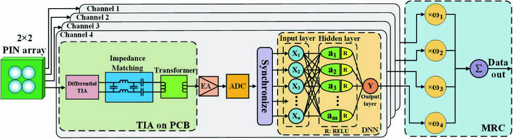
Figure 1.Structure of SIMO-DNN and MRC.
The four independent signals output from the PCB pass the electric amplifier (EA) and analog-digital converter (ADC), respectively. Take one signal for example, after synchronization, it passes a DNN post-equalizer. The DNN structure is presented in Fig. 1, including an input layer, a hidden layer, and an output layer. The hidden layer is fully connected with the input layer and the output layer. Every node in the hidden layer is attached to an activation function, which introduces nonlinear factors to neurons. We choose the rectified linear unit (RELU) as the activation function, which shows better performance in the gradient propagation and computation[11]. The numbers of nodes in the input layer and the hidden layer need to be adjusted according to the training situation.
After the DNN post-equalizer, the four signals need to be transformed into one by diversity combining technology. MRC is the best choice to achieve the optimum BER performance compared to selecting combining and equal gain combining. MRC multiplies the four signals by different coefficients . The determination of is related to the fading coefficient of each branch[13]. Then, the combined signal needs to be further demodulated according to the modulation format. Since the light intensity received by each PIN is different, the SNR of each channel is different. So, we perform DNN post-equalization on the four received signals, respectively, and the network structures of the four DNN equalizers are not the same. If a single DNN post-equalizer is used after MRC, it is difficult to obtain better system performance.
In order to make full use of the frequency resource of the headlight and further the transmission data rate, the bit-loading DMT is a powerful modulation scheme[12,14,15]. It divides the frequency spectrum into multiple communication channels with certain SNRs and assigns an appropriate number of bits to each channel based on the SNR. This process is also called bit allocation. For the purpose of better BER performance, some peak values of the allocated quadrature amplitude modulation (QAM) order are shaved to decrease the step and smooth the transition.
A series of DMT-2QAM pilot signals is first transmitted to measure the SNR of the channel. DMT modulation is a variation of orthogonal frequency division multiplexing (OFDM), which solves the problem of frequency deviations by generating only real signals. The block diagram of the DMT modulation process is shown in Fig. 2. After QAM mapping, serial-to-parallel conversion is performed to obtain frequency-domain signals. This frequency-domain signal is mirror-symmetrical, which is also called Hermitian symmetry. In this way, the data obtained by transforming to the time domain after inverse fast Fourier transform (IFFT) is real data. In order to suppress the inter-symbol interference (ISI), the cyclic prefix (CP) is added to the time-domain data, which is similar to OFDM. In order to increase the overall number of subcarriers, we insert subcarriers of zero in the frequency domain for the convenience of code to achieve frequency-domain compression. It is also called up-sampling and does not affect the performance of DMT.
Figure 2.Experimental setup of the SIMO-DNN VLC for the V2X system.
It is worth noting that the low-frequency response of the headlight is very bad, so we set some low-frequency subcarriers to zero, which is also called zero padding. The number of valid subcarriers can be calculated as where is the total number of valid subcarriers. In our SIMO-DNN VLC for V2X system, ; . The baseband bandwidth can be calculated as where is the sampling rate of the arbitrary waveform generator (AWG), and is the times of up-sampling. The transmission data rate can be calculated as where is the QAM order of the valid subcarrier. In this way, the rate loss caused by zero padding has been excluded from the total transmission rate.
At the receiver end, after serial-to-parallel conversion and removing CP, the signal is transformed into frequency domain by FFT. Then, we removed the zero padding. We optimize the signal with intra-symbol frequency-domain averaging (ISFA) and post-equalizers (zero-forcing is commonly used). Then, the SNR response in the frequency domain can be estimated by means of calculating the error vector magnitude (EVM) of the received signal in every subcarrier. With a desired BER of , the theoretically maximum spectral capacity of every subcarrier can also be obtained from the estimated SNR in their own frequency range[9]. So far, the value of the QAM order (allocated bits) for every subcarrier is determined, which is the closest and smaller integer value relative to the theoretically maximum spectral capacity. In this way, the suitable bit-loading allocation can be deployed for the VLC channel adaptively.
Figure 2 shows the experimental setup of the SIMO-DNN VLC for the V2X system. The bit-loading-DMT signal is generated by an offline MATLAB program and loaded into an AWG (Tektronix, AWG710B). An analog signal is output by the AWG and then passes a hardware pre-equalization circuit to compensate for the channel attenuation for the high-frequency component[10]. The equalized signal is amplified by an EA (Mini-Circuits, 34 dB gain) and then coupled with a direct current (DC) to provide DC bias for the headlight by a bias-tee (Mini-Circuits, ). The optical antenna is fixed on the LED (LUMILEDS, ALITON H1K PnP5) headlight. The signal is transmitted through a free space VLC channel of . At the receiver, after the lens, a blue filter is used to remove yellow fluorescence from white light in order to eliminate the impact of slower fluorescence response. The PIN (Hamamatsu 10784) array outputs four independent signals, and each channel is amplified by a TIA module and an EA (Mini-Circuits, 25 dB gain). The four signals are sampled by a digital sampling oscilloscope (Agilent, MSO9254A) with a 2 GSa/s sampling rate.
The bit-loading allocation at different transmission distances is discussed in Fig. 3. In Figs. 3(a)–3(e), SNR and QAM order of every subcarrier are shown for both SIMO and SISO systems. It is clear that the SIMO system achieved better SNR than the SISO system. Figure 3(f) gives the constellation diagrams with different QAM orders. For the SIMO system, the SNR can support up to 128-QAM in a short distance, while the SISO system can only support 64-QAM. The SNR and QAM orders decrease along with the increase of distance. The commercial LED car light used in this system has a poor frequency response at a certain frequency, which causes the valley of the frequency response. The valley varies for several reasons, including the changes of transmitting power, signal bandwidth, working temperature, etc. In order to achieve high data rate, we selected the optimal working point, and the Fig. 3 shows the actual situation in the experiment.
Figure 3.SNR and QAM order of each subcarrier at transmitting distance of (a) 1 m, (b) 2 m, (c) 3 m, (d) 4 m, and (e) 5 m. (f) Constellation of different QAM orders.
After the determination of the QAM order for every subcarrier, the data rate is also determined. The data rate is calculated as Eq. (3). Figure 4 presents the transmission data rate of both SISO and SIMO systems at different transmission distances. The data rate descends with distances from 1 m to 5 m. For the SIMO system, the data rate exceeds 1 Gb/s at the distance of 4 m, while the data rate of the SISO system exceeds 1 Gb/s at 2 m. At the distance of 1 m, the SIMO system reaches 1.25 Gb/s, while the SISO system reaches 1.07 Gb/s. For the same distance, the data rate of the SIMO system is about 150 Mb/s higher than that of the SISO system. The data rate increase of the SIMO system is due to the SNR gain brought by four-channel MRC.
Figure 4.Achieved data rate of the VLC for the V2X system under different distances.
Then, the bit-loading-DMT signal is transmitted through the VLC channel. After synchronization, the four independent received signals pass the DNN post-equalizers and iterate through a number of input layer nodes, hidden layer nodes, and epochs to select the optimum structure. Figure 5 presents the DNN structures for four channels at point A of Fig. 4. The four structures are not exactly the same, because the SNR of the signal received by each PIN is different. All points in the experiment use this method to select the DNN structures. The number of training samples of each DNN equalizer is 63,360. The four DNN equalizers are performed simultaneously. The total training delay is about 15 s (based on graphics card MX150). The delay can be reduced through hardware upgrades.
Figure 5.DNN structures for four channels at point A in Fig. 4.
Figure 6 presents the mean squared error (MSE) performance versus the number of epochs. As we can see, the training set error drops and saturates after 10 epochs, indicating that there is no underfitting, and the validation set has no error rising, indicating that there is no overfitting. Combining the above two phenomena, the effectiveness and robustness of the neural network are proved.
Figure 6.MSE performance versus number of epochs.
Figure 7 shows the BER performance when varying the voltage peak-peak (Vpp) of the transmitting signal at different transmission distances. It is shown that excessive or too low Vpp both have bad impact on BER performance. Too low of a voltage limits the SNR of the system, while excessive voltage would bring the nonlinear effect of the signal. Furthermore, the optimum Vpp for the system has an upward trend with increasing distance. Moreover, we compared the system performance of using a single DNN equalizer after MRC and MRC after four-channel DNN. Four DNN equalizers bring better system performance. With the increase of Vpp, the effect of DNN is more obvious, which shows that DNN has a suppression effect on nonlinear distortion.
Figure 7.BER performance when varying the Vpp of the transmitting signal under the transmitting distance of (a) 2 m, (b) 3 m, (c) 4 m, and (d) 5 m and measured spectra of the transmitter (Tx) signal, receiver (Rx) signal, and signal after DNN.
The measured spectra of the transmitting signal, received signal, and signal after DNN post-equalizer are shown in the illustration of Fig. 7. The baseband bandwidth is the same as the result of Eq. (2). After transmitting through the VLC channel, the low-frequency portion of the spectra is raised. The DNN post-equalizer can flatten the spectra effectively and achieve suppression of low-frequency noise. Because of zero padding, the low-frequency part of the transmitted signal is zero, while the received signal receives considerable low-frequency noise. Furthermore, with a certain transmission power, the power allocated on each subcarrier increases when we reduce the bandwidth. In order to increase the modulation order of each subcarrier and the total transmission data rate, the bandwidth needs to be reduced when the distance increases. Under the same transmission distance, we traversed the signal bandwidth in the experiment to obtain the maximum transmission rate.
In summary, we proposed and demonstrated an SIMO-DNN VLC for the V2X system. We built an SIMO VLC for the V2X system using a commercial vehicle headlight and a self-designed PIN array receiver. The receiver outputs four independent channels, and each channel goes through a DNN post-equalizer. The MRC of the four channels resulted in higher SNR, which in turn brought about 150 Mb/s data rate gain. By utilizing the bit-loading-DMT modulation scheme, the data rate reached 1.25 Gb/s at the transmission distance of 1 m, while it exceeded 1 Gb/s at 4 m. Furthermore, the investigation of the performance of the SIMO-DNN system showed that DNN post-equalizer brought an anti-nonlinear effect, which brought better BER performance. To the best of our knowledge, it is the first-time demonstration of a beyond 1 Gb/s VLC system employing a commercial car headlight.
References
[1] M. Akanegawa, Y. Tanaka, M. Nakagawa. IEEE Trans. Intell. Transp. Syst., 2, 197(2001).
[2] I. Takai, T. Harada, M. Andoh, K. Yasutomi, K. Kagawa, S. Kawahito. IEEE Photon. J., 6, 7902513(2014).
[3] Y. Liu, Z. Jiang, F. Wang, N. Chi, 509(2018).
[4] N. Chi, Y. J. Zhou, S. Y. Liang, F. Wang, J. Li, Y. Wang. J. Lightwave Technol., 36, 510(2018).
[5] N. Chi, H. Haas, M. Kavehrad, T. D. C. Little, X.-L. Huang. IEEE Wireless Commun., 22, 5(2015).
[6] D. O’Brien, H. L. Minh, L. Zeng, G. Faulkner, K. Lee, D. Jung, Y. J. Oh, E. T. Won. Proc. SPIE, 7091, 709(2008).
[7] N. Chi, F. Hu. Chin. Opt. Lett., 17, 100011(2019).
[8] H. Dong, H. Zhang, K. Lang, B. Yu, M. Yao. Chin. Opt. Lett., 12, 052301(2014).
[9] R. A. Shafik, M. S. Rahman, A. R. Islam, 408(2006).
[10] X. Huang, J. Shi, J. Li, Y. Wang, Y. Wang, N. Chi, 1(2015).
[11] P. Ramachandran, B. Zoph, Q. V. Le(2017).
[12] F. Hu, J. A. Holguin-Lerma, Y. Mao, C. Shen, X. Sun, M. Kong, T. K. Ng, B. S. Ooi, N. Chi. Proc. SPIE, 11307, 113070H(2020).
[13] J. C. William. Mobile Microwave Communication(1974).
[14] Y. Zhou, X. Zhu, F. Hu, J. Shi, F. Wang, P. Zou, J. Liu, F. Jiang, N. Chi. Photon. Res., 7, 1019(2019).
[15] J. Campello, 801(1999).