• Chinese Journal of Lasers
  • Vol. 48, Issue 11, 1101003 (2021)
Quanwei Jiang1、2, Lanping Zhang1、2, Linhui Guo1、2、*, Hao Tan1、2, Hualing Wu1、2, Bo Fu1、2, Nisha Zhang1、2, Fengqun Zhang1、2, Weichuan Du1、2, Deyong Wu1、2, and Songxin Gao1、2
Author Affiliations
  • 1Institute of Applied Electronics, Chinese Academy of Engineering Physics, Mianyang, Sichuan 621900, China
  • 2Key Laboratory of High Energy Laser Science and Technology, Chinese Academy of Engineering Physics, Mianyang, Sichuan, 621900
  • show less
    DOI: 10.3788/CJL202148.1101003 Cite this Article Set citation alerts
    Quanwei Jiang, Lanping Zhang, Linhui Guo, Hao Tan, Hualing Wu, Bo Fu, Nisha Zhang, Fengqun Zhang, Weichuan Du, Deyong Wu, Songxin Gao. Optical Compensation Method for Pigtail Module in High-Brightness Laser Diodes[J]. Chinese Journal of Lasers, 2021, 48(11): 1101003 Copy Citation Text show less
    Diagram of single LD chip package
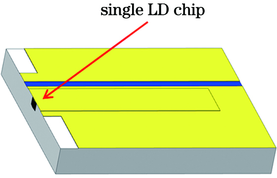
    Fig. 1. Diagram of single LD chip package
    Curves of power and voltage of single cos chip
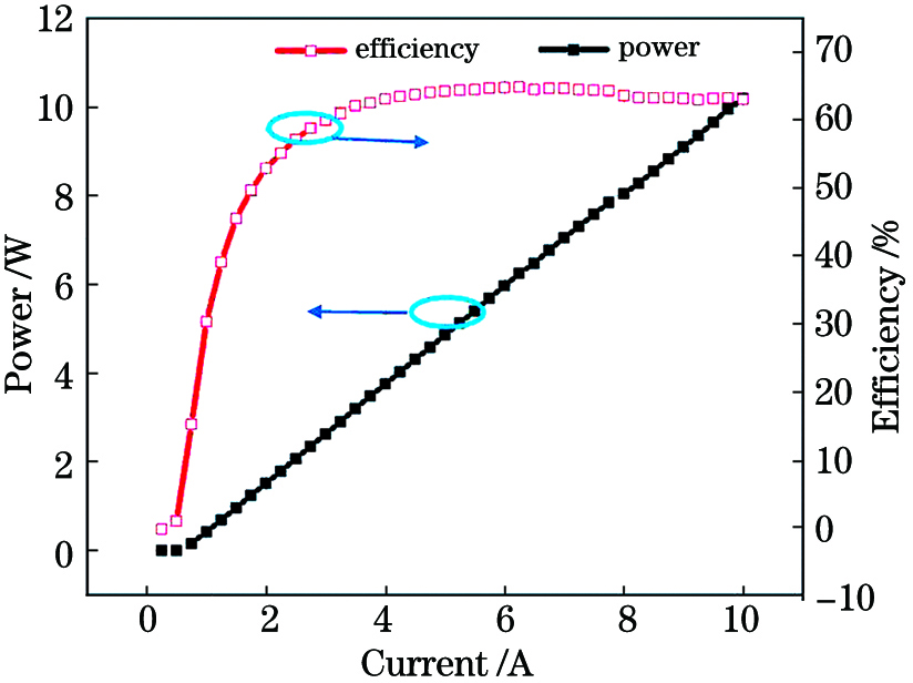
    Fig. 2. Curves of power and voltage of single cos chip
    Curves of divergence angle and wavelength distribution of single cos chip. (a) Curve of divergence angle; (b) wavelength distribution curve
    Fig. 3. Curves of divergence angle and wavelength distribution of single cos chip. (a) Curve of divergence angle; (b) wavelength distribution curve
    Diagrams of slow axis collimation mirrors. (a) Ideal collimation mirror; (b) tilt collimation mirror
    Fig. 4. Diagrams of slow axis collimation mirrors. (a) Ideal collimation mirror; (b) tilt collimation mirror
    Diagram of pigtail module based on 7 steps
    Fig. 5. Diagram of pigtail module based on 7 steps
    Physical picture of slow axis collimation mirror
    Fig. 6. Physical picture of slow axis collimation mirror
    Physical pictures of module. (a) Debug diagram of single chip; (b) debug diagram of multiple single chip
    Fig. 7. Physical pictures of module. (a) Debug diagram of single chip; (b) debug diagram of multiple single chip
    Measured spots of near and far fields. Spot distributions of (a) near field and (b) far field without slow axis collimation mirror; Spot distributions of (c) near field and (d) far field with slow axis collimation mirror
    Fig. 8. Measured spots of near and far fields. Spot distributions of (a) near field and (b) far field without slow axis collimation mirror; Spot distributions of (c) near field and (d) far field with slow axis collimation mirror
    Measured results of pointing error before and after correlation
    Fig. 9. Measured results of pointing error before and after correlation
    Optical designs of LD module. (a) Ray tracing; (b) fiber coupling with large pointing error; (c) spot filled fibers for small and large pointing errors
    Fig. 10. Optical designs of LD module. (a) Ray tracing; (b) fiber coupling with large pointing error; (c) spot filled fibers for small and large pointing errors
    Measured curves of power and efficiency of LD module with tail fiber output
    Fig. 11. Measured curves of power and efficiency of LD module with tail fiber output
    Parameter of PIVValue
    Ith /A0.58
    Von /V1.4
    SE /(W·A-1)1.1
    SE_Max /(W·A-1)1.08
    WPE_Max /%65.26
    I at WPE_Max /A5.5
    P at WPE_Max /W5.48
    Iop /A11
    Pop /W11.13
    V at Iop /V1.64
    WPE at Iop /%61.62
    Table 1. Parameter list of single cos chip
    Experiment No.Thickness of one edge /mmThickness of the other edge /mm
    10.70100.7100
    20.70120.7103
    30.69980.7091
    40.70110.7101
    Table 2. Measured thickness difference of slow axis collimation mirror
    Quanwei Jiang, Lanping Zhang, Linhui Guo, Hao Tan, Hualing Wu, Bo Fu, Nisha Zhang, Fengqun Zhang, Weichuan Du, Deyong Wu, Songxin Gao. Optical Compensation Method for Pigtail Module in High-Brightness Laser Diodes[J]. Chinese Journal of Lasers, 2021, 48(11): 1101003
    Download Citation