This Letter investigates the performance of the two-way multi-hop system for underwater optical wireless communications. With the decode-and-forward (DF) relaying, the two-way multi-hop system is modeled, where the effects of absorption, scattering, and oceanic turbulence are all taken into account. An exact closed-form expression for outage probability is derived under the assumption that the oceanic turbulence obeys a log-normal distribution. Numerical results demonstrate the impacts of various parameters on the outage performance and indicate that the two-way multi-hop system significantly improves the performance in comparison to both the one-way multi-hop system and the two-way two-hop system.
Underwater optical wireless communication (UOWC) has attracted widespread attention since it possesses the advantages of large transmission bandwidth, high data rate, ultralow propagation delay, and high security[1–3]. The channel and system modeling for UOWC has been amply studied. The channel loss can be characterized by the Beer–Lambert law[3] and beam spread function[4], whereas the oceanic turbulence can be typically modeled as log-normal[5,6], gamma-gamma[7], and exponential generalized gamma distributions[8]. However, the UOWC suffers from several challenges, such as limited communication range and large path loss. Relay-assisted communications can be employed to overcome these shortcomings.
Several notable researches have been explored to analyze the performance on one-way (unidirection) relay-assisted systems for the UOWC. The performance of multi-hop networks over log-normal turbulent channels[5,6] and gamma-gamma turbulent channels[7] has been evaluated. The performance of amplify-and-forward (AF) relaying and decode-and-forward (DF) relaying for underwater networks has been studied and compared[9]. The connectivity of the multi-hop underwater network and its impact on localization are analyzed[10], where the network is modeled as randomly scaled sector graphs. These relay-assisted systems commonly operate in half-duplex mode, since the severe interference between transmitted signals and incoming weak received signals in full-duplex mode cannot be omitted and is difficult to be eliminated[11,12]. For one-way half-duplex relay systems, two terminals assisted by a single relay require four time slots to accomplish information exchange, which may lead to the loss of spectral efficiency. To reduce such loss, two-way relay schemes can be adopted, where two terminals only require two time slots to exchange their information and achieve full-rate transmission.
There have been sporadic studies on two-way relay systems for wireless optical communications. An orthogonalize-and-forward relaying scheme for two-way multi-user scenarios is presented[12], which can significantly decrease the spectral loss. The performance of the two-way system for a mixed radio frequency/free space optical (RF/FSO) network is studied[13]. For two-way free space optical (FSO) networks, a closed-form expression of system outage and error probability is derived over gamma-gamma atmospheric turbulence[14,15], whereas an analytic expression of end-to-end signal-to-noise ratio (SNR) is solved over Malaga atmospheric turbulence[16]. Three algorithms of multi-user scheduling applied to two-way networks are proposed[17], including absolute SNR, normalized SNR, and selective multi-user diversity scheduling algorithms.
Sign up for Chinese Optics Letters TOC. Get the latest issue of Chinese Optics Letters delivered right to you!Sign up now
The abovementioned studies focus on the two-way relay systems for FSO networks over atmospheric channels. These achievements cannot be directly applied in the UOWC, since the underwater channel suffers from the negative effects induced by absorption and scattering in addition to turbulence. Moreover, most existing studies only consider the two-way system with single relay and two hops. As the transmission range is extremely limited for the UOWC, serial relay systems with multiple hops may be more practical. Consequently, it is necessary to explore the characteristics of two-way multi-hop systems, where two terminals assisted by multiple relays exchange information concurrently. Such systems can improve the spectral efficiency and extend the end-to-end transmission distance.
In this Letter, we investigate the performance of the two-way multi-hop system for UOWC. Specifically, the two-way multi-hop system based on DF relaying is modeled, with consideration of the effects of absorption, scattering, and oceanic turbulence. A closed-form expression for outage probability is derived over log-normal oceanic turbulence channels. Numerical results demonstrate the effects of various parameters, including the number and location of relays, the type of ocean water, the type of light wave (plane or spherical wave), and the power allocation on the system performance.
The aggregated channel model that comprises the turbulence-induced fading and the path loss incurred by absorption and scattering is considered in this work. The channel gain between node and node can be given as[6]where denotes the turbulence-induced fading amplitude, and denotes the path loss. The path loss for line-of-sight links can be expressed as[18]where and are the optical efficiency of the transmitter and the receiver, respectively. represents the aperture area of the receiver, is the inclination angle between the transmitter and the receiver, is the transmission distance from node to node , is the beam divergence angle of the transmitter, and denotes the attenuation coefficient that is a combination of absorption coefficient and scattering coefficient . The typical values of measured at are summarized in Table 1[18].
Water Types
a(λ)(m−1)
b(λ)(m−1)
c(λ)(m−1)
Pure sea water
0.053
0.003
0.056
Clear ocean water
0.114
0.037
0.151
Coastal ocean water
0.179
0.219
0.398
Table 1. Typical Values of Attenuation Coefficients for Three Types of Ocean Water[18]
To characterize the turbulence effects, the turbulence-induced fading amplitude is modeled by log-normal distribution that is applicable to weak turbulence conditions. The probability density function of can be formulated as[5,6]where is the fading log-amplitude modeled by Gaussian distribution with the mean of and the variance of . The amplitude is supposed to be normalized to conserve the average power, which yields that is calculated in terms of . The variance is related to the scintillation index , which can be given as[6,19]
The scintillation index, depending on the wave number, the scalar spatial frequency, the transmission distance, and the power spectrum of turbulent fluctuations, can be separately discussed in terms of plane and spherical light waves[19].
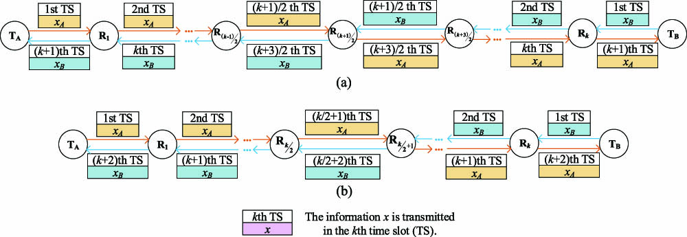
The two-way multi-hop system consists of two terminals and relays, which is depicted in Fig. 1. All nodes including terminals and relays are equipped with multiple transceivers and capable of half-duplex communication. The intensity modulation with direct detection (IM/DD) is employed in all nodes. For UOWC, since the transmission distance of one hop is limited, the propagation delay (computed as the ratio between the transmission distance and the light wave propagation speed over ocean water) is extremely small and can be omitted compared to the transmission delay that is equal to the ratio between the packet size and the data rate. The time slot can be set in terms of the packet size. In this case, the two-way multi-hop system can be discussed according to two scenarios, where the numbers of relays are odd [see Fig. 1(a)] and even [see Fig. 1(b)], respectively. For the scenario in Fig. 1(a), the information from two terminals arrives at the middle relay () at the same time, and then can exchange the information and concurrently convey it towards two terminals. For the scenario in Fig. 1(b), since relays cannot listen and transmit simultaneously, and have to exchange the information in two time slots.
Figure 1.Multi-hop two-way systems: (a) Scenario 1 with an odd number of relays, (b) Scenario 2 with an even number of relays.
It is assumed that the channel state information (CSI) is available at each node. Based on the CSI, nodes select the next-hop node that has the best performance (such as the highest instantaneous SNR and the lowest outage probability) to complete information transmission. There have been several notable relaying techniques, such as AF relaying, DF relaying, and bit-detect-and-forward (BDF) relaying. AF relaying may accumulatively propagate noise along the transmission path, whereas BDF relaying may forward the incorrect bit since it does not employ any error correcting approach[3]. DF relaying adopts error detection methods to guarantee the correctness of signals and can restrict the noise propagation, which improves the system performance. DF relaying is considered in this work, and the process of the information delivery is elaborated as follows.
In the first time slot, two terminals ( and ) transmit the information to their neighboring relays ( and ) simultaneously. The received information at and from the two terminals can be expressed as where is the responsivity of the photodetector, is the quantum efficiency of the photodetector, is the electron charge, is Planck’s constant, and is the frequency of the optical source. and denote the transmitted powers of pointing to and pointing to , respectively. and denote the channel gains of the channel from to and the channel from to , respectively. and denote the transmitted information from and , respectively. and denote the received noise at and , respectively.
In the second slot, and receive the information from and , and decode the information. Forward error correction (FEC) is assumed to be employed to guarantee the correctness of signals. For brevity, the decoded information is also represented by and . After decoding the received information, recodes and forwards it to the next-hop node () towards (defined as the forward transmission direction), and concurrently, recodes and forwards it to the next-hop node () towards (defined as the backward transmission direction). The received information at and can be given by where and denote the transmitted powers of pointing to and pointing to , respectively. and denote the channel gains of the link from to and the link from to , respectively. and denote the received noise at and , respectively.
The information is simultaneously transmitted via relays for two transmission directions to exchange information. In the last slot, the received information at and can be expressed as where and denote the transmitted powers of pointing to and pointing to , respectively. and denote the channel gains of the link from to and the link from to , respectively. and denote the received noise at and , respectively. It can be inferred that completing the information exchange requires () or () time slots in ()-hop networks for two-way relay systems, instead of time slots for one-way relay systems.
The outage probability of the two-way multi-hop system for UOWC is derived to assess the system performance. It is known that the performance of DF relaying depends on the worst links[11]. Therefore, the SNR for the forward transmission direction and the backward transmission direction can be calculated by where and represent the instantaneous SNR in forward and backward transmission directions, respectively. and are defined as[6,18]where and are the variances of the noise at node of the forward direction and node of the backward direction. In general, the noises in the UOWC system include background noise, dark current noise, shot noise, and thermal noise. Such noises are additive and independent of each other, and hence, they can be assumed as independent and identically distributed (i.i.d) and modeled as additive white Gaussian noise (AWGN) with zero mean. Since the signal shot noise that depends on the incoming optical signal power can be omitted compared with the other noise components, such noise is signal-independent. The calculation of total noises in the UOWC system is detailed in the research by Jaruwatanadilok[20], which is related to the bandwidth and water depth.
For the two-way relay system, the outage occurs when any of the transmission directions (forward and backward ) fails. The outage probability can be expressed as where is the SNR threshold. can be obtained by substituting Eq. (11) and Eq. (12) into Eq. (14) as
Inserting Eq. (13) into Eq. (15) yields
Since obeys log-normal distribution, is also a log-normal random variable with the mean and variance as and , respectively. This principle is also applicable to . Therefore, the outage probability can be computed as where is the function given as
To evaluate the performance of the two-way multi-hop system over log-normal turbulence channels, we carry out extensive numerical studies, where , , , and are taken, and the water depth is 50 m. Other parameter settings regarding the scintillation index (which determines the turbulence effects for UOWC) and underwater noise are detailed in the researches by Jamali et al.[6] and Korotkova et al.[19], and the research by Jaruwatanadilok[20], respectively.
Figures 2 and 3 depict the outage probability with respect to the transmission distance and the total power transmitted with non-relay (direct) communications and one to four relay-assisted communications. In these numerical results, it is assumed that successive nodes are equidistant along the link between two terminals, and the transmitted powers of all nodes including terminals and relays are the same.
Figure 2.Outage probability versus transmission distance for two-way multi-hop systems (a) with clear ocean water and (b) with pure sea water .
In Fig. 2, the total transmitted power (denoted as ) is set to 20 dBm, and hence, the transmitted power of each node for single transmission is , where denotes the number of relays. For clear ocean water, it can be observed that the maximal distances that can be reached with non-relay and one to four relay-assisted communications are approximately 19 m, 32 m, 44 m, 55 m, and 65 m at the outage probability of for a plane light wave, whereas the distances for a spherical light wave are approximately 20 m, 35 m, 50 m, 62 m, and 73 m. For pure sea water, the maximal distances are much longer than those for clear ocean water, which are approximately 29 m, 48 m, 66 m, 82 m, and 96 m for a plane wave and 33 m, 55 m, 72 m, 92 m, and 106 m for a spherical wave. It can be concluded that a spherical light wave suffers from less negative effects induced by turbulence than a plane light wave. Additionally, employing relays can significantly extend the transmission range for UOWC, where the maximal distance of the scheme with four relays can be increased by 73 m compared with that of the non-relay scheme under pure sea water and a spherical light wave.
In Fig. 3, the transmission distance (representing the distance between and ) is set to 150 m, and hence, the distance between neighboring nodes is . For clear ocean water, the required total transmitted powers with non-relay and one to four relay-assisted communications are approximately 140 dBm, 81 dBm, 59 dBm, 48 dBm, and 41 dBm with the outage probability of for a plane wave, whereas the powers for a spherical wave are approximately 136 dBm, 76 dBm, 55 dBm, 45 dBm, and 38 dBm. Due to less attenuation incurred by absorption and scattering, the required total transmitted powers over pure sea water are much less than those in clear ocean water, which are approximately 78 dBm, 50 dBm, 38 dBm, 33 dBm, and 28 dBm for a plane wave and approximately 74 dBm, 45 dBm, 35 dBm, 29 dBm, and 26 dBm for a spherical wave. Numerical results demonstrate that more transmitted power can be saved by utilizing relays for assisting information transmission. In contrast to the non-relay scheme, the scheme with four relays can save the transmitted power by 99 dB under clear ocean water and a plane light wave.
To assess the spectral efficiency, we investigate the sum rate of the proposed two-way multi-hop system, where the sum rate is defined as the summation of the achievable rate of two transmission directions including forward and backward [12,16]. The sum rates of one-way and two-way relay systems with one to four relays are shown in Fig. 4. In comparison to one-way relay system, a two-way relay system invariably shows better performance in sum rate, which indicates that the two-way relay system improves the spectral efficiency. It is noted that the sum rate is decreased with the increase of the number of relays. Further investigations are required to offer a good compromise between the sum rate and the transmission range, which will not be elaborated in this Letter.
Figure 4.Sum rates of one-way and two-way systems (a) with single relay, (b) with two relays, (c) with three relays, and (d) with four relays.
It is known that relay location and power allocation greatly affect the performance of relay-assisted systems. To assess these effects, we demonstrate the comparisons of various relay locations and various power allocations in two-hop two-way systems under a plane light wave.
The impact of relay locations on outage probability is depicted in Fig. 5, in which the distance between two terminals is set to 30 m, and the transmitted power of each node is the same. denotes the transmission distance between and the relay , and denotes the transmission distance between and . It can be observed that the system shows the best performance when the relay is in the middle of these two terminals (denoted by blue lines). The power can be saved by up to 17 dB when comparing with under coastal ocean water.
Figure 5.Outage probability of two-hop two-way systems with three types of water and three relay locations.
The impact of power allocation on the outage probability is shown in Fig. 6 with . Since the channel losses from to and from to are identical, we assume that and , which are denoted by and in Fig. 6, respectively. It can be observed that the proportional power allocation (denoted by blue, red, and green dashed lines) shows better performance with up to 3 dB power saving than equal power allocation while comparing dashed lines to solid lines and dotted lines for each color.
Figure 6.Outage probability of two-hop two-way systems with equal power allocation and proportional power allocation under clear ocean water.
In conclusion, a two-way multi-hop transmission scheme for the UOWC is explored in this Letter. We model the two-way multi-hop system based on DF relaying while considering the effects of absorption, scattering, and oceanic turbulence. For the considered system, an exact closed-form expression for outage probability is derived under the log-normal turbulent channel. Numerical results demonstrate the impacts of various factors on the outage performance, which indicates that the performance of the two-way multi-hop system can be significantly improved compared to both the one-way multi-hop system and the two-way two-hop system.