• Chinese Optics Letters
  • Vol. 15, Issue 8, 082401 (2017)
Le Yu1、2, Xiao Xiong1、2, Di Liu1、2, Lantian Feng1、2, Ming Li1、2, Linjun Wang3, Guoping Guo1、2, Guangcan Guo1、2, and Xifeng Ren1、2、*
Author Affiliations
  • 1Key Laboratory of Quantum Information, CAS, University of Science and Technology of China, Hefei, 230026, China
  • 2Synergetic Innovation Center of Quantum Information & Quantum Physics, University of Science and Technology of China, Hefei, 230026, China
  • 3Center for Micro- and Nanoscale Research and Fabrication, University of Science and Technology of China, Hefei, 230026, China
  • show less
    DOI: 10.3788/COL201715.082401 Cite this Article Set citation alerts
    Le Yu, Xiao Xiong, Di Liu, Lantian Feng, Ming Li, Linjun Wang, Guoping Guo, Guangcan Guo, Xifeng Ren. Multiple directional enhanced light source through a periodic metal grating structure[J]. Chinese Optics Letters, 2017, 15(8): 082401 Copy Citation Text show less
    (a) Schematic description of the experimental setup. (b) The SEM image of the metal grating sample; the period of the grating is about 450 nm. (c) Luminescence spectrum of QDs.
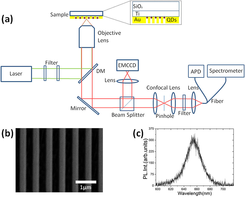
    Fig. 1. (a) Schematic description of the experimental setup. (b) The SEM image of the metal grating sample; the period of the grating is about 450 nm. (c) Luminescence spectrum of QDs.
    (Color online) (a) The back focal plane image of the luminescence in grating sample A. (b) Phase relation for wave vectors of emissions and SPPs. k0 represent the actual direction of the emission light, and p is the grating period. (c) Schematic image of the Fourier plane. The black circle represents the actual view field, which we can observe from the back focal plane.
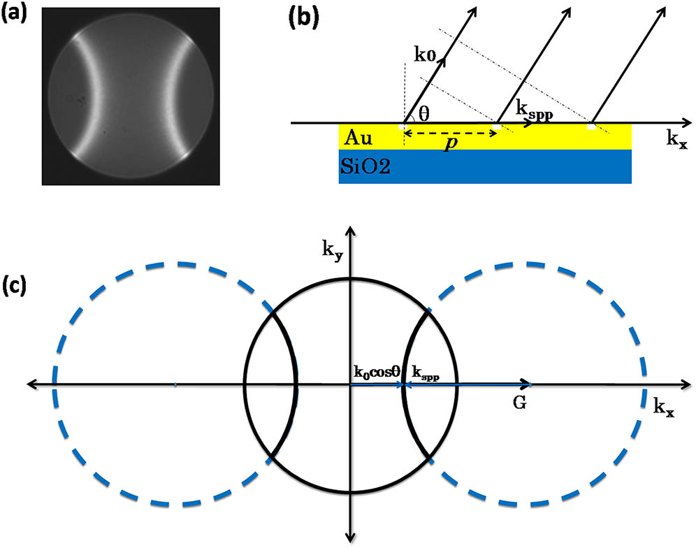
    Fig. 2. (Color online) (a) The back focal plane image of the luminescence in grating sample A. (b) Phase relation for wave vectors of emissions and SPPs. k0 represent the actual direction of the emission light, and p is the grating period. (c) Schematic image of the Fourier plane. The black circle represents the actual view field, which we can observe from the back focal plane.
    (a)–(e) The SEM images of five samples, in which the Au gratings are etched through. The grating constants are (a) 450, (b) 500, (c) 650, (d) 850, and (e) 1050 nm, respectively. (f)–(j) The back focal plane images of the luminescence for the corresponding grating samples. (k)–(o) The back focal plane images of the luminescence for the corresponding grating samples, which have the same grating constant but are not etched through.
    Fig. 3. (a)–(e) The SEM images of five samples, in which the Au gratings are etched through. The grating constants are (a) 450, (b) 500, (c) 650, (d) 850, and (e) 1050 nm, respectively. (f)–(j) The back focal plane images of the luminescence for the corresponding grating samples. (k)–(o) The back focal plane images of the luminescence for the corresponding grating samples, which have the same grating constant but are not etched through.
    (Color online) (a) The lifetime of QDs on bare silica substrate, where t=11.66 ns. (b) The lifetime of QDs on the Au grating, where t=3.28 ns.
    Fig. 4. (Color online) (a) The lifetime of QDs on bare silica substrate, where t=11.66ns. (b) The lifetime of QDs on the Au grating, where t=3.28ns.
     θ
    Samplen=1n=2n=3
    A(450 nm)66.0016°
    B(500 nm)74.8614°
    C(650 nm)87.6415°14.8635°
    D(850 nm)73.8438°60.5061°
    E(1050 nm)64.8471°78.5347°34.6557°
    Table 1. Directional Emission Angles for the Five Samples
    Le Yu, Xiao Xiong, Di Liu, Lantian Feng, Ming Li, Linjun Wang, Guoping Guo, Guangcan Guo, Xifeng Ren. Multiple directional enhanced light source through a periodic metal grating structure[J]. Chinese Optics Letters, 2017, 15(8): 082401
    Download Citation