
Siyuan Dong, Pariksheet Nanda, Kaikai Guo, Jun Liao, and Guoan Zheng. Incoherent Fourier ptychographic photography using structured light[J]. Photonics Research, 2015, 3(1): 19
- Photonics Research
- Vol. 3, Issue 1, 19 (2015)
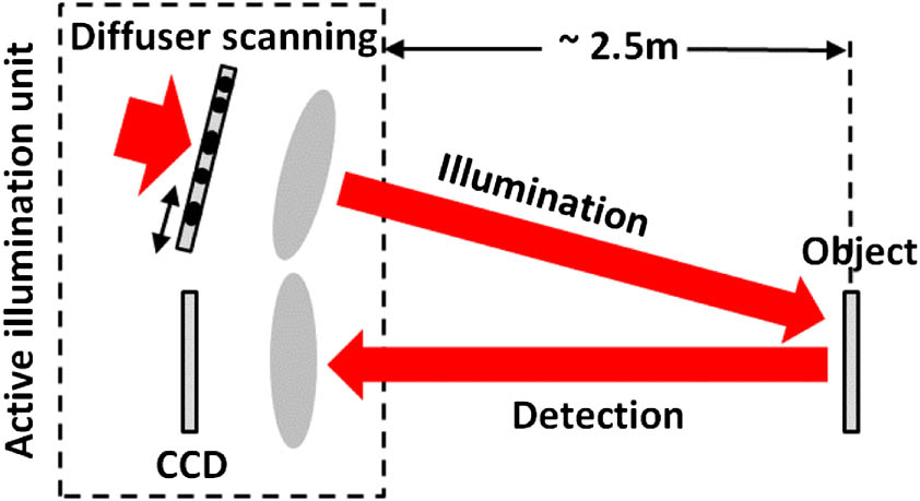
Fig. 1. Schematic of the FPP setup. In the illumination path, a diffused LED was used for incoherent illumination (red arrow on the left). A semitransparent diffuser was placed in front of the diffused LED, and its image was projected onto the object. In the detection path, a photographic lens (Nikon, 50 mm) was used to collect the reflected light from the object.
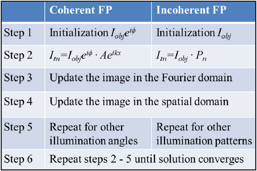
Fig. 2. Recovery procedures of the coherent and incoherent FP approaches. For the case of incoherent FP, the updating processes in steps 3 and 4 can be expressed as Eqs. (1 3 ).
Fig. 3. Imaging performance of the reported FPP platform. (a) The reference image captured under uniform illumination, (b1) the captured raw image under pattern illumination, (b2) the recovered image using 100 raw images, (b3) the recovered illumination pattern, (b4) line traces of (a) and (b2). Also refer to Media 1 .
Fig. 4. Image reconstruction using different numbers of raw images. The solution converges with the 16 raw images. We used 15–20 loops in this experiment.
Fig. 5. Demonstration of the reported platform for different objects: a dollar bill, a quick response code, and an insect. (a1)–(c1) The reference images under uniform illumination, (a2)–(c2) the recovered images using the reported platform. We used 100 raw images and 15 loops for the reconstruction. Also refer to Media 2 .
Fig. 6. Imaging a color object using the reported platform. (a1)–(a3) Reference images using uniform R/G/B illumination, (b) combined reference color image, (c1)–(c3) recovered super-resolution images using the reported platform, (d) combined super-resolution color image.

Set citation alerts for the article
Please enter your email address
© Copyright 2018-2021 | Chinese Laser Press. All Rights Reserved 沪ICP备15018463号-20