Based on a single-channel laser self-mixing interferometer, we present a new simultaneous measurement of the vibration amplitude and the rotation angle of objects that both affect the power spectrum containing two peaks of the interferometer signals. The fitted results indicate that the curve of the peak frequency versus the vibration amplitude follows a linear distribution, and the curve of the difference of the two-peak power values versus the angle follows a Gaussian distribution. A vibration amplitude with an error less than 3.0% and a rotation angle with an error less than 11.7% are calculated from the fitted results.
Laser self-mixing (LSM) interferometry is an advanced, simple, and non-contact sensing technology based on the laser modulation phenomenon that occurs when light is reflected by external objects and re-enters the laser cavity, resulting in LSM interference. LSM interferometry is used for measurements of the vibration[1,2], displacement[3], velocity[4], and relative angle[5] of objects, and to resolve chaos outputs in lasers[6].
Real-time measurements of multiple objects or dimensional information, which is important in the fields of optical collimation, micro-electromechanical systems, and precision machining, have been achieved by means of multiple-channel interferometry[1,7,8]. However, compared with multiple-channel interferometry, single-channel interferometry is not only simpler, but also costs less. The respective measurement of the magnitude of the vibration or the relative angle of an object based on single-channel interferometry has been reported. Giuliani et al.[4] reported vibration measurements using LSM fringe counting and power spectrum analysis; however, the resolution of the conventional measurement was fixed as half of the laser wavelength. Zhong et al.[5] reported angle measurements based on LSM interferometry using the detection of the fringe amplitude; however, the fringe envelope might cause false experimental detection.
We present a fiber-based single-channel LSM interferometer that demonstrates the capability of simultaneously measuring both the vibration amplitude and the relative angle of a plane mirror affixed to an audio speaker. We report the theoretical principle of the measurement based on LSM interferometry using the dual optical feedback effect in the weak regime. The characteristics of interferometer signals with respect to both the vibration amplitude and relative angle are obtained experimentally.
Sign up for Chinese Optics Letters TOC. Get the latest issue of Chinese Optics Letters delivered right to you!Sign up now
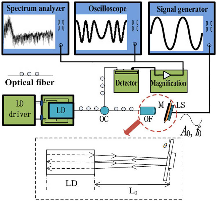
A schematic of the experimental setup is shown in Fig. 1, where a mirror (M) is affixed to a speaker (LS) positioned directly in the laser path at a distance representative of the focal length of the optical fiber focuser (OF) at a small angle , as measured perpendicularly with respect to the incident laser light. Backscattered light re-enters the laser diode, and a portion of this is reemitted by the laser diode, is backscattered, and re-enters the laser diode for a second time. Liu et al.[9] has described the LSM effect considering both the first and second feedback lights. In the weak feedback regime, the laser output power with dual optical feedback is given as
Figure 1.Schematic of the experimental setup: optical fiber circulator (OC), optical fiber focuser (OF), loudspeaker (LS), laser diode (LD), and mirror (M).
Here, the subscripts denote the first and second feedback events, is the laser output power without modulation, denotes the modulation coefficient, and denotes the phase shifting where is the laser wavelength and is the optical path length. The optical paths can be given as where is the external cavity length. As shown in Fig. 1, the mirror vibrates according to a sine signal of the amplitude and frequency applied to the speaker, so where denotes time. Equation (1) can be given as can be rewritten as follows according to a Fourier series: where denotes the phase of the cos term of Eq. (4).The Fourier transform is given in terms of frequency as
For the experimental setup shown in Fig. 1, the light source is a distributed feedback laser with an optical fiber end, emitting 30 mW at 1550 nm on a single mode, controlled by an LD driver. The laser is split into two parts by the optical fiber circulator (OC), where one part, which irradiates the mirror, is used for generating the LSM signal, and the other part is coupled with the detector used for monitoring the LSM signal. The signal is observed after magnification. A rotary stage with a precision of 0.003° is used for adjusting . , the free external cavity length, is set to 1 cm (the focal length of the optical fiber focuser), so that an LSM signal with dual optical feedback effect is obtained clearly. There is only dual optical feedback because of two reasons: the longer time feedback light is too weak to detect after multiple reflections and transmissions, and it may escape from the laser facet as the mirror is tilted[9]. The waveform and power spectrum are obtained by a digital oscilloscope and a spectrum analyzer, respectively.
The abscissa axis of the oscilloscope denotes time (), and the ordinate axis denotes the power (). The abscissa axis of the spectrum analyzer denotes the frequency , and the ordinate axis denotes the power (dB), where the resolution is 15 Hz, the reference level is , and the bandwidth is 4 kHz.
Figure 2(a) shows a typical LSM signal waveform obtained experimentally for , , and . The waveform consists of fringes where every fringe contains a main peak and a secondary peak . Due to the dual optical feedback effect, transforms according to the value of , while and transform according to the value of . To characterize the waveform transformation precisely, the waveform is converted into a power spectrum. Figure 2(b) shows a typical power spectrum containing two spectrum peaks for , where and are the peak power and frequency. It is noted that the power spectrum always contains two peaks, where .
Figure 2.Typical LSM signal: (a) waveform, and (b) power spectrum.
Considering the power spectra obtained while varying , we examine and while varying from 0 to by adjusting the signal generator, and keeping and . We find that all power spectra include equivalent , but exhibit values of that vary according to . This indicates that only affects .
The experimental results in Fig. 3 show that and both approximately increase linearly with increasing . The data plotted in Figs. 3(a) and 3(b) were fitted with linear equations, and the fitted results are given as Eqs. (7)–(9), where can be calculated if or is obtained. The error associated with the calculation is given as , where is the calculated vibration amplitude. The slope of Eq. (9) is nearly twice that of Eq. (8), which is consistent with the analysis regarding optical lengths given by Eq. (2). According to a previous study[9], the resolution of an interferometer employing dual optical feedback is a quarter of the wavelength, which is twice that of conventional interferometers.
Figure 3.Linear fitting of (a) number of fringes versus the vibration amplitude , and (b) peak frequency for versus vibration amplitude .
Considering the power spectra obtained while varying , we find that all power spectra include equivalent (i.e., and , where ), but exhibit values of that vary according to . This indicates that only affects , while and are both unchanged, so can be obtained at fixed . To consider the effect of on , we varied within a narrow interval from 0.930° to 1.140° by adjusting the rotary stage slightly while keeping and . The results are plotted in Fig. 4. Because and both change, is used for characterizing the waveform transformation. The value of in Fig. 5 is the average result, and .
Figure 4.Experimental waveforms for various values of : (a) 0.990°, (b) 1.020°, and (c) 1.029°.
The experimental results in Fig. 5 show that first increases to a maximum value and then decreases as the rotation angle increases from 0.930° to 1.140°. The curve fitting is carried out using several fitting expressions. The error of curve fitting with the Gaussian expression is least; therefore, versus follows a Gaussian distribution approximately. The fitted results are shown as Eq. (10), with which could be calculated if is obtained experimentally. The error of the calculation is given as , where is the calculated angle. The range of the angle measurement is limited by the emergent aperture of the laser. Under a larger range of rotation angles, there is no dual optical feedback, because the second feedback light may escape from the laser facet after two reflections. is the minimum value when or .
A single-channel LSM interferometer is constructed that simultaneously measures the magnitude of the vibration of an object and the angle of its position relative to the incident beam. The working principles of the interferometer are discussed from a theoretical point of view, and experimentally tested using a mirror affixed to a speaker driven with a sine signal of some amplitude and frequency and at some adjustable angle relative to the incident beam. The experimental waveform and power spectrum of the interferometer signal are affected by the mirror’s vibration amplitude and the angle of the mirror relative to the incident beam, both of which can be measured from the dual-peaked power spectrum. It is demonstrated that the peak frequency is only affected by the vibration amplitude, and the fitted results indicate that the curve of the peak frequency versus the vibration amplitude follows a linear distribution, whereas the curve of the difference of the two peak power values versus the angle follows a Gaussian distribution. The curve fitting provides a vibration amplitude with an error less than 3.0% and a rotation angle over a range of 0.075°, with an error less than 11.7%. The resolution of the vibration measurement is twice that of many conventional measurement methods due to the dual optical feedback effect. The influence of the envelope waveform is mitigated because the difference of two peak power values is used for the angle measurement. The proposed method is expected to be applicable to precision measurements.