
Yan Li, Xiaojin Huang, Shuxin Liu, Haowen Liang, Yuye Ling, Yikai Su. Metasurfaces for near-eye display applications[J]. Opto-Electronic Science, 2023, 2(8): 230025-1
- Opto-Electronic Science
- Vol. 2, Issue 8, 230025-1 (2023)
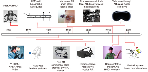
Fig. 1. Roadmap of near-eye display development. First AR Head-Mounted Display (HMD) prototype, developed by Ivan Sutherland in 1968. Figure reproduced from ref.16, under a Creative Commons Attribution 4.0 International. VR HMD, National Aeronautics and Space Administration (NASA) Ames VIEW. Figure reproduced from ref.17, National Aeronautics and Space Administration. HMDs based on waveguide devices and freeform surfaces. First AR commercial glass-product, SV-6 PC viewer, developed by MicroOptical in 2003. Figure reproduced from ref.20, the MicroOptical Corporation. Monocular optical see-through smart glass, Google Glass, developed by Google in 2012. Figure reproduced from ref.21, Wikipedia. Representative modern VR HMD, Oculus Rift. Figure reproduced from ref.22, Wikipedia. Representative modern AR HMD, Microsoft HoloLens 1, based on optical waveguides in 2015. Figure reproduced from ref.23, Wikipedia. First commercial dual-focal AR display device, Magic Leap one, released by Magic Leap in 2018. Figure reproduced from ref.24, Wikipedia. First AR system based on a metasurface device proposed by Lee et al. in 2018. Figure reproduced from ref.25, Nature Publishing Group, under a Creative Commons Attribution 4.0 International. Video-see-through AR glass, Apple Vision Pro, developed by Apple in 2023. Figure reproduced from ref.26, Apple.
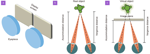
Fig. 2. (a ) VR display optical schematic diagram. (b ) Consistent accommodation and vergence distances when observing the real-world scene. (c ) Mismatch between accommodation and vergence distances when viewing with a stereoscopic 3D display.
Fig. 3. Schematics of AR display architectures based on (a ) a half mirror/BS combiner, (b ) birdbath optics, (c ) freeform prisms, and (d ) a waveguide with grating couplers. (e ) Schematic diagram of a video see-through AR display.
Fig. 4. (a ) Schematic of a multizone RGB-achromatic metalens. (b ) Scanning electron microscope (SEM) image of a 2-mm-diameter achromatic metalens with NA=0.7. (c ) Schematic of the VR mode employing the achromatic metalens. (d , e ) VR display results with a 3D effect. (f , g ) Full-color VR display results. The scale bar is 20 μm in (d–g). Figure reproduced with permission from ref.102, American Association for the Advancement of Science.
Fig. 5. (a ) Photograph of a 1-cm-diameter RGB-achromatic metalens. The inset is the SEM image of the nanostructures used in the metalens and the scale bar is 500 nm. (b ) Measured focal intensity distribution in the XZ plane at RGB wavelengths of the achromatic metalens. (c ) Photograph of VR imaging setup employing the achromatic metalens. (d –f ) Binary VR imaging results at RGB wavelengths. (g ) Simulated full-color VR imaging result by combining RGB image channels shown in (d-f). The scale bar is 100 μm in (d-g). Figure reproduced from ref.103, Nature Publishing Group, under a Creative Commons Attribution 4.0 International License.
Fig. 6. Schematic of the mass production of metalenses using an ArF immersion scanner. ACL, amorphous carbon layer.
Fig. 7. (a ) Schematic of a see-through AR display system based on a chromatic transmissive metalens. (b ) SEM image of the see-through metalens and (c ) full-color AR image. (d ) Schematic of a VR display system employing a 1-cm-diameter RGB-achromatic metalens and (e -g ) AR display results. LCP, left-handed circular polarizer; RCP, right-handed circular polarizer; ML, metalens; DMs, dichroic mirrors. Figure reproduced with permission from: (a–c) ref.25, Nature Publishing Group, under a Creative Commons Attribution 4.0 International License; (d–g) ref.102, American Association for the Advancement of Science.
Fig. 8. (a ) Schematic of a polarization-dependent metagrating-based out-coupler. (b ) Schematic of a large-FOV, full-color AR display prototype based on a single-layer metasurface optical element, (c ) SEM image of an optimized full-color metasurface element, and (d ) AR display result. (e ) Schematic of an on-chip metasystem for AR display. (f ) Schematic of the inverse-designed metagrating architecture with wavelength-demultiplexing functionality. (g ) Simulated in-coupling efficiency of the metagrating at opposite ports in the visible regime. (h ) AR display results. The scale bar is 5 μm in (c), and the inset in (d) is the original image. Figure reproduced with permission from: (b–d) ref.114, Nature Publishing Group, under a Creative Commons Attribution 4.0 International License; (e–h) ref.119, American Chemical Society.
Fig. 9. (a ) Schematic of the optical behavior of a see-through refective metalens-visor. (b ) Schematic of a near-eye AR display system based on the metalens-visor. (c ) Measured focal spot intensity profile of the fabricated metalens at the illumination wavelength of 633 nm. (d ) Simulated and measured transmittance spectra of the metalens. (e ) SEM image of the fabricated metalens. The scale bar is 400 nm. (f , g ) Demonstration of multi-color AR imaging. Figure reproduced from with permission ref.122, Springer Nature, under a Creative Commons Attribution 4.0 International License.
Fig. 10. (a ) Schematics of 14 kinds of center-symmetrical nanostructures used in an RGB achromatic trans-reflective metalens. (b ) Comparison of the ideal phase profile and the matched phase of the metalens at RGB wavelengths. Simulation focal intensity distribution in the XZ plane at RGB wavelengths of the achromatic metalens: (c ) linear p- polarized incidence and (d ) linear s-polarized incidence. Figure reproduced with permission from ref.123, MDPI, under an open-access Creative Common CC BY license.
Fig. 11. (a ) Schematic of an AR headset with a multifunctional nonlocal metasurfaces system as an optical see-through lens. (b ) Schematic of a super-period of a nonlocal metasurface system implementing three distinct phase gradients at RGB wavelengths. (c ) Simulated transmission and reflection spectra of the metasurface system shown in (a). (d ) Schematic of an AR eyeglasses architecture based on a metaform imager used as an optical combiner. (e ) Photo of a metaform and an SEM image of a set of the fabricated nano-tokens. (f ) Set of different regions of the resolution target imaged via the metaform. Figure reproduced with permission from: (a–c) ref.124, Nature Publishing Group, under a Creative Commons Attribution 4.0 International License; (d–f) ref.125, American Association for the Advancement of Science.
Fig. 12. (a ) Schematic of a Maxwellian-viewing near-eye display using a metasurface hologram. (b ) Source engine of the AR display system. (c ) Compact and light wearable prototype of the Maxwellian-viewing near-eye display. Displayed AR images when the camera is focused at (d ) 0.5 m and (e ) 2 m, respectively. Figure reproduced with permission from ref.127, John Wiley and Sons.
Fig. 13. (a ) Schematic of a holographic near-eye display based on a metalens eyepiece. (b ) Photo of the metalens eyepiece. (c ) Phase distribution of the metalens eyepiece. (d ) Original layered model of letters “ZJU”. (e -f ) Reconstructed virtual images when the camera is focused on “Z” “J” and “U”, respectively. Figure reproduced with permission from ref.129, MDPI, under an open-access Creative Common CC BY license.
Fig. 14. (a ) Schematic of an integral imaging display based on a metalens array. (b ) SEM image of a portion of the metalens array. (c ) Optical image of a single metalens in the array. (d ) SEM photo of the silicon nitride nanostructures. (e ) Optical setup of the integral imaging display based on the metalens array. Reconstructed virtual 3D images illuminated by blue, green, red, and white light when virtual letters “3” and “D” are rendered at (f ) the same distance and (g , h ) different distances. CCD, charge-coupled device. Figure reproduced with permission from ref.130, Nature Publishing Group, under a Creative Commons Attribution 4.0 International License.

Set citation alerts for the article
Please enter your email address
© Copyright 2018-2021 | Chinese Laser Press. All Rights Reserved 沪ICP备15018463号-20