
Yuxing Han, Hongchao Cao, Fanyu Kong, Yunxia Jin, Jianda Shao, "All- and mixed-dielectric grating for Nd:glass-based high-energy pulse compression," High Power Laser Sci. Eng. 11, 05000e60 (2023)
- High Power Laser Science and Engineering
- Vol. 11, Issue 5, 05000e60 (2023)
Abstract
Keywords
1 Introduction
In the past four decades, the race to deliver petawatt (PW)-scale peak power based on the techniques of chirped pulse amplification (CPA)[1] and then optical parametric CPA (OPCPA)[2] has been underway. Multi-PW laser technology opens the door to groundbreaking research in areas such as laser-driven particle acceleration[3], high-energy-density physics[4] and astrophysics[5]. In particular, laser-driven inertial confinement fusion (ICF)[6] has picked up speed to boost clean power hopes in the next decade.
In the journey to a multi-PW laser, increasing the pulse energy beyond 1 kilojoule (kJ) is an internationally recognized technical solution[7–9]. Up to 2022, ELI-beamlines L4-Aton in Czechia[10–11], NIF-ARC[12] and OMEGA EP[13] in the USA, LFEX[14] in Japan and SG-II[15] in China facilitated by the large-aperture Nd:glass[16] CPA/OPCPA technique have been operational at more than 1 PW. Furthermore, more than 20 laser facilities[17] worldwide will be scaled to 10–50 PW in the future, followed by high-energy amplification and compression at the central wavelength of 1053 nm. In engineering, the bandwidth metric of the output spectrum in the Nd:glass-based PW laser system is ±3 nm at a center wavelength of 1053 nm. In contrast, the higher pulse energy is significantly limited by the laser-induced damage threshold (LIDT)[18] and the aperture of the advanced pulse compression gratings.
All- and mixed-dielectric gratings (MDGs and MMDGs)[19] are preferred in narrow-bandwidth high-energy laser systems owing to their large aperture (meter scale)[12], high efficiency (>95%)[20] and robustness (LIDT > 3 J/cm2 at 0.5 ps)[21–23]. Since the 21st century, 1D reflective MDGs have been categorized into three categories according to the materials of the etched layers: high-refractive-index materials (All-H)[24–25], low-refractive-index materials (All-L)[26–27] and high–low-refractive-index materials (Hybrid)[28]. A fundamental challenge occurs through the design of the grating structure and laser architecture, that is, how to maximize the energy load capacity of the grating surface.
One design concept of the MDG is to minimize the electric field intensity (EFI) enhancement[29,30] in the MDG pillars while meeting the spectral metrics. From 1991 to 2019, all designs were reported with high line densities between 1480–1800 l/mm at 56°–77.2°, which generated an EFI from 4.41 to 1.80. Two classic All-L MDG designs have been extensively deployed. For example, NIF-ARC loaded the high fluence of PW-class lasers by installing 1780 l/mm MDGs at a 76.5° incident angle (AOI)[12]. SIOM configured a 1740 l/mm MDG at 70° to maximize the energy-loading capacity of SG-II[15]. From a design perspective, both designs are with high dispersion at large AOIs.
A large projection ratio (>2) of high-dispersion gratings drives the expansion of the maximum grating aperture. However, the achievable aperture is restricted by the diagonal size of less than 1.1 m based on the current manufacturing processes[31]. Consequently, the biaxial meter-scale grating is a pull towards developing another design concept, that is, the low-dispersion Littrow-angle grating. From 2019 to 2022, SIOM presented a low-dispersion grating design and LIDT performance at 8.6 ps pulse compression[28], and LLNL received the 2022 R&D 100 Awards for 85-cm-by-70-cm high-energy low-dispersion gratings[32]. In contrast, very few studies have evaluated the design schemes and tolerances.
In the past three decades, the possible parameters of gratings operating in high-energy laser facilities have been sporadically reported. The solution region with a high diffraction efficiency (DE) in the parameter space has not been thoroughly explored. Devising the right grating for a given Nd:glass CPA/OPCPA laser system architecture can be confusing for grating designers and laser builders.
In this study, a design paradigm is introduced for all- and mixed-dielectric pulse compression gratings at a center wavelength of 1053 nm. The properties of four solution regions, namely the incompatible Region I, stable Region II, anomalous Region IIII and turbulent Region IV, are defined. High-efficiency solutions are classified into three configurations: high dispersion at a large AOI, moderate dispersion at a large deviation angle and low dispersion at the Littrow angle. Accordingly, three representative designs are presented: a 1810 l/mm ultra-low EFI design, a 1250 l/mm ultra-broad deviation-angle design and a 1150 l/mm polarization-independent design. Moreover, an energy scaling factor defined to evaluate the energy-loading performance of the grating quantitatively demonstrates the potential advantages of the AOI and transverse magnetic (TM) polarization.
2 Design scheme of the dielectric pulse compression grating
The dielectric pulse compression grating is a combination of a high-reflectivity (HR) mirror, buffer and grating structure in the traditional ‘reflectivity bottom + buffer + diffraction top’ design strategy, as shown in Figure 1. Alternating refractive-index (n) films with/without a metal film are deposited on a base substrate to obtain interference-dependent HR. In an HR mirror, dH, dL and dM denote the physical thickness of the high-n, low-n and metal films, respectively. In general, the MMDG replaces the dielectric mirror with a metal one to reduce the number of pairs, which enables the same performance level as the MDG. Therefore, the MMDG model is used for all the numerical calculations below.
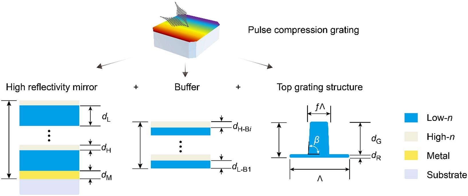
Figure 1.Schematic diagram of the all- and mixed-dielectric gratings in the traditional ‘reflectivity bottom + buffer + diffraction top’ combination design strategy.
In addition, a buffer is stacked with high-n and low-n films in a structure similar to an HR mirror. However, there are no specific restrictions on the number of films, structures and materials in a buffer as long as it moderately compensates for the high-efficiency in-phase condition[33]. The correct accumulation of the relative phase upon diffraction, propagation and reflection is required to achieve all light in the -1st order of reflection. Here, dH-Bi and dL-Bi indicate the physical thickness of the high-n and low-n films in the buffer, where the number of films is labeled with i.
Meanwhile, a top fine-tuned grating structure enables the redistribution of energy flow among the diffraction orders. The grating structure consists of partially etched or etch-through periodic pillars, where dG denotes the pillar depth, dR is the residual thickness of the etched films, f symbolizes the duty cycle in the base (the base width is the product of the grating period Λ and f) and β is the base angle of the pillar. Note that the All-L type is considered in the following design owing to the higher LIDT performance of SiO2.
All grating parameters were optimized by rigorous coupled-wave analysis (RCWA), which generates reliable calculation results of EFI distribution and DE (see more details in Refs. [28,29,34,35]). Here, the n values of HfO2 and SiO2 as high-n and low-n materials are 1.9 and 1.45 at 1053 nm, respectively. In order to obtain a constant complex refractive index
In this paper, a high-DE solution with a moderate line density was chosen to introduce the design paradigm. The 1300 l/mm MMDG was designed at a central wavelength of 1053 nm in transverse electric (TE) polarization with a 67.5° AOI. The design consisted of substrate/Au/(LH)5/LB1HB2/T/air. The regular film subsystem (LH)5 is a traditional HR structure, where H and L represent the HfO2 and SiO2 quarter-wavelength optical thickness layers, respectively. The SiO2 (LB1) and HfO2 (HB2) buffer combines the SiO2 top layer (T) to achieve a high DE and lay the foundation for a high LIDT. The physical parameters are dH = 152 nm, dL = 198 nm, dL-B1 = 466 nm, dH-B2 = 349 nm, dR = 308 nm, dG = 573 nm, f = 0.4 and
Figure 2 shows the DE map for the above design. Four regions are defined based on the line density. Incompatible Region I is above 1900 l/mm; accordingly, the grating period is less than 526 nm. As expected, the grating law is not satisfied for the 1053 nm laser. The stable Region II is between 1600 and 1900 l/mm, where the grating exhibits high dispersion and a large AOI. The effective solutions are concentrated and regularly extended with the increased line density. Anomalous Region III occupies a large range from 1000 to 1600 l/mm. In this region, the high-efficiency solutions deviate from the Littrow configuration. Obviously, small-deviation-angle solutions are connected into a narrow strip, illustrating the narrow AOI spectrum and high requirements for engineering layouts[37]. Conversely, large-deviation-angle solutions aggregate relatively large areas, implicating greater engineering feasibility. Turbulent Region IV is in the range of 600–1000 l/mm, containing a number of sharp dips generated by the guided-mode resonances (GMRs)[38,39]. These dips not only move relative to the line density but also have transverse pulsations along the AOI. Accordingly, the high-efficiency solutions generally appear at the Littrow angle, and numerous singular dissolutions appear chaotically.
![]()
Figure 2.The –1st order diffraction efficiency versus the incident angle and line density. The dashed line represents the Littrow angle at 1053 nm with the line density.
Figure 3 depicts the spectral bandwidth characteristics of these four regions. The spectrum in the 1000–1100 nm range was considered in this study; however, this could be broader. Notably, Region II had highly efficient solutions over a wide range. In comparison, the spectral bandwidth of Region III was narrower. However, the spectral performance significantly exceeded the bandwidth requirement of the Nd:glass-based laser system. Region IV is a split band in which effective solutions densely scratch the efficiency map.
![]()
Figure 3.The –1st order diffraction efficiency versus wavelength and line density.
3 High-dispersion large-incident-angle dielectric grating
In stable Region II, the effective grating structure is straightforward to construct and quickly converges to a solution with high dispersion and a large AOI. In this configuration, realizing a smaller EFI is the ultimate goal of design campaigns.
From a forward-looking perspective, two MMDG designs for the TE and TM polarizations are presented in Figure 4. One design is a 1740 l/mm MMDG, designed at 1053 nm for TE polarization with a 70° AOI. The design is as follows: substrate/Au/(LH)3/T/air. The physical parameters are dH = 167.2 nm, dL = 203.7 nm, dR = 28 nm, dG = 670 nm, f = 0.26 and
![]()
Figure 4.High-dispersion large-incident-angle dielectric grating with (a)–(d) 1740 l/mm in TE polarization and (e), (f) 1810 l/mm in TM polarization. The fabrication tolerance and EFI tolerance of the (a) duty cycle
The other is the 1810 l/mm MMDG, designed at 1053 nm in TM polarization with an AOI of 82.4°. The design is as follows: substrate/Au/HB1/T/air. The physical parameters are dH-B1 = 286 nm, dR = 286 nm, dG = 688 nm, f = 0.2 and
4 Moderate-dispersion large-deviation-angle dielectric grating
Anomalous Region III is a boon for an ultrabroad angular-deviation compressor. Considering a one-for-one replacement for the original compressor configuration of SG-II, a 1250 l/mm MMDG was designed for TE polarization in the Littrow configuration with a 29° deviation angle. The design consists of substrate/Au/(HL)15/HB1LB2HB3/T/air. The physical thicknesses are dH = 193 nm, dL = 171 nm, dH-B1 = 114 nm, dL-B2 = 453 nm, dH-B3 = 183 nm, dR = 200 nm, dG = 644 nm, f = 0.3 and
![]()
Figure 5.Low-dispersion large-deviation-angle dielectric grating. (a) Diffraction efficiency versus incident angle and wavelength in TE polarization. (b) Grating compressor architecture at an incident angle lower than (I), equal to (II) and higher than (III) the Littrow angle. (c) Normalized EFI distribution.
Figure 5(b) illustrates the multi-layout compatibility of this grating. The low-AOI design (I) exhibits higher dispersion for a given separation between the gratings and can have compressor geometry advantages for some systems. The Littrow angle design (II) requires out-of-plane operation for a total angular deviation greater than a few degrees. The high AOI design (III) exhibits a lower overall temporal dispersion for a given line density and separation and has the advantage that the intensity of the final grating is lower because of the larger projected angle of the beam on the grating, resulting in potentially higher pulse energy before laser damage occurs. As shown in Figure 5(c), the EFI values in the three cases spanned over a wide range from 2.2 to 6.56.
5 Low-dispersion dielectric grating at the Littrow angle
Turbulent Region IV presents problematic spectral features caused by GMRs. The careful design of the MDG can mitigate GMR dips to avoid substantial EFI and appreciable degradation of the LIDT. However, in some cases, GMRs cannot be eliminated completely. Although it is possible to eliminate the GMRs in the demand wavelength band, this leads to extremely poor preparation tolerances. Fortunately, the MDG tends to provide a high DE very close to the Littrow angle for most cases at TE and TM polarizations.
An ideal solution requires compromises in the DE and maximal EFI. As shown in Figure 6, each dot represents a 1150 l/mm MDG design at a 37° Littrow angle[40]. A sub/(2LH)15L/air design is used as the input structure, as shown in Figure 6(a). It can be observed that with such a design, the low EFI limits of the TM-polarized and TE-polarized MDGs are approximately 2.92 and 4.66, respectively. The EFI gain factor, defined as
![]()
Figure 6.Trade-off between maximal EFI in the grating pillar and average diffraction efficiency in the working wavelength band for a 1150 l/mm MDG. MDG selection for (a) single TE or TM polarization, and (b) polarization independence.
This section highlights a polarization-independent MMDG design that achieves high DE at both TE and TM polarizations. We select a non-regular structure: sub/Au/(LH)5/L/air. Figure 6(b) shows the dataset of the EFI and average DE from a large number of polarization-independent designs. From the above dataset, a design is picked to obtain a high DE and a high LIDT, in which the physical thicknesses are dL = 200 nm, dH = 150 nm, dR = 66 nm, dG = 1283 nm, f = 0.633 and
6 Discussion
The energy-loading capacity is determined by the grating aperture and LIDT on the grating surface. Therefore, it can be expressed using the following simple formula:
where
Figure 7 depicts the
![]()
Figure 7.Energy scaling factor distribution. The circle represents the design in this paper. The purple circle represents the 1810 l/mm ultra-low EFI design in Section 3. The blue circles denote the 1250 l/mm ultra-broad deviation-angle design in Section
7 Conclusion
In conclusion, a design paradigm was proposed for all- and mixed-dielectric pulse compression gratings. The grating solution was classified into four regions according to the line density: incompatible Region I, stable Region II, anomalous Region III and turbulent Region IV. At 1600–1900 l/mm, Region II concentrated solutions with a high dispersion and large AOI, generating an ultra-low EFI and large projection ratios. The solution in Region III, from 1200 to 1600 l/mm, had an ultra-broad deviation angle and was compatible with a wide range of compressor architectures. In Region IV, perturbed by GMRs, effective solutions with a low dispersion below 1200 l/mm appeared at the Littrow mounting. Although the partition of the line density in Regions I–IV varied for a given design, the properties of each region were unique. In addition, the potential of the angle and TM polarization to maximize the grating energy-loading capacity was elucidated by analyzing the energy scaling factor. Our research paves the way for designing and matching the best high-energy gratings for Nd:glass PW laser compressors.
References
[1] D. Strickland, G. Mourou. Opt. Commun., 55, 447(1985).
[2] A. Dubietis, G. Jonušauskas, A. Piskarskas. Opt. Commun., 88, 437(1992).
[3] W. Wang, K. Feng, L. Ke, C. Yu, Y. Xu, R. Qi, Y. Chen, Z. Qin, Z. Zhang, M. Fang, J. Liu, K. Jiang, H. Wang, C. Wang, X. Yang, F. Wu, Y. Leng, J. Liu, R. Li, Z. Xu. Nature, 595, 516(2021).
[4] P. W. Hatfield, J. A. Gaffney, G. J. Anderson, S. Ali, L. Antonelli, S. B. Du Pree, J. Citrin, M. Fajardo, P. Knapp, B. Kettle, B. Kustowski, M. J. MacDonald, D. Mariscal, M. E. Martin, T. Nagayama, C. A. J. Palmer, J. L. Peterson, S. Rose, J. J. Ruby, C. Shneider, M. J. V. Streeter, W. Trickey, B. Williams. Nature, 593, 351(2021).
[5] H. Takabe, Y. Kuramitsu. High Power Laser Sci. Eng., 9, e49(2021).
[6] R. Betti, O. A. Hurricane. Nat. Phys., 12, 435(2016).
[7] C. N. Danson, C. Haefner, J. Bromage, T. Butcher, J. F. Chanteloup, E. A. Chowdhury, A. Galvanauskas, L. A. Gizzi, J. Hein, D. I. Hillier, N. W. Hopps, Y. Kato, E. A. Khazanov, R. Kodama, G. Korn, R. Li, Y. Li, J. Limpert, J. Ma, C. H. Nam, D. Neely, D. Papadopoulos, R. R. Penman, L. Qian, J. J. Rocca, A. A. Shaykin, C. W. Siders, C. Spindloe, S. Szatmári, R. M. G. M. Trines, J. Zhu, P. Zhu, J. D. Zuegel. High Power Laser Sci. Eng., 7, e54(2019).
[8] C. N. Danson, M. White, J. R. M. Barr, T. Bett, P. Blyth, D. Bowley, C. Brenner, R. J. Collins, N. Croxford, A. E. B. Dangor, L. Devereux, P. E. Dyer, A. Dymoke-Bradshaw, C. B. Edwards, P. Ewart, A. I. Ferguson, J. M. Girkin, D. R. Hall, D. C. Hanna, W. Harris, D. I. Hillier, C. J. Hooker, S. M. Hooker, N. Hopps, J. Hull, D. Hunt, D. A. Jaroszynski, M. Kempenaars, H. Kessler, S. P. L. Knight, S. Knight, A. Knowles, C. L. S. Lewis, K. S. Lipton, A. Littlechild, J. Littlechild, P. Maggs, G. P. A. Malcolm, S. P. D. Mangles, W. Martin, P. McKenna, R. O. Moore, C. Morrison, Z. Najmudin, D. Neely, G. H. C. New, M. J. Norman, T. Paine, A. W. Parker, R. R. Penman, G. J. Pert, C. Pietraszewski, A. Randewich, N. H. Rizvi, N. Seddon, Z. Sheng, D. Slater, R. A. Smith, C. Spindloe, R. Taylor, G. Thomas, J. W. G. Tisch, J. S. Wark, C. Webb, S. M. Wiggins, D. Willford, T. Winstone. High Power Laser Sci. Eng., 9, e18(2021).
[9] Z. Li, Y. Leng, R. Li. Laser Photonics Rev., 17, 2100705(2022).
[11] B. Rus, P. Bakule, D. Kramer, J. Naylon, J. Thoma, M. Fibrich, J. T. Green, J. C. Lagron, R. Antipenkov, J. Bartoníček, F. Batysta, R. Baše, R. Boge, S. Buck, J. Cupal, M. A. Drouin, M. Ďurák, B. Himmel, T. Havlíček, P. Homer, A. Honsa, M. Horáček, P. Hríbek, J. Hubáček, Z. Hubka, G. Kalinchenko, K. Kasl, L. Indra, P. Korous, M. Košelja, L. Koubíková, M. Laub, T. Mazanec, A. Meadows, J. Novák, D. Peceli, J. Polan, D. Snopek, V. Šobr, P. Trojek, B. Tykalewicz, P. Velpula, E. Verhagen, Š. Vyhlídka, J. Weiss, C. Haefner, A. Bayramian, S. Betts, A. Erlandson, J. Jarboe, G. Johnson, J. Horner, D. Kim, E. Koh, C. Marshall, D. Mason, E. Sistrunk, D. Smith, T. Spinka, J. Stanley, C. Stolz, T. Suratwala, S. Telford, T. Ditmire, E. Gaul, M. Donovan, C. Frederickson, G. Friedman, D. Hammond, D. Hidinger, G. Chériaux, A. Jochmann, M. Kepler, C. Malato, M. Martinez, T. Metzger, M. Schultze, P. Mason, K. Ertel, A. Lintern, C. Edwards, C. Hernandez-Gomez, J. Collier, G. Korn, L. O. Silva, 10241(2017).
[12] C. P. J. Barty, M. Key, J. Britten, R. Beach, G. Beer, C. Brown, S. Bryan, J. Caird, T. Carlson, J. Crane, J. Dawson, A. C. Erlandson, D. Fittinghoff, M. Hermann, C. Hoaglan, A. Iyer, L. Jones, I. Jovanovic, A. Komashko, O. Landen, Z. Liao, W. Molander, S. Mitchell, E. Moses, N. Nielsen, H. Nguyen, J. Nissen, S. Payne, D. Pennington, L. Risinger, M. Rushford, K. Skulina, M. Spaeth, B. Stuart, G. Tietbohl, B. Wattellier. Nucl. Fusion, 44, S266(2004).
[13] J. H. Kelly, L. J. Waxer, V. Bagnoud, I. A. Begishev, J. Bromage, B. E. Kruschwitz, T. J. Kessler, S. J. Loucks, D. N. Maywar, R. L. McCrory, D. D. Meyerhofer, S. F. B. Morse, J. B. Oliver, A. L. Rigatti, A. W. Schmid, C. Stoeckl, S. Dalton, L. Folnsbee, M. J. Guardalben, R. Jungquist, J. Puth, M. J. Shoup, D. Weiner, J. D. Zuegel. J. Phys. IV, 133, 75(2006).
[14] N. Miyanaga, H. Azechi, K. A. Tanaka, T. Kanabe, T. Jitsuno, J. Kawanaka, Y. Fujimoto, R. Kodama, H. Shiraga, K. Knodo, K. Tsubakimoto, H. Habara, J. Lu, G. Xu, N. Morio, S. Matsuo, E. Miyaji, Y. Kawakami, Y. Izawa, K. Mima. J. Phys. IV, 133, 81(2006).
[15] J. Zhu, X. Xie, M. Sun, J. Kang, Q. Yang, A. Guo, H. Zhu, P. Zhu, Q. Gao, X. Liang, Z. Cui, S. Yang, C. Zhang, Z. Lin. High Power Laser Sci. Eng., 6, e29(2018).
[16] Y. Hou, H. Li, L. Zhang. J. Non-Cryst. Solids, 600, 121988(2023).
[17] https://www.icuil.org/. https://www.icuil.org/
[18] B. C. Stuart, M. D. Feit, A. M. Rubenchik, B. W. Shore, M. D. Perry. Phys. Rev. Lett., 74, 2248(1995).
[19] N. Bonod, J. Neauport. Adv. Opt. Photonics, 8, 156(2016).
[20] M. D. Perry, R. D. Boyd, J. A. Britten, D. Decker, B. W. Shore, C. Shannon, E. Shults. Opt. Lett., 20, 940(1995).
[21] F. Kong, Y. Jin, D. Li, W. Chen, M. Zhu, T. Wang, C. Li, H. He, G. Xu, J. Shao, G. J. Exarhos, V. E. Gruzdev, J. A. Menapace, D. Ristau, M. J. Soileau, 8530(2012).
[22] I. Jovanovic, C. G. Brown, B. C. Stuart, W. A. Molander, N. D. Nielsen, B. F. Wattellier, J. A. Britten, D. M. Pennington, C. P. J. Barty, 5647(2005).
[23] A. A. Kozlov, S. G. Demos, D. Canning, B. N. Hoffman, B. E. Kruschwitz, A. L. Rigatti, N. Savidis, L. J. Waxer. Opt. Eng., 60, 031008(2021).
[24] B. W. Shore, M. D. Perry, J. A. Britten, R. D. Boyd, M. D. Feit, H. T. Nguyen, R. Chow, G. E. Loomis, L. Li. J. Opt. Soc. Am. A, 14, 1124(1997).
[25] J. Wang, Y. Jin, J. Ma, T. Sun, X. Jing. Appl. Opt., 49, 2969(2010).
[26] J. Neauport, N. Bonod, S. Hocquet, S. Palmier, G. Dupuy. Opt. Express, 18, 23776(2010).
[27] A. B. Jerald, A. M. William, M. K. Aleksey, P. J. B. Christopher, 5273(2004).
[28] Y. Han, Y. Jin, F. Kong, Y. Wang, Y. Zhang, H. Cao, Y. Cui, J. Shao. Appl. Phys. Lett., 120, 113502(2022).
[29] S. Liu, Z. Shen, W. Kong, J. Shen, Z. Deng, Y. Zhao, J. Shao, Z. Fan. Opt. Commun., 267, 50(2006).
[30] N. Bonod, J. Néauport. Opt. Commun., 260, 649(2006).
[31] https://www.plymouthgrating.com/. https://www.plymouthgrating.com/
[33] H. Wei, L. Li. Appl. Opt., 42, 6255(2003).
[34] H. Guan, H. Chen, J. Wu, Y. Jin, F. Kong, S. Liu, K. Yi, J. Shao. Opt. Lett., 39, 170(2014).
[35] J. Chen, Y. Zhang, Y. L. Wang, F. Kong, H. Huang, Y. Wang, Y. Z. Jin, P. Chen, J. Xu, J. Shao. Opt. Lett., 42, 4016(2017).
[36] W. Werner, K. Glantschnig, C. Ambrosch-Draxl. J. Phys. Chem. Ref. Data, 38, 1013(2009).
[37] B. Webb, M. J. Guardalben, C. Dorrer, S. Bucht, J. Bromage. Appl. Opt., 58, 234(2019).
[38] J. Wang, Y. Jin, J. Ma, J. Shao, Z. Fan. Chin. Phys. B, 19, 276(2010).
[39] D. A. Alessi, H. T. Nguyen, J. A. Britten, P. A. Rosso, C. Haefner. Opt. Laser Technol., 117, 239(2019).
[40] Š. Vyhlídka, P. Trojek, D. Kramer, D. Peceli, F. Batysta, J. Bartoníček, J. Hubáček, T. Borger, R. Antipenkov, E. Gaul, T. Ditmire, B. Rus, P. Bakule, C. L. Haefner, 11034(2019).
[41] L. Lamaignère, A. Ollé, M. Chorel, N. Roquin, A. A. Kozlov, B. N. Hoffman, J. B. Oliver, S. G. Demos, L. Gallais, R. A. Negres, A. Melninkaitis. Opt. Eng., 60, 031005(2021).
[42] J. Néauport, N. Bonod, 7132(2008).


Set citation alerts for the article
Please enter your email address

© Copyright 2018-2021 | Chinese Laser Press. All Rights Reserved 沪ICP备15018463号-20