1Department of Computer Science and Electronics, Kyushu Institute of Technology, Fukuoka 820-8502, Japan
2Department of Electrical Energy and Computer Engineering, Gyeongju University, 188 Taejongro, Gyeongju City, KyeongsangBukdo, 38065, Republic of South Korea
3Department of Electrical, Electronic, and Control Engineering, IITC, Hankyong National University, 327 Chungang-ro, Anseong-si, Gyonggi-do 456-749, Republic of South Korea
Min-Chul Lee, Kotaro Inoue, Cheol-Su Kim, Myungjin Cho. Regeneration of elemental images in integral imaging for occluded objects using a plenoptic camera[J]. Chinese Optics Letters, 2016, 14(12): 121101
Copy Citation Text
In this Letter, we propose an elemental image regeneration method of three-dimensional (3D) integral imaging for occluded objects using a plenoptic camera. In conventional occlusion removal techniques, the information of the occlusion layers may be lost. Thus, elemental images have cracked parts, so the visual quality of the reconstructed 3D image is degraded. However, these cracked parts can be interpolated from adjacent elemental images. Therefore, in this Letter, we try to improve the visual quality of reconstructed 3D images by interpolating and regenerating virtual elemental images with adjacent elemental images after removing the occlusion layers. To prove our proposed method, we carry out optical experiments and calculate performance metrics such as the mean square error (MSE) and the peak signal-to-noise ratio (PSNR).
Integral imaging, which was first proposed by Lippmann in 1908[1], has been used to develop next-generation three-dimensional (3D) imaging and display techniques. To obtain and visualize 3D images, two main steps are required: pickup and reconstruction. In pickup, rays from 3D objects can be captured through lenslet array on an image sensor such as charge-coupled device (CCD). These captured rays are multiple two-dimensional (2D) images with different perspectives for 3D objects, which are referred to as elemental images. In the reconstruction or display stage, these elemental images are printed or displayed on a display device, such as a liquid crystal display (LCD), through the homogeneous lenslet array used in pickup so 3D images can be observed without special viewing glasses. Integral imaging does not require the coherent light source that is used in holography. In addition, it provides full color, full parallax, and continuous viewing points of 3D objects. Especially, it provides depth information of 3D objects using a passive imaging system. Therefore, it can be applied to occlusion removal techniques for 3D objects[2–11].
Since integral imaging can obtain multi-view information of 3D objects, a depth map may be generated by varying the ratios of the viewing point and elemental images. Thus, the occlusion may be removed by classifying between objects and occlusion layers using the depth map and elemental images. However, this method has two main problems. The first problem is the resolutions of the elemental images and depth map are very low due to the lenslet array based integral imaging. Another problem is the information of elemental images may be lost for the occlusion removal.
In this Letter, to solve these problems, we propose an elemental image regeneration method of 3D integral imaging for occluded objects using a plenoptic camera. A plenoptic camera, which is a modified version of an integral imaging system, can record a light field (location and direction of rays) by placing the main imaging lens in front of the lenslet array. It can capture a depth map with high resolution and an all-in-focus image in a single shot, and it can simplify the process for the conventional occlusion removal technique. To record elemental images with high resolutions, in this Letter, we used synthetic aperture integral imaging (SAII)[12] by Jang et al.
Sign up for Chinese Optics Letters TOC. Get the latest issue of Chinese Optics Letters delivered right to you!Sign up now
SAII can capture an elemental image with the same resolution as the one of the image sensor by replacing the lenslet array with a camera array for to improve the resolution of elemental images. Finally, the cracked parts of the elemental images may be interpolated from adjacent elemental images to enhance them. Since elemental images have multi-view information, it is possible to interpolate the cracked parts from adjacent elemental images, which can be carried out by inverse computational integral imaging reconstruction (CIIR)[2,13–16].
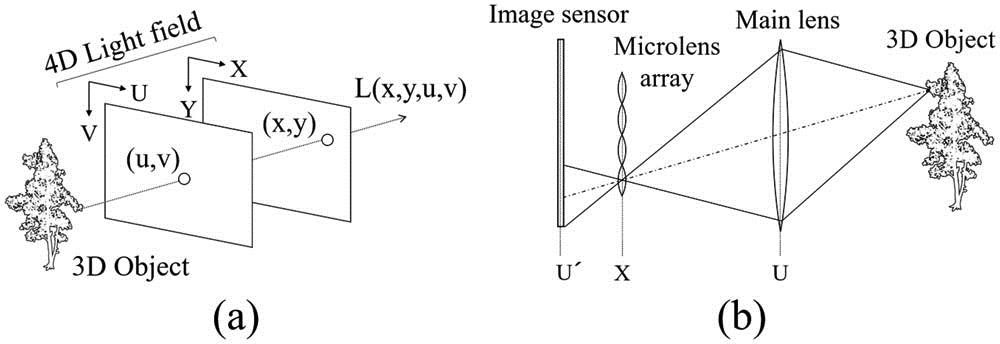
First, we present our proposed method. A light field is a vector function presented for the position and angle of rays. In general, a light field can be defined as 5 dimensions that consist of 3D space coordinates and 2D angles. This is referred to as 5D light field. However, light intensity is invariant in an optical system, according to the brightness invariant principle. Therefore, a 5D light field can be redefined as a 4D light field. A plenoptic camera records this 4D light field so it can adjust the position of the focal plane for the image or estimate the depth map.
A 4D light field function is shown in Fig. 1(a). It is rays from the objects, which can be recorded as the intersection points of two 2D planes. That is, are coordinates and on the XY and UV planes, respectively. They are the same as the intersection coordinates on one of the 2D planes and the angles of two axes. The concept of a 4D light field for a plenoptic camera is illustrated in Fig. 1(b). The difference between a plenoptic camera and a conventional camera is the lenslet array placed in front of the main imaging lens. In a conventional camera, rays can be recorded on the coordinates of the image sensor (i.e., 2D information). However, in a plenoptic camera, the intersection coordinates of rays on two planes can be found by imaging object rays through both the main lens and the lenslet array.
Figure 1.4D light field function. (a) Overview and (b) plenoptic camera.
Plenoptic cameras can reconstruct the image focused at a certain position by recording the 4D light field. This technique is called refocusing, which can be implemented by shifting the virtual image sensor plane. It is very simple and is carried out by shifting and averaging sub-aperture images, as shown in Fig. 2[17]. It is similar to CIIR, but its equations are different because it uses the light field function.
For simplicity, let us consider the movement of 2D virtual image sensor plane X, as shown in Fig. 3. The X plane is placed a distance from the U plane, and light field is rays passing through the coordinate of the U plane and the coordinate of the X plane. For refocusing, when the X plane is moved to the plane, where it is a distance from the U plane, the recorded light field on the plane can be described as the movement of the coordinate on . When the expanding coefficient is , can be written as follows[18]: This equation can be extended as a 4D light field: Moving the virtual image sensor plane is the same as moving the position of the XY plane in the recording coordinates of the light field. It is well known that a 2D image can be transformed from a 4D light field by integrating the light field. Therefore, the image at distance , can be described as follows: By substituting Eq. (2) into Eq. (3), we can obtain the following equation: From Eq. (4), it can be seen that the image can be reconstructed by shifting and averaging the , coordinates of light field and expanding the image with expanding coefficient . That is, when the th column and th row sub-aperture image is , the 2D image can be transformed by shifting and averaging sub-aperture images instead of elemental images in integral imaging. Therefore, Eq. (4) can be rewritten[18]
The depth map can be estimated using the light field. This function is included in Lytro software, but the algorithm has not been opened to the public. Thus, in this Letter, we present our own depth map estimation. The depth map has a 16-bit grayscale and its brightness is determined by the Lambda used for refocusing. LambdaMin is brightness 0, and LambdaMax is brightness . To estimate the physical distance from these Lambdas, the calibration process is required because the brightness of the depth map is different from the physical distance.
Regeneration of elemental images has two main stages: occlusion removal, and interpolation of cracked parts caused by occlusion removal. Table 1 describes the system parameters and their definition, and the regenerated images are shown in Fig. 4.
Figure 4.Image of equation (, ): (a) EI, (b) , (c) OL, (d) OREI, (e) VEI, and (f) REI.
Occlusion removal can be implemented by using a certain threshold of the depth map. Let the depth map be and the occlusion layer be OL. Then, OL can be written as where is the th column and the th row occlusion layer, , give the pixel position, and Th is the threshold value for occlusion removal. Then, occlusions can be removed from the elemental images. Let the elemental image be EI and elemental image with occlusions removed be OREI. OREI is written as Since the elemental image has a lot of zero brightness after occlusion removal, the visual quality of the elemental image may be degraded. Thus, in this Letter, the elemental image is interpolated and regenerated by using adjacent elemental images. Regeneration can be carried out by shifting adjacent elemental images and generating the virtual elemental image.
OREI can be split by intensities of the depth map, as follows: where is the intensity of the depth map, and is the maximum intensity of the depth map. Then, the movement of elemental images is calculated as depicted in Fig. 5(a). Let be the coordinates of the current regenerated image and be the coordinates of the image for interpolation. The movements of the elemental image in the and directions, and , are written by where is the distance between cameras for SAII. Using these movements, shifting pixels for each elemental image as shown in Fig. 5(b) can be written as follows: where and are the number of pixels for the image sensor in the and directions, and is the function transformed by the intensity of the depth map in relation to the physical distance. This function depends on the specifications of the plenoptic camera and the calibration methods. Thus, the virtual elemental image VEI can be written as where is the superposition matrix for CIIR. Equation (11) is the inverse of CIIR. Finally, the regenerated elemental image can be obtained from OREI and VEI as follows: To prove our proposed method, we carried out computer simulations. The parameters are described in Table 1. In CIIR, the shifting pixels of each elemental image and are as follows: Finally, the reconstructed 3D image at distance can be obtained by the following equation: Next, we show the experimental results. The depth map from the Lytro software cannot present the physical depth. Thus, we need to place the reference object at a fixed distance and measure the distance by stereo matching. Therefore, we can estimate the relation between the intensity of the depth map and the physical depth. In the pickup stage, LYTRO ILLUM is used, where the resolution of the camera is , the focal length of camera lens , the refocus range is 400–750 mm, and the distance between cameras . When we know the shifting pixels () between the two elemental images, we can calculate the depth using the following equation:
Figure 5.Overview of the algorithm. (a) Movement of elemental images and (b) shifted pixels for regeneration.
Table 2 and Fig. 6 show the measurement results. These depths are converted to the intensity of the depth map . As shown in Fig. 6, the relation between the intensity of the depth map and the physical depth is linear. Thus, the linear approximation can be found by the least squares method. Therefore, the experimental equation for the transformation between the intensity of the depth map and the physical depth is This equation is used to calculate and in the regeneration of elemental images.
In our experiment, there are two pickup scenarios: with occlusion and without occlusion. 3D objects without occlusion are used to calculate the mean square error (MSE) and the peak signal-to-noise ratio (PSNR) as follows: where is the expectation operator, Ref is the reference image, is the reconstruction results, and is the maximum pixel intensity of the image. The occlusion is placed in front of the left shoulder of the object.
Figure 7 shows the reconstructed 3D images at the reconstruction distance for each method. The reconstructed 3D images using the elemental images without occlusion shown in Fig. 7(a) are the references for the MSE and PSNR. Figures 7(b) and 7(c) show the reconstructed 3D images using elemental images with the occlusion removed conventionally and the reconstructed 3D images by our proposed method, respectively. As shown in the enlarged figure, the characters “BF-37” on the shoulder of the object can be easily recognized in Fig. 7(f). To evaluate the visual quality of the reconstructed 3D images, we calculate the MSE and PSNR as shown in Fig. 8. Thus, we see our proposed method can obtain better results. (The MSE is improved by 60%, and the PSNR is improved by ).
Figure 7.Experimental results at : (a) original, (b) conventional occlusion removal, (c) proposed method, (d)–(f) enlarged views of (a)–(c), respectively.
In this Letter, we propose a regeneration technique for elemental images in integral imaging using a plenoptic camera after removing the occlusions. In conventional methods, the image information may be lost after occlusion removal. On the other hand, in our proposed method, the image information can be interpolated by adjacent elemental images after occlusion removal. However, our method has some problems. The visual quality of the regenerated elemental images depends on the accuracy of the depth map or calibration. In addition, our method uses an averaging process for the 3D reconstruction, so high spatial frequencies may be lost. We will look for a solution to these problems in the future.
References
[1] G. Lippmann. C. R. Acad. Sci., 146, 446(1908).
Min-Chul Lee, Kotaro Inoue, Cheol-Su Kim, Myungjin Cho. Regeneration of elemental images in integral imaging for occluded objects using a plenoptic camera[J]. Chinese Optics Letters, 2016, 14(12): 121101