Abstract
The dissipative sensing based on a self-interference microring resonator composed of a microring resonator and a U-shaped feedback waveguide is demonstrated experimentally. Instead of a frequency shift induced by the phase shift of the waveguide or the microcavity, the dissipative sensing converts the phase shift to the effective external coupling rate, which leads to the change of linewidth of the optical resonance and the extinction ratio in the transmission spectrum. In our experiment, the power dissipated from a microheater on the feedback waveguide is detected by the dissipative sensing mechanism, and the sensitivity of our device can achieve 0.22 dB/mW. This dissipative sensing mechanism provides another promising candidate for microcavity sensing applications.1. INTRODUCTION
Optical sensing is one of the most important pillars of modern information technology. Various platforms have been utilized to perform optical sensing, such as Fabry–Perot cavities [1], optical fibers/waveguides [2,3], surface plasmonic nano-structures [4,5], and whispering gallery mode (WGM) resonators [6–22]. Thanks to the high optical quality factor (-factor) and the small mode volume, WGM resonators show excellent sensing performance with high sensitivity and low limit of detection among these platforms. In recent years, the WGM resonators have been used for many types of sensing, such as temperature [6,7], force detection [15–18], magnetometry [19], chemical sensing [20–22], and biosensing [5,23–25].
The mechanism behind WGM sensors can be generally classified into two categories: dispersive sensing and dissipative sensing. The principle of dispersive sensing is to obtain the variation of target parameter by detecting the resonance wavelength shift [6], whose detection limitation is mainly attributed to the frequency instability of the laser. Alternatively, the modal splitting in the traveling wave WGM microresonator can be used for a specific sensing purpose [8,9], which can be free from the fluctuation of the laser frequency. The dissipative sensing can be realized by monitoring the change of the linewidth, where the existence of the lossy analyte can induce mode broadening [10]. In the past few years, a lot of efforts have been devoted to improve the sensitivity and reduce the limit of detection of microresonator sensors. However, to date, most WGM sensors based on dispersive sensing are limited by laser frequency noise, while the dissipative sensing works only for WGM sensors coupled with lossy analytes with near-field interaction [10], which can contaminate the resonators and limit the cycle times.
In this paper, we experimentally demonstrate a self-interference microring resonator (SIMRR) on a chip and verify the general approach for the dissipative sensing mechanism without the limitation of near-field interaction [26]. The SIMRR consists of a microring resonator and a U-shaped feedback waveguide, which is an interference arm coupling the microring resonator twice. Similar structures have been studied in sensing applications [27–29], where the role of the feedback waveguide is just to expand the quasi-free spectral range, but the underlying dissipative sensing mechanism has not been revealed yet. Here, the spectrum linewidth and the extinction ratio can be tuned by changing the phase of the feedback waveguide; hence, the dispersive interaction gives rise to the dissipative detection. Therefore, almost all types of sensing experiments based on the dispersive sensing mechanism can be transferred and performed on our dissipative sensing mechanism systems as well. In addition, this dissipative sensing holds the advantage of achieving better sensing performance than dispersive sensing, because of being immune to laser frequency noises [30]. And as a result of taking the feedback waveguide as the sensing part, the degeneration of the high- microresonator can be avoided during this dissipative detection, which is not affected by the contamination of the waveguide [26,30] and quite different from the dissipative sensing used in the previous sensors [5,8–11,20,21,31]. Therefore, our sensing device based on the dissipative sensing mechanism is robust and can be used many times.
Sign up for Photonics Research TOC. Get the latest issue of Photonics Research delivered right to you!Sign up now
2. THEORETICAL ANALYSIS
As shown in Fig. 1(a), the SIMRR consists of a microring resonator and an interference sensing arm. The coupling mechanism between the microring and the waveguide is modeled by means of a beam splitter (BS) matrix, in which and represent the amplitude reflectivity and transmittance of the directional coupler (). Compared to the traditional waveguide loaded microring resonator, the microring of SIMRR has coupled for twice with the waveguide, and thus the sensing arm induces a phase difference between the two coupling regions. As for single coupling, the external loss and are related as , where is the round-trip time, with being the group velocity and the radius of the microring. Due to the propagation loss in the waveguide/microring, the intrinsic loss of the microring is with propagation attenuation constant .
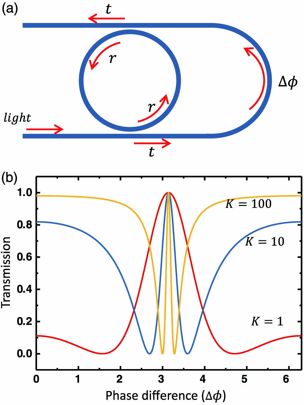
Figure 1.(a) Schematic of the self-interference microring resonator. (b) Simulated transmission at resonance frequency with different ratios varying with the phase difference, which is induced by the feedback waveguide.
For the waveguide to microring coupling with two coupling regions [Fig. 1(a)], we have the overall coupling matrix as Here, is the phase difference induced by the sensing arm. can be changed according to the optical path difference between the microring and the sensing arm, i.e. where and represent the refractive index of the microring and sensing arm, respectively. and are the lengths of the half microring and sensing arm, respectively. If is fixed, changes according to , then Therefore, the effective transmittance becomes and The transmission of the SIMRR can be derived as [32] where is the coupling parameter.
As shown in Eq. (7), the change of mainly depends on and ; in order to get better performance of sensing sensitivity, we discuss these two parameters systematically. As proposed in Ref. [26], the sensitivity of SIMRR reaches its maximum value at , and the sensitivity increases gradually with the increase of in the weak coupling region. In our experiment, because the gap between the high-quality microring and the waveguide is limited by the semiconductor process, and the coupling strength of this kind of single point coupling is relatively weak, the SIMRR will predictably work in the weak coupling region, and thus the transmission coefficient is far less than reflection coefficient . Here, we supposed is close to 1.
To get the straightforward insight of the regular of changes according to , we numerically calculate Eq. (7). Figure 1(b) shows the calculated extinction ratio versus for different values of . The transmittance changes rapidly when is near , and with the increase of , the slope of the spectra increases significantly.
3. DEVICE FABRICATION AND EXPERIMENTAL SETUP
In our experiments, the SIMRR was fabricated with low-pressure chemical vapor deposition (LPCVD) silicon nitride () waveguides embedded in silicon dioxide (). The wafer was made up of 500 μm silicon, 3 μm wet oxidation , and 350 nm . The waveguides and microring resonators were patterned using e-beam lithography with hydrogen-silsesquioxane (HSQ) resist (FOx-16). Then, the film was etched with a -based gas in an inductively coupled plasma (ICP) etcher. After removing the resist with buffered oxide etch (BOE), an upper cladding of 3 μm silicon dioxide was then deposited to protect the sample. Finally, a microheater was formed by depositing a layer of 300 nm Au and 10 nm Ti using e-beam evaporation on the upper cladding right above the U-shaped feedback waveguide, as shown in Fig. 2. The radius of the microring was 100 μm, and the length of the feedback waveguide was 250 μm. The cross section of the microring and waveguide was . The gap between the microring and the waveguide was designed for several sizes to vary the coupling strength of microring resonators. The waveguide loss coefficient was .

Figure 2.Schematic of the experiment setup of the self-interference microring sensor. The laser is coupled into and out of the microring using fiber lens. FPC, fiber polarization controller; DSO, digital oscilloscope. Inset shows an optical microscopy picture of the device.
The experimental setup for SIMRR-based dissipative sensing is illustrated in Fig. 2. A tunable continuous-wave (CW) laser with a typical linewidth of and a wavelength tuning range from 1550 to 1630 nm was used to couple the light in and out of the SIMRR through tapered lens fibers. A polarization controller was used to control the polarization in the waveguide to excite relevant WGMs. The coupling loss of lens fibers is measured to be at each facet. To demonstrate the dissipative sensing mechanism, the microheater above the feedback waveguide connected to a current source was used to change the temperature of the waveguide, which induced the phase shift in the waveguide due to the thermo-optics effect. Because the temperature of the buried waveguide is hard to measure and the resistance of the microheater changes with the variation of the temperature, we take the applied electrical power as the target parameter. When the change in the microheater resistance is negligible, current or voltage applied on the microheater might be regarded as the target parameter.
4. EXPERIMENTAL RESULTS
As analyzed above, the , i.e., , is critical for the dissipative sensing, so we made devices with directional couplers of different geometry parameters, i.e., the gap or 200 nm between the microring and bus waveguide. Figure 3(a) shows the experimentally measured transmission spectra of the fundamental transverse electric (TE) modes family in the SIMRR with . The oscillating background in the spectrum is derived from the Fabry–Perot interference of the light in the bus waveguide, due to the two smooth coupling facets of the waveguide. The extinction ratio and the linewidth of different optical modes show significant differences, which are caused by different for optical modes at different wavelengths. When applying an electrical power , the resonance wavelength slightly shifts towards longer wavelength; however, the extinction ratio changes evidently, as shown in Fig. 3(b). Our focus is mainly on the variation of the extinction ratio in the transmission spectrum, especially in the green region. Of course, the resonance wavelength shift can also be observed with expanded transmission area.
Figure 3.(a), (b) Transmission spectra of the SIMRR system at two different applied electrical powers of the microheater: (black lines), (red lines). The green area highlights the change of transmission spectrum analyzed below. The insets show the expanded transmission spectra of the green area.
Increasing the applied electrical power slowly, the transmission of one resonance in the green region was recorded and is shown in Fig. 4(a), which indicates the resonance wavelength has a red shift, and the extinction ratio and the linewidth vary periodically. It is observed that the extinction ratio is small and the linewidth is relatively large without heating (), which corresponds to the over-coupling condition. When the electrical power is increased, the extinction ratio increases and the linewidth decreases at the same time. Critical coupling is achieved at electrical power around 0.106 W. The extinction ratio is about 15 dB and the loaded -factor is about at this time. Then the extinction ratio sharply reduces to zero as the electrical power is continuously increased. Meanwhile, the linewidth still decreases at this step, achieving the under-coupling regime. Eventually, as the resonance mode disappears, the linewidth decreases to a minimum value, corresponding to the highest -factor. As the electrical power is increased continuously, the variation of the extinction ratio exhibits a mirror symmetry with the previous change, which is in great agreement with our theoretical prediction. For other optical modes, similar behavior has also been observed. The transmission spectra and the relationship between the extinction ratio and the effective refractive index of SIMRR with are presented in Fig. 4(b). Because of the stronger interaction between the microring and the feedback waveguide, the extinction ratio and the linewidth of an SIMRR with 100 nm gap vary more obviously than that of a 200 nm gap SIMRR. An extinction ratio of about 18 dB and an intrinsic -factor of can be achieved in this device.
Figure 4.(a), (b) Measured transmission spectra of different gaps with varying voltages applied to the microheater above the feedback waveguide: (a) gap , (b) gap . (c), (d) Effective external coupling rate and extinction ratio varying with applied power.
To investigate the respective relationship between the phase shift and the extinction ratio as well as the linewidth more clearly, scatter plots can be seen in Figs. 4(c) and 4(d), where the axis is the applied electrical power, and the axis is the effective external loss rate for Fig. 4(c) and the normalized transmission for Fig. 4(d), respectively. Since the phase difference is induced by the feedback waveguide, which changes almost linearly with the applied power, the axis can be equivalent to the phase difference . As shown in Fig. 4(c), with the increase of applied power, three coupling cases—over-coupling, critical coupling, and under-coupling regimes—are experienced successively. The experimental points are fitted well with Eq. (5), showing a cosine envelope. For the extinction ratio shown in Fig. 4(d), the result is fitted by Eq. (7), and the theoretical curve fits well, especially in the large slope region, as we will discuss below.
Since the extinction ratio variation is not linearly proportional to the change of phase difference within the entire period, the section with a good linear response and a large slope is usually chosen as the dissipative sensing operation range for high sensing sensitivity. As indicated in Fig. 4(d), two sections meet the requirement in the whole period. One is from the left critical coupling position to the zero extinction position, and the other is from the zero extinction position to the right coupling position. Hence, we select the part of the curve between the zero extinction position and critical coupling position as the sensing operation range.
According to Fig. 4(d), we can estimate that the sensitivity of our device is approximately 0.22 dB/mW () and 0.16 dB/mW (), respectively. For our devices, is about 0.5 GHz, corresponding to an intrinsic -factor of about . The optimal sensitivity is estimated to be 0.38 dB/mW with , and the corresponding limit of detection (LOD) is estimated as . Therefore, the gap smaller than 100 nm is critical to reach this optimal sensitivity. If the intrinsic -factor of our device can reach as high as [33], the optimal sensitivity of 3.7 dB/mW and LOD of can be achieved.
Generally, the SIMRR based on a dissipative sensing mechanism can be used as detectors in a variety of sensing fields. First of all, considering the phase shift caused by the change of the effective refractive index of the feedback waveguide via the thermo-optic effect, temperature sensing is well suited to our dissipative sensing device. Second, since the planar waveguides have evanescent waves extending into the ambient environments, by bonding a microfluid channel on top of the feedback waveguide, analytes can interact with the waveguide evanescent field. Chemical sensing as in distinguishing the concentration or the composition of the solution can be performed on our device. In addition, nanoparticles, molecules, and viruses can be attached on the surface of the feedback waveguide, which also can change phase shift of the waveguide, and eventually induce the variation of the linewidth and the extinction ratio.
5. CONCLUSIONS
In conclusion, a silicon-nitride-chip-based SIMRR has been fabricated and applied to realize dissipative sensing. The phase shift of the sensing arm is detected through the variation of the extinction ratio of the optical mode. The mechanism of the dissipative sensing is verified in our experiment, by measuring the heating power in a microheater fabricated on the top of the sensing arm. The demonstrated sensitivity of our device is as high as . Our work proves the following advantages of SIMRR-based dissipative sensing: (i) The dispersive interaction in the sensing arm can be monitored by the dissipative detection, and almost all types of sensing experiments based on the dispersive sensing mechanism can be performed on our dissipative sensing system, such as temperature sensing, chemical sensing, and biosensing. (ii) The degeneration of the high- microring can be avoided during this dissipative detection. Therefore, the devices can be reused many times, which is quite different from previous dissipative sensors. (iii) Furthermore, with the advantage of being free from the laser frequency noise, the dissipative sensing is expected to be intrinsically superior to the dispersive sensing in actual experiment systems [30]. Our SIMRR devices should thus provide a powerful platform for the dissipative sensing and have great potential for widespread sensing applications.
Acknowledgment
Acknowledgment. This work was partially carried out at the USTC Center for Micro and Nanoscale Research and Fabrication.
References
[1] P. F. Egan, J. A. Stone, J. H. Hendricks, J. E. Ricker, G. E. Scace, G. F. Strouse. Performance of a dual Fabry–Perot cavity refractometer. Opt. Lett., 40, 3945-3948(2015).
[2] N. N. Klimov, S. Mittal, M. Berger, Z. Ahmed. On-chip silicon waveguide Bragg grating photonic temperature sensor. Opt. Lett., 40, 3934-3936(2015).
[3] L. Zhang, Z. Y. Li, S. J. Yu, J. X. Mu, W. Fang, L. M. Tong. Femtoliter-scale optical nanofiber sensors. Opt. Express, 23, 28408-28415(2015).
[4] M. Mesch, B. Metzger, M. Hentschel, H. Giessen. Nonlinear plasmonic sensing. Nano Lett., 16, 3155-3159(2016).
[5] J. Xavier, S. Vincent, F. Meder, F. Vollmer. Advances in optoplasmonic sensors—combining optical nano/microcavities and photonic crystals with plasmonic nanostructures and nanoparticles. Nanophotonics, 7, 1-38(2018).
[6] C.-H. Dong, L. He, Y.-F. Xiao, V. Gaddam, S. Ozdemir, Z.-F. Han, G.-C. Guo, L. Yang. Fabrication of high-Q polydimethylsiloxane optical microspheres for thermal sensing. Appl. Phys. Lett., 94, 231119(2009).
[7] A. B. Socorro, S. Soltani, I. Del Villar, J. M. Corres, A. M. Armani. Temperature sensor based on a hybrid ITO-silica resonant cavity. Opt. Express, 23, 1930-1937(2015).
[8] Ş. K. Özdemir, J. Zhu, X. Yang, B. Peng, H. Yilmaz, L. He, F. Moni, S. H. Huang, G. L. Long, L. Yang. Highly sensitive detection of nanoparticles with a self-referenced and self-heterodyned whispering-gallery Raman microlaser. Proc. Natl. Acad. Sci. USA, 111, E3836-E3844(2014).
[9] B.-B. Li, W. R. Clements, X.-C. Yu, K. Shi, Q. Gong, Y.-F. Xiao. Single nanoparticle detection using split-mode microcavity Raman lasers. Proc. Natl. Acad. Sci. USA, 111, 14657-14662(2014).
[10] B.-Q. Shen, X.-C. Yu, Y. Zhi, L. Wang, D. Kim, Q. Gong, Y.-F. Xiao. Detection of single nanoparticles using the dissipative interaction in a high-Q microcavity. Phys. Rev. Appl., 5, 024011(2016).
[11] Y. Zhi, X.-C. Yu, Q. Gong, L. Yang, Y.-F. Xiao. Single nanoparticle detection using optical microcavities. Adv. Mater., 29, 1604920(2017).
[12] X. Zhang, Y. Yang, H. Bai, J. Wang, M. Yan, H. Xiao, T. Wang. Theoretical aspects and sensing demonstrations of cone-shaped in-wall capillary-based microsphere resonators. Photon. Res., 5, 516-520(2017).
[13] D. Kim, P. Popescu, M. Harfouche, J. Sendowski, M. Dimotsantou, R. Flagan, A. Yariv. On-chip integrated differential optical microring refractive index sensing platform based on a laminar flow scheme. Opt. Lett., 40, 4106-4109(2015).
[14] S. H. Huang, X. Jiang, B. Peng, C. Janisch, A. Cocking, Ş. K. Özdemir, Z. Liu, L. Yang. Surface-enhanced Raman scattering on dielectric microspheres with whispering gallery mode resonance. Photon. Res., 6, 346-356(2018).
[15] M. Aspelmeyer, T. J. Kippenberg, F. Marquardt. Cavity optomechanics. Rev. Mod. Phys., 86, 1391-1452(2014).
[16] L. Lei, J. Tang, T. Zhang, H. Guo, Y. Li, C. Xie, C. Shang, Y. Bi, W. Zhang, C. Xue, J. Liu. Strain gauge using Si-based optical microring resonator. Appl. Opt., 53, 8389-8394(2014).
[17] E. Gavartin, P. Verlot, T. J. Kippenberg. A hybrid on-chip optomechanical transducer for ultrasensitive force measurements. Nat. Nanotechnol., 7, 509-514(2012).
[18] Z.-H. Zhou, F.-J. Shu, Z. Shen, C.-H. Dong, G.-C. Guo. High-Q whispering gallery modes in a polymer microresonator with broad strain tuning. Sci. China Phys. Mech. Astron., 58, 114208(2015).
[19] B. Li, J. Bilek, U. B. Hoff, L. S. Madsen, S. Forstner, V. Prakash, C. Schäfermeier, T. Gehring, W. P. Bowen, U. L. Andersen. Quantum enhanced optomechanical magnetometry(2018).
[20] Y. Sun, X. Fan. Optical ring resonators for biochemical and chemical sensing. Anal. Bioanal. Chem., 399, 205-211(2011).
[21] J. Nishimura, M. Kobayashi, R. Saito, T. Tanabe. NaCl ion detection using a silica toroid microcavity. Appl. Opt., 54, 6391-6396(2015).
[22] J. Wang, Z. Yao, T. Lei, A. W. Poon. Silicon coupled-resonator optical-waveguide-based biosensors using light-scattering pattern recognition with pixelized mode-field-intensity distributions. Sci. Rep., 4, 7528(2014).
[23] H. Zhu, I. M. White, J. D. Suter, P. S. Dale, X. Fan. Analysis of biomolecule detection with optofluidic ring resonator sensors. Opt. Express, 15, 9139-9146(2007).
[24] F. Vollmer, S. Arnold. Whispering-gallery-mode biosensing: label-free detection down to single molecules. Nat. Methods, 5, 591-596(2008).
[25] L. He, Ş. K. Özdemir, J. Zhu, W. Kim, L. Yang. Detecting single viruses and nanoparticles using whispering gallery microlasers. Nat. Nanotechnol., 6, 428-432(2011).
[26] H. Ren, C.-L. Zou, J. Lu, L.-L. Xue, S. Guo, Y. Qin, W. Hu. Highly sensitive intensity detection by a self-interference micro-ring resonator. IEEE Photon. Technol. Lett., 28, 1469-1472(2016).
[27] D. Dai. Highly sensitive digital optical sensor based on cascaded high-Q ring-resonators. Opt. Express, 17, 23817-23822(2009).
[28] J. Wang, D. Dai. Highly sensitive Si nanowire-based optical sensor using a Mach-Zehnder interferometer coupled microring. Opt. Lett., 35, 4229-4231(2010).
[29] O. A. Marsh, Y. Xiong, N. Y. Winnie. Slot waveguide ring-assisted Mach-Zehnder interferometer for sensing applications. IEEE J. Sel. Top. Quantum Electron., 23, 440-443(2017).
[30] H. Ren, C.-L. Zou, J. Lu, Z. Le, Y. Qin, S. Guo, W. Hu. Highly-sensitive intensity dissipative sensing in a self-interference micro-ring resonator(2017).
[31] D. Yang, F. Gao, Q.-T. Cao, C. Wang, Y. Ji, Y.-F. Xiao. Single nanoparticle trapping based on on-chip nanoslotted nanobeam cavities. Photon. Res., 6, 99-108(2018).
[32] C. Zou, C. Dong, J. Cui, F. Sun, Y. Yang, X. Wu, Z. Han, G. Guo. Whispering gallery mode optical microresonators: fundamentals and applications. Sci. Sin. Phys. Mech. Astron., 42, 1155(2012).
[33] X. Ji, F. A. S. Barbosa, S. P. Roberts, A. Dutt, J. Cardenas, Y. Okawachi, A. Bryant, L. A. Gaeta, M. Lipson. Ultra-low-loss on-chip resonators with sub-milliwatt parametric oscillation threshold. Optica, 4, 619-624(2017).


