Optical clocks with an unprecedented accuracy of promise innovations in precision spectroscopy and measurement. To harness the full power of optical clocks, we need optical frequency synthesizers (OFSs) to accurately convert the stabilities and accuracies of optical clocks to other desired frequencies. This work demonstrates such an OFS referenced to an ytterbium optical clock. The OFS is based on an optical frequency comb phase-locked to a commercial rubidium microwave clock; in this way most combs can operate robustly. Despite comb frequency instability at , the synthesis noise and uncertainty reach (1 s) and , respectively, facilitating frequency synthesis of the best optical clocks. In the OFS, the coherence of the OFS internal oscillator at 1064 nm is accurately transferred to a 578 nm laser for resolving the hertz-level-linewidth ytterbium clock transition (unaffected by megahertz-linewidth comb lines) and faithfully referencing the OFS to an ytterbium optical clock.
1. INTRODUCTION
Electromagnetic waves with higher spectral purity, frequency stability, and accuracy are consistently pursued in communication, radar systems, global position systems, precision spectroscopy, and precision measurement [1–3]. Microwave frequency synthesizers are frequently employed for their generation at any desired frequencies in the microwave region with the same excellent frequency stability and accuracy as those of microwave oscillators or clocks, supporting the variety of applications listed above.
In the past decade, significant progress in optical oscillators and optical atomic clocks has been made. State-of-the-art lasers frequency stabilized to optical reference cavities at room temperature achieve fractional frequency instabilities better than at 1 s averaging time [4–8], with some frequency stabilized to cryogenic silicon cavities marching into frequency instabilities at the level (1 s averaging time) [9,10]. The fractional frequency instabilities (long term) and uncertainties of optical atomic clocks have reached or even for a select few [11–15]. Such frequency stabilities and accuracies provided by electromagnetic waves in the optical domain outperform their microwave counterparts by more than 2 orders of magnitude. They enable precise measurement in a few seconds compared to month-long averaging when using microwaves, with even higher precision allowed by increasing measurement time. Such extraordinary electromagnetic waves emitted from optical oscillators or optical clocks constitute extremely sensitive tools for basic research, such as searching for possible time variations of fundamental constants [16], measurement of changes in gravitational potentials on the centimeter scale [12], tests of relativity [17,18] and fundamental symmetries [19], and detection of gravitational waves [20] and dark matter [21]. However, optical oscillators or clocks only work at a few specific wavelengths. To make use of their full power, we need an optical frequency synthesizer (OFS), which can generate optical waves or microwaves at desired frequencies with the same performance as optical oscillators or optical clocks.
Prototypes of OFS have been demonstrated [22,23]. One of them is capable of outputting laser light at desired frequencies within 700–990 nm with a frequency instability of at 1 s averaging time. The frequency stability of the OFS is limited by its internal oscillator, a 1064 nm laser frequency stabilized to a 7.75 cm long optical cavity. Meanwhile, for future applications in industry and metrology science such as communications and the global positioning system (GPS), chip-scale optical frequency synthesis with a resolution of 1 Hz has been realized [24].
Sign up for Photonics Research TOC. Get the latest issue of Photonics Research delivered right to you!Sign up now
In this article, we report a significant step towards an accurate OFS by referencing the OFS to an ytterbium (Yb) optical clock. The frequency drift of the OFS is much suppressed compared to those referenced to a cavity-stabilized laser only [23], with an interleaved measurement pointing to a frequency instability of ( is the averaging time), mainly limited by the OFS internal oscillator that is frequency stabilized to a 10 cm long optical cavity. When referenced to the Yb optical clock, the output frequency of the OFS becomes , where is the frequency of the Yb optical clock and is a preset frequency ratio. As optical clocks continuously break records in frequency stability and accuracy, our OFS referenced to an optical clock will become an indispensable instrument to generate electromagnetic waves with record-setting performance at desired frequencies.
The core mission of an OFS is to faithfully transfer the spectral purity, high frequency stability, and accuracy of optical oscillators or optical clocks to a target light frequency at a preset frequency ratio. Optical frequency combs [25,26], invented in 1999, can bridge different optical frequencies over a broad range. However, in many applications we need a single-frequency laser with ample light power and frequency tunability as the output of the OFS [22–24], unlike in a comb, with its all frequency components, but each carries a light power of less than 1 μW. Besides, an OFS comes with an internal oscillator with low-frequency noise and good short-term frequency stability, similar to a microwave synthesizer. Thus, an OFS includes an optical frequency comb, an internal oscillator, and output lasers.
When using combs to transfer the coherence from one laser to another [27–34], continued efforts have been geared toward evaluating and suppressing noise. The concerned noise comes from the frequency fluctuation of combs, light path fluctuation, and light power amplification. Frequency fluctuation of combs is reduced by phase locking combs to ultrastable lasers [27–34]. However, due to the limited servo bandwidths of some combs, noise from these combs cannot be fully eliminated, and prestabilizing target output lasers to optical cavities is employed [13], or alternatively the transfer oscillator scheme can be adopted [35], in which a comb is used as a transfer oscillator to bridge the frequency gap between the reference laser and the output laser. To achieve low-noise coherence transfer, comb frequency noise is digitally subtracted from phase-locking signals [28,29,32,36]. Some have combined the transfer oscillator scheme with a comb phase locked to an ultrastable laser to obtain an extremely low-frequency synthesis noise of at 1 s averaging time [29]. By carefully eliminating the above noises, additional frequency instabilities of at 1 s average time during optical frequency transfer have been reported [28–33], which supports coherence transfer from lasers with frequency instabilities of (1 s averaging time) to other frequencies for precision spectroscopy and optical clocks [13,37]. Apart from coherence transfer, combs are used to measure frequency ratios between two lasers, enabling frequency ratio measurement with uncertainties at the level [29,32,33,38]. In Ref. [29], the frequency ratio between two lasers is preset instead of being measured, which provides convenience for OFS.
In this work, in order to make the OFS widely applicable, we phase lock the comb to a Rb microwave clock, unlike in previous work, where a hydrogen maser or an ultrastable laser was used [27–34,37,38], since Rb microwave clocks are common due to their compact size, low price, robust operation, and low requirements on the environment. More importantly, most combs, including fiber combs and chip-scale combs [24], can be phase locked to Rb clocks robustly, which provides the possibility to realize high-performance OFS on chip scale. Although the frequency instability of the Rb clock is at 1 s averaging time, 2 orders of magnitude worse than that of a hydrogen maser, we achieve a synthesis noise of at 1 s average time and a synthesis uncertainty of , comparable to those based on combs stabilized to ultrastable lasers or hydrogen masers [29,32,33,38]. Benefitting from the noise-reduction techniques adopted in optical frequency synthesis, e.g., the transfer oscillator scheme and the optically self-referenced time base, the synthesis noise is largely immune to comb frequency noise of , and it supports optical frequency synthesis from the state-of-the-art optical clocks. Using the comb phase locked to the Rb clock, we transfer the coherence from the OFS internal oscillator at 1064 nm to 578 nm, resolve hertz (Hz)-level-linewidth Rabi spectrum of the ytterbium clock transition, and further reference the OFS faithfully to the ytterbium optical clock.
2. OUTLINE OF OFS
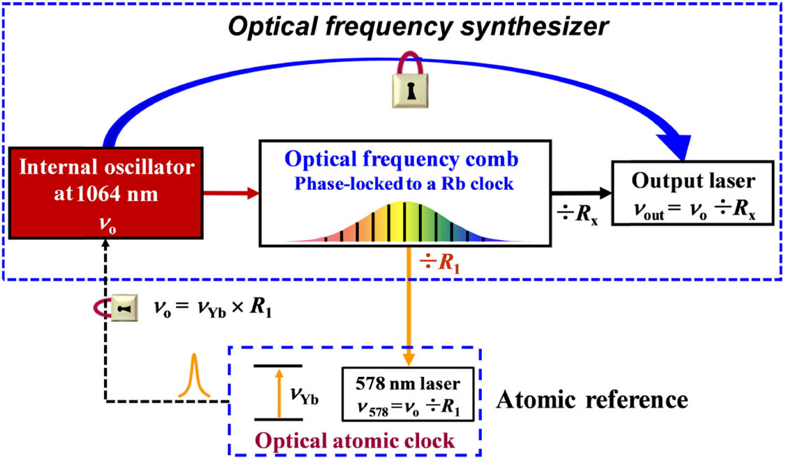
Similar to a microwave synthesizer, an OFS has an internal oscillator with low-frequency noise and good short-term frequency stability as shown in Fig. 1. The internal oscillator of our OFS described in this paper is a Nd:YAG laser at 1064 nm, which is frequency stabilized to a 10 cm long optical cavity with a laser frequency instability of at 1 s average time and a laser linewidth below 1 Hz [39]. The internal oscillator described here can be continuously running. Meanwhile, we can easily obtain a beat signal of the internal oscillator against an optical frequency comb with a signal-to-noise ratio better than 40 dB at a resolution bandwidth (RBW) of 300 kHz over days, ensuring the continuous running hours of the OFS.
Figure 1.Block diagram of an optical frequency synthesizer. An OFS includes an internal oscillator, an optical frequency comb, and output lasers. The internal oscillator is a cavity-stabilized laser at 1064 nm with a frequency instability of at 1 s averaging time. The comb is phase locked to the RF signals referenced to a Rb microwave clock. Using the comb combined with comb frequency noise-reduction techniques, the frequencies of the output laser and a 578 nm laser are accurately set. The phase-locked 578 nm laser is used to probe the clock transition of Yb atoms and then make the internal oscillator further referenced to the Yb atomic clock as .
The OFS also includes an optical frequency comb for frequency conversion and single-frequency output lasers with ample light power and frequency tunability. The output laser frequency of the OFS is accurately set at with the frequency of the OFS internal oscillator at 1064 nm and a preset divisor.
Since the frequency of the internal oscillator is not accurate and it drifts as well, the OFS is further referenced to the clock transition of Yb atoms with a servo bandwidth below 1 Hz. Here we transfer the frequency of the internal oscillator at 1064 nm to 578 nm as with a preset divisor. The target 578 nm laser is then used to probe the clock transition of Yb atoms. Any frequency deviation of from the Yb atomic resonance () will generate a correction signal, which is fed back to the OFS internal oscillator at 1064 nm to make . By further referencing the OFS to the Yb atomic clock as an atomic reference, the OFS acquires frequency stability in the long term as well as high frequency accuracy. Thereby, the output frequency of the OFS is accurately known as
3. LOW-NOISE OPTICAL FREQUENCY SYNTHESIS BASED ON A COMB PHASE LOCKED TO A RUBDIUM CLOCK
The optical frequency comb is the key element in OFS. The optical frequency comb described in this paper is based on a turnkey Ti:sapphire mode-locked femtosecond (fs) laser with a repetition rate (Laser Quantum), whose spectrum is broadened in a piece of photonic crystal fiber to an octave covering 530–1100 nm. The frequency of the th comb tooth is with the carrier-envelope offset frequency of the comb and , an integer. A collinear self-referencing setup [40] is employed to detect , while is obtained by detecting a portion of the fs laser light on a photodiode. The signals of and are phase locked to radio frequency (RF) signals referenced to a Rb microwave clock (SRS FS725) by adjusting the pumping power and the cavity length of the fs laser accordingly.
The comb can be continuously running while phase locked to the Rb clock. Figure 2(a) shows the fluctuation of and over five days when they are phase locked to the Rb clock. As we can see in the figure, and became noisier when there were disturbances due to human activities, but they remained locked. There are six cycle slips removed from the data of . Such an arrangement for the comb places less demand on the environment compared to that stabilized to an ultrastable laser. However, the frequency noise of the Rb clock is almost 5 orders of magnitude worse than that of an ultrastable laser, leading to noisier comb lines. The left panel of Fig. 2(b) shows the spectral distribution of a comb line near 1064 nm when compared against a subhertz-linewidth, cavity-stabilized laser at 1064 nm. The beat note reveals a comb linewidth on the order of megahertz (MHz). The blue triangles in Fig. 2(c) show the frequency instability of the beat note between the comb line at 1064 nm and the cavity-stabilized 1064 nm laser. On a short time scale it illustrates the frequency instability of the comb line, which is limited by the Rb clock, while above 1000 s averaging time it is limited by the frequency drift of the cavity-stabilized 1064 nm laser. It indicates that the frequency instability of the comb line is about at 1 s averaging time.
Figure 2.Performance of optical frequency synthesis using a comb phase locked to a Rb clock. (a) Frequency fluctuation of and when phase locked to RF signals referenced to the Rb clock. (b) Spectrum of the beat note between a comb line at 1064 nm and the cavity-stabilized laser at 1064 nm (left panel, RBW of 30 kHz). The spectrum of (right panel, RBW of 1 mHz and acquisition time of 1000 s). It shows a combined noise of optical frequency synthesis and SHG. (c) Fractional instability of a comb line (blue triangles), the most stable optical clocks (blue solid line), and (optical frequency synthesis noise) in terms of Allan deviation (i) when the comb is phase locked to the Rb clock, and optically self-referenced time base is used as the time base of and the counters (green dots); (ii) when the comb is phase locked to a cavity-stabilized laser, and the optically self-referenced time base is used (purple filled squares); and (iii) when the comb is phase locked to the Rb clock, and the Rb clock is used as the time base of and the counters (red open squares). (d) Experimental diagram to test the performance of optical frequency synthesis. The ratio is measured against set by the second-harmonic generation. PLL, phase-locked loop.
Although the frequency noise of the comb is more than 4 orders of magnitude higher than that of the internal oscillator and an optical clock, we combine the transfer oscillator scheme and the optically self-referenced time base to achieve low-noise optical frequency synthesis.
In the transfer oscillator scheme [35], two beat notes between the output laser , the internal oscillator , and their nearby comb lines are detected as where and are integers associated with the particular comb lines. The signal of is subtracted from and by mixing with the detected signal of . After mixing, the resulting signals are The outputs of the mixers are sent to two direct digital synthesizers (DDSs) with divisors and , respectively. The divisors and are chosen to satisfy Thereby, when the outputs of the two DDSs are compared on a third mixer, an error signal for phase-locking servo is generated as which is free from comb signals of and . Therefore, any frequency fluctuation of the comb line will not affect the performance of optical frequency synthesis. As long as is sent to a servo to adjust the output laser frequency to make , the output laser is phase locked to the internal oscillator, whose frequency is with preset by the DDSs. For convenience of precise tuning of , is mixed with a tunable signal on a mixer before mixing with . Thus, . In order to make independent of any additional frequency standard, here has to be related to only.
To make related to only, we use the beat signals and between and its two nearby comb teeth to obtain an optically self-referenced RF signal [29] with and as the divisors of another two DDSs, which are chosen to satisfy . The comb signals of and are subtracted from using the transfer oscillator scheme. Then the signal of is sent to a DDS to generate an optically self-referenced time base at 10 MHz as with , a known divisor related to and . Then is synthesized on an RF synthesizer from as with , a known divisor, and . The optically self-referenced time base makes , independent of any additional RF time base, and it reduces the synthesis noise (see below). As a result, the output laser frequency is accurately set as .
To characterize the synthesis noise and accuracy when the comb is phase locked to the Rb microwave clock, we compare the frequency ratio set by the comb against that set naturally by the second-harmonic generation (SHG), another kind of optical frequency synthesis based on a different working principle with divisor , to the precision we demonstrate [29,41]. As shown in Fig. 2(d), the frequency of a test laser at 532 nm () is preset as , where is set to 0.500 000 053 261 644 723 856. The frequency of is controlled by adjusting a piezo transducer (PZT) inside the fundamental light of the test laser at 1064 nm (). The beat signal between and is then detected and measured by a dead-time-free -type counter (), whose time base at a frequency of 10 MHz is the optically self-referenced time base . With the reading number from the counter, is measured to be while is also related to the setting divisors and as From Eqs. (15) and (16), the divisor can be indirectly measured as . In order to improve the measurement accuracy, is usually mixed down to several hundred kilohertz for counting [29].
The green dots in Fig. 2(c) show the fractional instability of , which is calculated based on 14 data sets with a total measurement time of nearly 165,000 s. All data sets are continuous with duration longer than 3000 s, containing no cycle slips. Additional frequency noises of at 1 s averaging time and at 1000 s are included in optical frequency synthesis, 6 orders of magnitude lower than that of the comb line (blue triangles). This measurement demonstrates that optical frequency synthesis is largely immune to the comb frequency noise. The optical frequency synthesis noise is about 7 times better than the frequency instabilities of the most stable optical clocks (shown with solid blue line) [13], supporting frequency synthesis of optical clocks without degrading their performance. The pink squares in Fig. 2(c) show the synthesis noise when the comb is phase locked to an ultrastable laser [29], which indicates that as the comb noise gets lower the synthesis noise gets lower. The red open squares in Fig. 2(c) show the synthesis noise when the time base of the synthesizer for adjusting is from the Rb clock. It is nearly 10 times higher than that using the optically self-referenced time base (), and it is larger than the frequency instability of the state-of-the-art optical clocks (blue solid line), which is less than ideal for frequency synthesis of optical clocks.
The right panel of Fig. 2(b) shows a spectrum of measured on an RF spectrum analyzer, representing the additional linewidth induced in optical frequency synthesis and SHG. The measured 2 mHz linewidth of is limited by the measurement acquisition time of 1000 s. It demonstrates that laser coherence can be faithfully transferred from the most stable optical oscillators, which are realized by stabilizing to cryogenic optical cavities [9,10], to desired target lasers.
The mean value of is calculated based on the above data sets. It is found to deviate from its set value by with an uncertainty of according to the Allan deviation of at an averaging time of . The described apparatus also enables frequency ratio measurement with uncertainties of in . The uncertainty in optical frequency synthesis is therefore 3 orders of magnitude better than that of the most accurate optical clocks [11–15], indicating that synthesizing clock frequencies to other desired frequencies is near perfectly carried out. All these results demonstrate that the described apparatus based on the comb phase locked to the Rb clock can transfer the coherence, frequency stability, and accuracy from optical oscillators or clocks to target lasers without degrading their performance.
4. OFS REFERENCED TO AN YTTERBIUM OPTICAL CLOCK
With the comb as well as the comb frequency noise-reduction techniques, frequencies and coherence can be directly transferred from the internal oscillator to a broad optical region of 530–1100 nm. Such an OFS provides light sources with high frequency stability and narrow linewidth for spectroscopy. However, the frequency of the internal oscillator is never perfectly accurate, and it drifts slowly with environmental temperature, leading to an unstable output light frequency. To solve this problem, we further reference the OFS to an Yb optical clock.
In the actual experiment, the spectral purity of the internal oscillator at 1064 nm is transferred to a laser at 578 nm as shown in Fig. 3(a). The frequency of the 578 nm laser is set as , with a preset and adjustable division ratio. Part of the 578 nm light is transferred via a polarization-maintaining fiber to the comb for optical frequency synthesis. Extra random phase noise arising from the optical fiber is suppressed with active fiber noise cancellation [42]. Benefiting from the low optical frequency synthesis noise, the 578 nm laser need not be prestabilized. As a result, the 578 nm laser inherits the coherence of the internal oscillator, expecting to have a linewidth of 1 Hz and a frequency instability of at 1 s averaging time.
Figure 3.OFS referenced to an Yb optical clock. (a) Experimental diagram. With a comb phase locked to a Rb clock, the coherence of the internal oscillator at 1064 nm is transferred to 578 nm for detecting the clock transition of Yb atoms. Any frequency deviation of the 578 nm laser from the atomic transition is fed back to to assure . A tunable single-frequency laser is employed as the output of the OFS, whose frequency is controlled to be . (b) Rabi spectrum of Yb clock transition (no averaging). Fourier-limited Rabi spectra with spectral linewidth of 4.1 Hz and 2 Hz (inset) are observed at interrogation times of 200 ms and 400 ms, respectively. (c) Fractional frequency instability of when referenced to the Yb clock based on an interleaved measurement.
The remaining part of the phase-locked 578 nm laser light is delivered to Yb atoms for spectroscopy via another piece of polarization-maintaining optical fiber with fiber noise cancelled. Laser cooling and trapping of Yb atoms is described in detail in Ref. [43] and is similar to other studies [5,44,45]. Atoms of isotope are slowed and trapped into a six-beam magneto-optical trap (MOT) on the transition at 399 nm with a linewidth of 28 MHz. They are further cooled in a second MOT on the transition at 556 nm with a narrower linewidth of 182 kHz. By the end of this second phase, the temperature of the atoms in the MOT is roughly 16 μK. Light from a Ti:sapphire continuous-wave laser light at 759 nm is focused by a lens and retroreflected by a curved mirror to form an optical lattice with a trap depth of ( is recoil energy) and a cross-section diameter of 110 μm. The lattice light beam is offset 5° along the vertical direction. The atom number and lifetime in the optical lattice are roughly and 4 s, accordingly. During state preparation, laser light at 556 nm optically pumps the atoms to either one of the two Zeeman substates. Three pairs of Helmholtz coils are employed to cancel the static stray magnetic field in three directions and to provide a bias magnetic field to split the nuclear spin state degeneracy. The light of is then combined with the lattice light on a dichroic mirror. The polarizations of the 578 nm laser light and the 759 nm lattice laser light are oriented along a bias magnetic field . After probing the clock transition of Yb atoms, the populations in the and the states are measured in sequence using shelving detection.
We obtain the Rabi spectrum of Yb atoms by stepping . With a 400 ms atomic interrogation time, 27 spectra of the transition with an average spectral linewidth of 2 Hz are obtained, demonstrating the ability of optical frequency synthesis for high-precision spectroscopy. The inset of Fig. 3(b) shows one of the spectra at the maximum excitation rate of only 0.5, mainly limited by the atomic coherence time. In order to obtain a maximum excitation rate of no less than 0.8 for laser stabilization, we keep the atomic probe time of 200 ms and a single cycle time of 550 ms. The red dots in Fig. 3(b) show a single-scan, normalized excitation spectrum with a Fourier-limited spectral linewidth of 4.1 Hz (full width at half-maximum, FWHM).
Based on the 4.1 Hz linewidth Rabi spectrum, we keep the 578 nm laser on resonance with the atomic transition () by adjusting the driving frequency of an acousto-optic modulator (AOM) placed between the 1064 nm laser and its reference cavity as shown in Fig. 3(a). The servo bandwidth is below 1 Hz, determined by the atomic cycle time. After referencing to the Yb optical clock, the frequency of the internal oscillator is .
To show how precisely the OFS is referenced to the Yb optical clock, we make a measurement by interleaving the clock operation with two independent frequency locks [5,37,46]. The frequency instability of shown in Fig. 3(c) is consistent with that of an optical atomic clock typically limited by the Dick effect [47] arising from limited atomic interrogation time and laser frequency noise of a probe light dominated by the thermal noise of a 10 cm long, room-temperature optical cavity.
The long-term frequency stability of our OFS is improved by referencing to the Yb optical clock, which is ultimately limited by the drift of systematic frequency shifts of the Yb optical clock. As long as the OFS is referenced to the Yb clock transition, the output frequency of the OFS can be accurately set as , where is the frequency ratio set as .
5. CONCLUSION
In summary, we develop and characterize an OFS referenced to an Yb optical clock. The total residual frequency instabilities during optical frequency synthesis based on the comb phase locked to the Rb clock are and at an averaging time of 1 s and 1000 s, respectively, which is at least 7 times better than that of the most stable optical clocks. The uncertainty in optical frequency synthesis is demonstrated to be , 3 orders of magnitude better than that of optical clocks. Such low-noise optical frequency synthesis enables us to synthesize the frequency from the OFS internal oscillator at 1064 nm to a laser operated at 578 nm and to resolve a 2 Hz linewidth spectrum of Yb clock transition. After further referencing the OFS to the clock transition of Yb atoms, we make an interleaved measurement showing a frequency instability of , consistent with Dick-effect-limited frequency stability of an optical clock using a 10 cm long cavity-stabilized probe laser. When the internal oscillator at 1064 nm is further improved, the OFS output laser frequency will become more stable. Certainly, the OFS described here can also be referenced to other optical clocks, such as Sr, Hg, , , , and . Such an OFS based on the Ti:sapphire mode-locked laser enables possibilities to output optical waves with excellent coherence, frequency stability, and accuracy in the region of 530–1100 nm for precision spectroscopy and measurement, supporting many cutting-edge applications of most optical clocks. In the near future, as the SI second is redefined based on the optical clocks, OFS will become an increasingly indispensable tool to meet the varied applications.
Acknowledgment
Acknowledgment. We thank Li You for valuable comments on this manuscript and Albrecht Bartels from Laser Quantum for prompt technical support on the turnkey Ti:sapphire mode-locked laser.
References
[1] J. A. Scheer, J. L. Kurtz. Coherent Radar Performance Estimation(1993).
[47] G. J. Dick. Local oscillator induced instabilities in trapped ion frequency standards. Proceedings of the 19th Annual Precise Time and Time Interval Systems and Applications Meeting, 133-147(1987).