• Chinese Physics B
  • Vol. 29, Issue 8, (2020)
Shu-Fa Li1 and Tao Zhu2、†
Author Affiliations
  • 1College of Electronics and Information Engineering, Guangdong Ocean University, Zhanjiang 524088, China
  • 2Beijing National Laboratory for Condensed Matter Physics and Institute of Physics, Chinese Academy of Sciences, Beijing 100190, China
  • show less
    DOI: 10.1088/1674-1056/ab9292 Cite this Article
    Shu-Fa Li, Tao Zhu. Giant interface spin-orbit torque in NiFe/Pt bilayers[J]. Chinese Physics B, 2020, 29(8): Copy Citation Text show less
    Schematic diagrams of effective spin-orbit fields (a) in the longitudinal configuration (I ∥ H) and (b) in the transverse configuration (I ⊥ H) of PHE measurements.
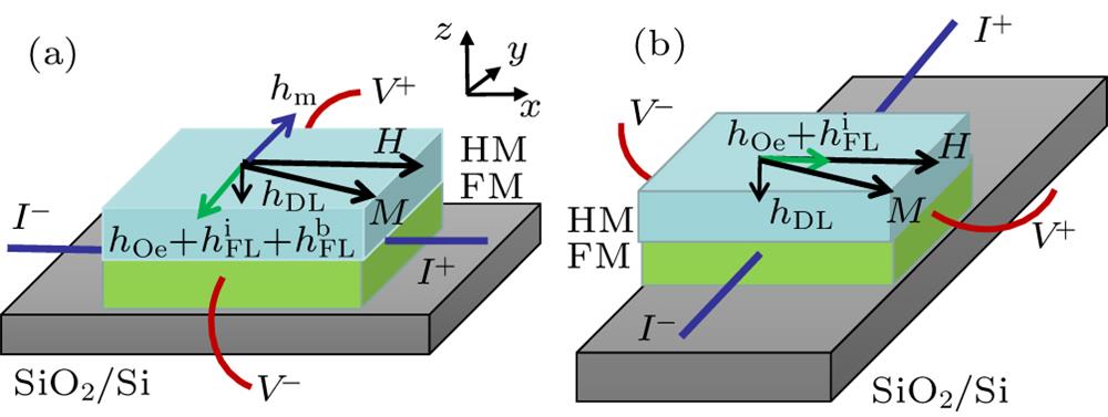
    Fig. 1. Schematic diagrams of effective spin-orbit fields (a) in the longitudinal configuration (IH) and (b) in the transverse configuration (IH) of PHE measurements.
    (a) The schematic of NiFe/Pt bilayer at the transverse configuration of the PHE measurement. The additional field of hx presents the effective field of the field-like SOT. (b) The field dependences of the resistance Rxy with various hx. The parameters in the simulation are given in text.
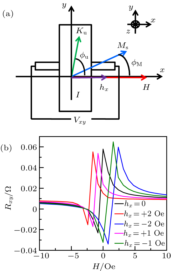
    Fig. 2. (a) The schematic of NiFe/Pt bilayer at the transverse configuration of the PHE measurement. The additional field of hx presents the effective field of the field-like SOT. (b) The field dependences of the resistance Rxy with various hx. The parameters in the simulation are given in text.
    The resistance and the effective field measured at the transverse PHE configuration (I ⊥ H) for NiFe(2.2)/Pt(3) bilayer. (a) The representative Rxy–H curves under various currents. In the inset, the solid lines are the fitting curves by using the Stoner–Wohlfarth model. (b) The current dependences of hx and the Oersted field hOe = I/2w, where w is the width of the Hall bar. The field hy was added here for comparison, which has been obtained at the longitudinal configuration.[25] (c) The current-dependent hFLi and hFLb. Here hFLi=hx−hOe and hFLb=hy−hx are the interfacial and bulk contributions to the effective fields of current-induced field-like SOT, respectively.
    Fig. 3. The resistance and the effective field measured at the transverse PHE configuration (IH) for NiFe(2.2)/Pt(3) bilayer. (a) The representative RxyH curves under various currents. In the inset, the solid lines are the fitting curves by using the Stoner–Wohlfarth model. (b) The current dependences of hx and the Oersted field hOe = I/2w, where w is the width of the Hall bar. The field hy was added here for comparison, which has been obtained at the longitudinal configuration.[25] (c) The current-dependent hFLi and hFLb. Here hFLi=hxhOe and hFLb=hyhx are the interfacial and bulk contributions to the effective fields of current-induced field-like SOT, respectively.
    Current dependences of (a) hFLi and (b) hFLb for the samples with various Pt thicknesses. The linear dependence of (c) hFLi and (d) hFLb on the current density j. All the solid lines are guides for the eyes.
    Fig. 4. Current dependences of (a) hFLi and (b) hFLb for the samples with various Pt thicknesses. The linear dependence of (c) hFLi and (d) hFLb on the current density j. All the solid lines are guides for the eyes.
    Shu-Fa Li, Tao Zhu. Giant interface spin-orbit torque in NiFe/Pt bilayers[J]. Chinese Physics B, 2020, 29(8):
    Download Citation