• High Power Laser and Particle Beams
  • Vol. 34, Issue 6, 063001 (2022)
Lei Lei1、2, Yu Zhou3, Dongping Gao1、2、*, and Quanju Shi1
Author Affiliations
  • 1Key Laboratory of High Power Microwave Sources and Technologies, Aerospace Information Research Institute, Chinese Academy of Sciences, Beijing 100190, China
  • 2School of Electronic, Electrical and Communication Engineering, University of Chinese Academy of Sciences, Beijing 100190, China
  • 3Chengdu Zhongdian Jinjiang Information Industry Co., Ltd., Chengdu 615000, China
  • show less
    DOI: 10.11884/HPLPB202234.210576 Cite this Article
    Lei Lei, Yu Zhou, Dongping Gao, Quanju Shi. Design of high efficiency forced air cooling heat dissipation system for collector of high-power klystron[J]. High Power Laser and Particle Beams, 2022, 34(6): 063001 Copy Citation Text show less
    Structure of air cooling collector
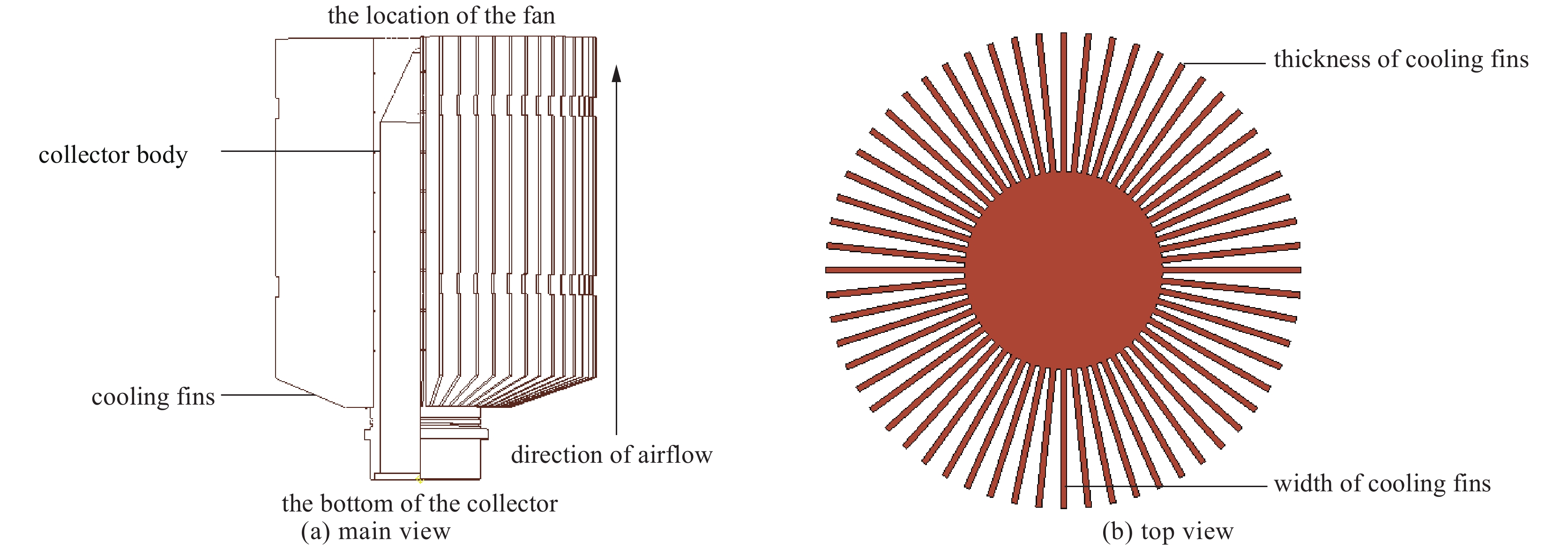
    Fig. 1. Structure of air cooling collector
    Characteristic curve of selected fan
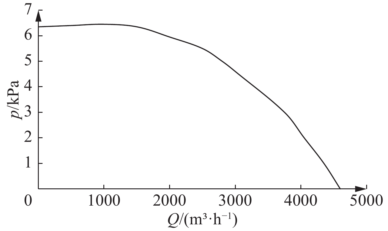
    Fig. 2. Characteristic curve of selected fan
    Effect of thickness, width and number of cooling fins on heat dissipation of collector
    Fig. 3. Effect of thickness, width and number of cooling fins on heat dissipation of collector
    Temperature distribution nephogram of collector under different heat dissipation modes
    Fig. 4. Temperature distribution nephogram of collector under different heat dissipation modes
    Temperature variation of cooling fins at different positions
    Fig. 5. Temperature variation of cooling fins at different positions
    Structure of collector with ventilation seat
    Fig. 6. Structure of collector with ventilation seat
    Effect of inner radius of duct on heat dissipation of collector
    Fig. 7. Effect of inner radius of duct on heat dissipation of collector
    Variation of wind speed in the duct without ventilation seat
    Fig. 8. Variation of wind speed in the duct without ventilation seat
    Variation of wind speed in the duct with ventilation seat
    Fig. 9. Variation of wind speed in the duct with ventilation seat
    Diagram of fan characteristic curve and duct characteristic curve
    Fig. 10. Diagram of fan characteristic curve and duct characteristic curve
    Distribution of wind resistance in duct
    Fig. 11. Distribution of wind resistance in duct
    Outline drawing of klystron
    Fig. 12. Outline drawing of klystron
    Temperature variation at root of cooling fins
    Fig. 13. Temperature variation at root of cooling fins
    T/℃ $ \rho $/(kg∙m−3) ${C}_{{\rm{p}}}$/(kcal·kg−1·℃−1) $\; \mu $/(kg∙m−1∙s−1)
    301.1650.2418.6×10−6
    Table 1. Physical parameters of air
    $ \mathit{K} $/mm2d/mm A/mm2$ {\mathit{A}}_{0} $/mm2L/mm
    669181332420612400
    Table 2. Structural parameters of air cooling collector system
    methodmaximum temperature/℃minimum temperature/℃mean temperature/℃
    experimental test191.655.4110.8
    simulation analysis195.253.8116.2
    Table 3. Comparison of experimental test and simulation analysis results
    Lei Lei, Yu Zhou, Dongping Gao, Quanju Shi. Design of high efficiency forced air cooling heat dissipation system for collector of high-power klystron[J]. High Power Laser and Particle Beams, 2022, 34(6): 063001
    Download Citation