• High Power Laser and Particle Beams
  • Vol. 35, Issue 4, 041002 (2023)
Bing He1, Binglin Li1、2, Yifeng Yang1, and Meizhong Liu1、2
Author Affiliations
  • 1Shanghai Key Laboratory of All Solid-State Laser and Applied Techniques, Shanghai Institute of Optics and Fine Mechanics, Chinese Academy of Sciences, Shanghai 201800, China
  • 2University of Chinese Academy of Sciences, Beijing 100049, China
  • show less
    DOI: 10.11884/HPLPB202335.220282 Cite this Article
    Bing He, Binglin Li, Yifeng Yang, Meizhong Liu. Coherent beam combining of fiber laser array based on diffractive optical element[J]. High Power Laser and Particle Beams, 2023, 35(4): 041002 Copy Citation Text show less
    Top-hatted beam with square and circlar beam profile
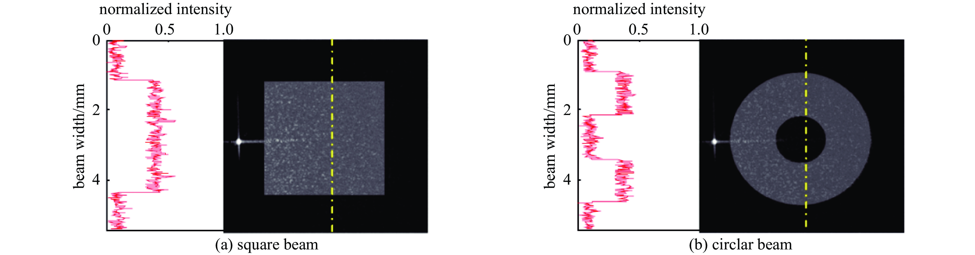
    Fig. 1. Top-hatted beam with square and circlar beam profile
    Schematic diagram of injection locking structure of binary grating coherent beam combining (CBC) technology co-cavity structure
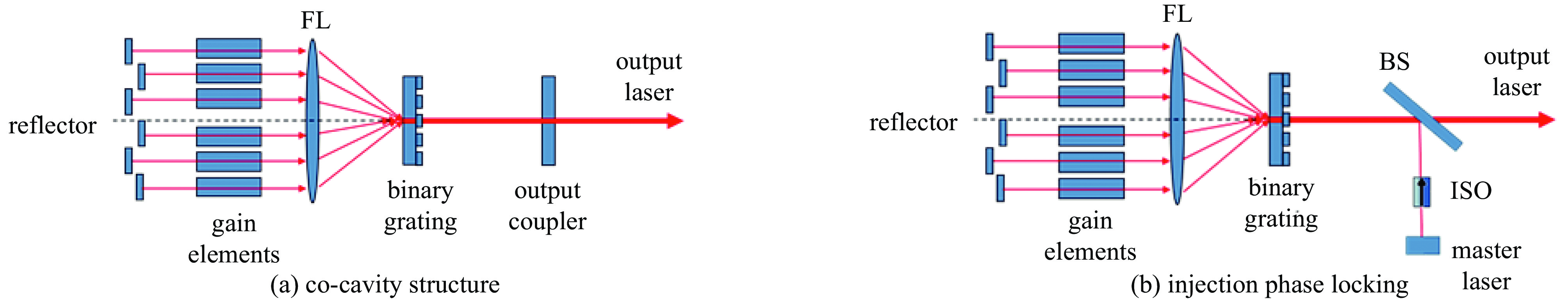
    Fig. 2. Schematic diagram of injection locking structure of binary grating coherent beam combining (CBC) technology co-cavity structure
    Basic principle and experimental setup of coherent beam combining of three-channel single-mode fiber lasers
    Fig. 3. Basic principle and experimental setup of coherent beam combining of three-channel single-mode fiber lasers
    Principle of coherent beam combining of semiconductor lasers based on Damman gratings
    Fig. 4. Principle of coherent beam combining of semiconductor lasers based on Damman gratings
    Experimental setup and spectrogram of passive coherent beam combining based on quantum cascade lasers (QCLs) and Dammann gratings
    Fig. 5. Experimental setup and spectrogram of passive coherent beam combining based on quantum cascade lasers (QCLs) and Dammann gratings
    All-optical feedback ring cavity experimental setup and experimental results
    Fig. 6. All-optical feedback ring cavity experimental setup and experimental results
    DOE-based active coherent beam combining system
    Fig. 7. DOE-based active coherent beam combining system
    Schematic diagram of DOE coherent beam combining
    Fig. 8. Schematic diagram of DOE coherent beam combining
    Two-dimensional DOE coherent beam combining system
    Fig. 9. Two-dimensional DOE coherent beam combining system
    Results of two-dimensional DOE coherent beam combining
    Fig. 10. Results of two-dimensional DOE coherent beam combining
    2.4 kW DOE coherent beam combining experiment structure diagram
    Fig. 11. 2.4 kW DOE coherent beam combining experiment structure diagram
    Structure diagram of 4.9 kW DOE coherent beam combining system
    Fig. 12. Structure diagram of 4.9 kW DOE coherent beam combining system
    Experimental setup of two-dimensional combination of four ultrashort pulsed beams using a diffractive optic pair
    Fig. 13. Experimental setup of two-dimensional combination of four ultrashort pulsed beams using a diffractive optic pair
    Experimental setup of 8-array ultrashort pulse diffraction coherent beam combining
    Fig. 14. Experimental setup of 8-array ultrashort pulse diffraction coherent beam combining
    Formation of the 5 × 5 uncombined beam array exiting DOE2, with a 3 × 3 incident beam array
    Fig. 15. Formation of the 5 × 5 uncombined beam array exiting DOE2, with a 3 × 3 incident beam array
    Experimental setup of deterministic stabilization of eight-way 2D diffractive beam combining using pattern recognition
    Fig. 16. Experimental setup of deterministic stabilization of eight-way 2D diffractive beam combining using pattern recognition
    SLM combiner experiment and hologram on SLM for generating 9×9 beams
    Fig. 17. SLM combiner experiment and hologram on SLM for generating 9×9 beams
    Structure of the neural network, with interference patterns (17×17) as input and the corresponding 81-beam phases array (9×9) as the output
    Fig. 18. Structure of the neural network, with interference patterns (17×17) as input and the corresponding 81-beam phases array (9×9) as the output
    Far-field interference pattern of three tiled aperture pulsed beamlets by an all-optical feedback loop
    Fig. 19. Far-field interference pattern of three tiled aperture pulsed beamlets by an all-optical feedback loop
    Measured pulse shape of the combined beam in five cycles
    Fig. 20. Measured pulse shape of the combined beam in five cycles
    yearinstitutionresultreference
    2008Northrop Grumman5 fiber lasers with 109 mW overall power, M2=1.04, combination efficiency is 91.4% [53]
    2012Massachusetts Institute of Technology5 fiber lasers with 1.93 kW overall power, M2=1.1, combination efficiency is 79% [54]
    2012Northrop Grumman15 fiber lasers with 600 W overall power, M2=1.1, combination efficiency is 68% [55]
    2014Northrop Grumman3 fiber lasers with 2.4 kW overall power, M2=1.2, combination efficiency is 80% [56]
    2016Air Force Research Laboratory5 fiber lasers with 4.9 kW overall power, M2=1.1, combination efficiency is 82% [57-58]
    Table 1. Representative research results of DOE CW CBC
    Yearinstitutionresultreference
    2014Shanghai Insititute of Optics and Fine Mechanics, Chinese Academy of Sciences channel number is 2; tp=9.6 ns; fp=2.2 MHz; Pp=1.02 kW; η=61% [64]
    2017Lawrence Berkeley National Laboratorychannel number is 4; tp=120 fs; fp=100 MHz; Pa=150 mW; η=83.4% [59]
    2018Lawrence Berkeley National Laboratorychannel number is 8; tp=120 fs; fp=100 MHz; η=85.4% [60]
    2019Lawrence Berkeley National Laboratorychannel number is 8; tp=100 fs; η=84.6% [61]
    2021Air Force Research Laboratorychannel number is 81; η=60.4% [62]
    Table 2. Representative research results of DOE pulse CBC
    Bing He, Binglin Li, Yifeng Yang, Meizhong Liu. Coherent beam combining of fiber laser array based on diffractive optical element[J]. High Power Laser and Particle Beams, 2023, 35(4): 041002
    Download Citation