• High Power Laser Science and Engineering
  • Vol. 4, Issue 2, 02000e16 (2016)
Stefano Bonora1, Jan Pilar2、3, Antonio Lucianetti2, and Tomas Mocek2
Author Affiliations
  • 1CNR-IFN, Via Trasea 7, 35131, Padova, Italy
  • 2HiLASE Centre, Institute of Physics AS CR, Za Radnic′? 828, 252 41 Doln′? Bˇreˇzany, Czech Republic
  • 3Department of Physical Electronics, Faculty of Nuclear Sciences and Physical Engineering, Czech Technical University in Prague,
  • show less
    DOI: 10.1017/hpl.2016.14 Cite this Article Set citation alerts
    Stefano Bonora, Jan Pilar, Antonio Lucianetti, Tomas Mocek. Design of deformable mirrors for high power lasers[J]. High Power Laser Science and Engineering, 2016, 4(2): 02000e16 Copy Citation Text show less
    (a) Slab of active media, (b) heat deposition distribution and thermal effects numerical model results in the form of resulting temperature and OPD distributions.
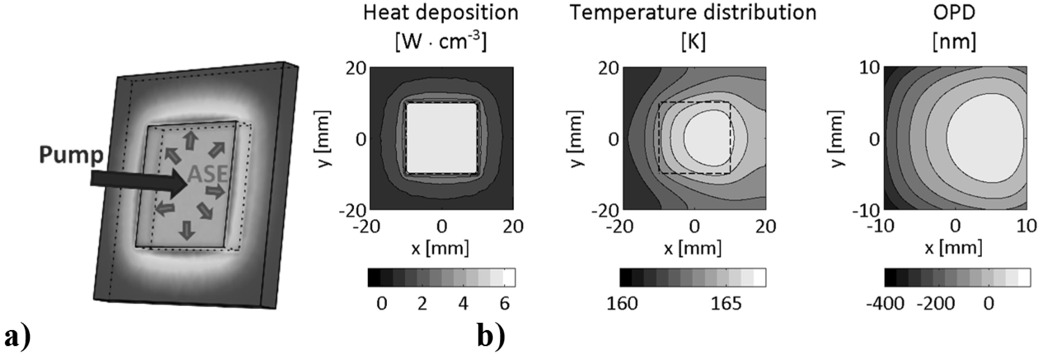
    Fig. 1. (a) Slab of active media, (b) heat deposition distribution and thermal effects numerical model results in the form of resulting temperature and OPD distributions.
    (a) Example of actuators position in a square DM. SA defines the size of the side actuators; AR is the size of the active region (part of the DM illuminated by the laser beam). (b) Reports the Strehl Ratio obtained with the correction of the DM realized in different configurations as reported in the legend in function of the DM stroke.
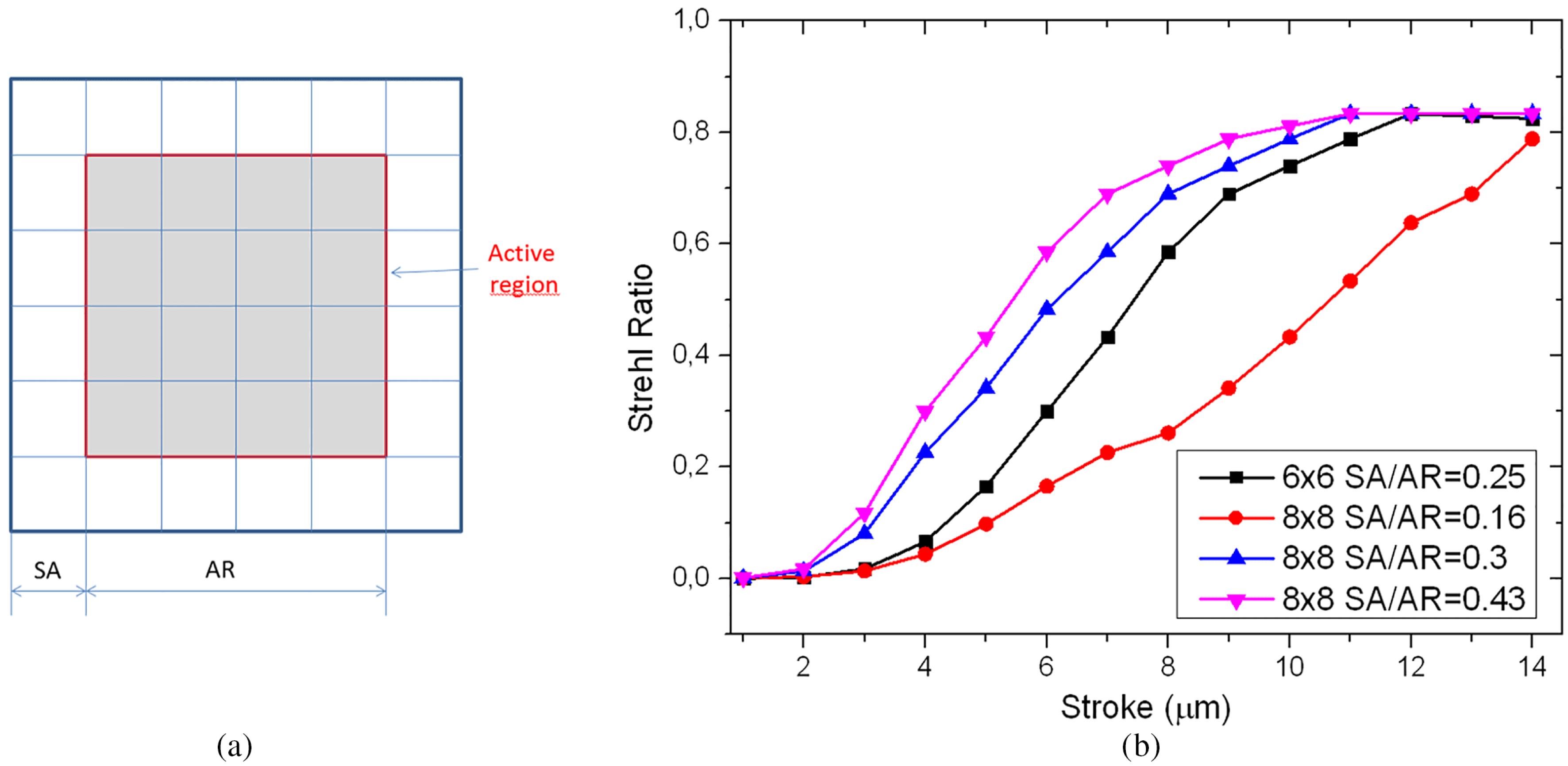
    Fig. 2. (a) Example of actuators position in a square DM. SA defines the size of the side actuators; AR is the size of the active region (part of the DM illuminated by the laser beam). (b) Reports the Strehl Ratio obtained with the correction of the DM realized in different configurations as reported in the legend in function of the DM stroke.
    Stroke in function of glass diameter (with fixed aspect ratio of 25) and PZT thickness with voltage held constant to 150 V.
    Fig. 3. Stroke in function of glass diameter (with fixed aspect ratio of 25) and PZT thickness with voltage held constant to 150 V.
    Pictures of the characterized DMs. (a) Dipole $6\times 6$, (b) HiLASE $7\times 7$, (c) HiLASE $6\times 6$ with the control box.
    Fig. 4. Pictures of the characterized DMs. (a) Dipole $6\times 6$, (b) HiLASE $7\times 7$, (c) HiLASE $6\times 6$ with the control box.
    Results of characterization of three DMs in terms of Legendre modes generation capability. The results are compared with the estimated Legendre decomposition of the wavefront of 10 J multi-slab amplifier, which was calculated by the Miró model.
    Fig. 5. Results of characterization of three DMs in terms of Legendre modes generation capability. The results are compared with the estimated Legendre decomposition of the wavefront of 10 J multi-slab amplifier, which was calculated by the Miró model.
    (a) Cross-section of the spot obtained with by the application of the wavefront calculated with the thermo-optical simulations and after the correction with the closed loop. (b) Spot image of the aberrated wavefront. (c) Spot after the correction with the closed loop operation.
    Fig. 6. (a) Cross-section of the spot obtained with by the application of the wavefront calculated with the thermo-optical simulations and after the correction with the closed loop. (b) Spot image of the aberrated wavefront. (c) Spot after the correction with the closed loop operation.
    Hilase DiPOLE Hilase $7\times 7$Femto1$\text{CO}_{2}$Femto45
    Mirror size ($\text{mm}^{2}$)$40\times 40$$30\times 30$$40\times 40$$36\times 36$40 mm10 cm
    Estimated beam size ($\text{mm}^{2}$)$27\times 27$$20\times 20$$26\times 26$$24\times 24$30 mm5 cm
    Actuator array disposition$6\times 6$$6\times 6$$7\times 7$$6\times 6$144 circular36 oval ($45^{\circ }$)
    Laser DPSSL DPSSL DPSSL Ti:Sa$\text{CO}_{2}$Ti:Sa
    Reflectivity bandwidth (nm)960–1120960–1120960–1120 710–880 780–820
    Reflectivity${>}$99.9%${>}$99.9%${>}$99.9%${>}$99.99%${>}$99.9%
    Dispersion$\text{GDD}<20~\text{fs}^{2}$$\text{GDD}<20~\text{fs}^{2}$
    CoatingDielectricDielectricDielectricDielectric GoldDielectric
    Damage threshold ($\text{J}/\text{cm}^{2}$)${>}20$${>}20$${>}20$${>}5$${>}5$
    SA/RA 0.24 0.25 0.26 0.25 0.16 0.21
    Table 1. Parameters of the characterized DMs.
    Stefano Bonora, Jan Pilar, Antonio Lucianetti, Tomas Mocek. Design of deformable mirrors for high power lasers[J]. High Power Laser Science and Engineering, 2016, 4(2): 02000e16
    Download Citation