• Photonics Research
  • Vol. 10, Issue 9, 2133 (2022)
Qiuyan Li1, Sheng Cao1、2、*, Peng Yu1, Meijing Ning1, Ke Xing1, Zhentao Du1, Bingsuo Zou1, and Jialong Zhao1、3、*
Author Affiliations
  • 1School of Physical Science and Technology, MOE Key Laboratory of New Processing Technology for Non-ferrous Metals and Materials, Guangxi Universityhttps://ror.org/02c9qn167, Nanning 530004, China
  • 2e-mail: caosheng@gxu.edu.cn
  • 3e-mail: zhaojl@ciomp.ac.cn
  • show less
    DOI: 10.1364/PRJ.467604 Cite this Article Set citation alerts
    Qiuyan Li, Sheng Cao, Peng Yu, Meijing Ning, Ke Xing, Zhentao Du, Bingsuo Zou, Jialong Zhao. Boosting electroluminescence performance of all solution processed InP based quantum dot light emitting diodes using bilayered inorganic hole injection layers[J]. Photonics Research, 2022, 10(9): 2133 Copy Citation Text show less

    Abstract

    The development of high-performance InP-based quantum dot light-emitting diodes (QLEDs) has become the current trend in ecofriendly display and lighting technology. However, compared with Cd-based QLEDs that have already been devoted to industry, the efficiency and stability of InP-based QLEDs still face great challenges. In this work, colloidal NiOx and Mg-doped NiOx nanocrystals were used to prepare a bilayered hole injection layer (HIL) to replace the classical polystyrene sulfonate (PEDOT:PSS) HIL to construct high-performance InP-based QLEDs. Compared with QLEDs with a single HIL of PEDOT:PSS, the bilayered HIL enables the external quantum efficiencies of the QLEDs to increase from 7.6% to 11.2%, and the T95 lifetime (time that the device brightness decreases to 95% of its initial value) under a high brightness of 1000 cd m-2 to prolong about 7 times. The improved performance of QLEDs is attributed to the bilayered HIL reducing the mismatched potential barrier of hole injection, narrows the potential barrier difference of indium tin oxide (ITO)/hole transport layer interface to promote carrier balance injection, and realizes high-efficiency radiative recombination. The experimental results indicate that the use of bilayered HILs with p-type NiOx might be an efficient method for fabricating high-performance InP-based QLEDs.

    1. INTRODUCTION

    Quantum dot light-emitting diodes (QLEDs) have been regarded as one of the most promising alternatives for the next generation of display and lighting devices because of their high photoluminescence quantum yield (PL QY), size-controllable emission wavelength, and simple solution processability [19]. At present, the QLEDs based on CdSe and perovskite quantum dots (QDs) have greatly improved, and their performance can be comparable to the commercial organic light-emitting diodes (OLEDs) [1014]. However, according to the “Restriction of Hazardous Substances Directive”, the inherent toxicity of Cd/Pb might inhibit their further development. Indium phosphide (InP) QDs have become the most promising benign substitute for heavy metal-free emitters due to their excellent luminescence properties [1519]. Although some breakthroughs have been achieved in the electroluminescence (EL) of InP-based QLEDs through continuous efforts and attempts, their performance is still falling behind those of Cd- and Pb-based QLEDs [10,11,15,19]. Therefore, it is necessary to exploit highly efficient InP-based QLEDs with considerable stability for future display applications.

    To improve the efficiency and stability of InP-based QLEDs, researchers focused on synthesizing high PL QY InP QDs and modifying the device structures [15,19]. However, it should be noted that almost all reports of InP-based QLEDs are using polystyrene sulfonate (PEDOT:PSS) as the hole injection layer (HIL) at present [17,2022]. The water-based PEDOT:PSS dispersion has side effects on the stability of QLEDs due to its hygroscopicity and the acidity that corrodes the indium tin oxide (ITO) electrode, thus shortening the lifetime of QLEDs [23]. It is reported that p-type metal oxide (NiOx) has been developed as HIL of Cd-based QLEDs due to its inherent environmental stability and high carrier mobility [2427]. In particular, the high work function (WF) and wide bandgap of NiOx can provide excellent contact for hole injection and an energy barrier for blocking electrons. Therefore, the development of InP-based QLEDs based on NiOx HIL is expected to be an efficient way to improve the efficiency and stability of InP-based QLEDs, although there is still a lack of reports in this regard.

    The balance between electron and hole injection into the QD emission layer is significant to acquire high-performance QLEDs [18,2830]. Due to the deep valence band (VB) of QDs, hole injection is generally more difficult than electron injection because of the higher injection barrier [3]. The use of bilayered HIL is a good way to reduce the energy barrier at each step. Scientists have conducted research in the field of OLEDs to improve their efficiency [12,13]. However, the multilayered HIL for QLEDs, especially the multilayered HIL around all inorganic materials, has rarely been studied. It is also reported that the electronic properties of NiOx are highly dependent on its preparation method and postdeposition treatment, which can help us to adjust the WF and hole mobility in NiOx to regulate the hole injection behavior in QLEDs [24,25]. In particular, the recently reported film preparation technology of colloidal NiOx nanocrystals (NCs) can avoid the metal oxide HIL’s expensive vacuum deposition equipment [26,31]. Therefore, exploring the interface engineering between ITO electrode and multilayer NiOx the HIL is expected to regulate the induced carrier transport change of EL performance and improve the stability of InP-based QLEDs.

    In the present work, we report bilayered HIL InP-based QLEDs prepared by solution processing of colloidal NiOx and Mg-doped NiOx (Mg-NiOx) NCs. The all-inorganic bilayered HIL is expected to reduce the mismatched potential barrier of hole injection, lower the potential barrier difference of the ITO/hole transport layer (HTL) interface, and promote carrier balance injection for efficient radiative recombination. As a result, the typical QLEDs with a bilayered HIL show an external quantum efficiency (EQE) of 11.2% and a T95 lifetime of 3.6 h at 1000  cdm2, which is much higher than the EQE of 7.6% and T95 lifetime of 0.5 h of QLED with classical HIL of PEDOT:PSS. The approach of using bilayered HIL with p-type NiOx can be an efficient method for the implementation of high-performance InP-based QLEDs.

    2. EXPERIMENTAL DETAILS

    A. Materials

    Zn(OAc)2·2H2O, Mg(OAc)2·4H2O, Ni(NO3)2·6H2O, dimethyl sulfoxide (DMSO), potassium hydroxide, tetramethylammonium hydroxide (TMAH), ethanolamine, and ethylacetate were purchased from Aladdin. Poly(3,4-ethylenedioxythiophene):poly(styrene-sulfonate) (PEDOT:PSS 4083), 2, 3, 6, 7, 10, 11-hexaazatriphenylene-hexacabonitrile (HAT-CN), N,N’-bis(3-methylphenyl)-N,N’-bis(phenyl)-benzidine (poly-TPD) were obtained from Xi’an Polymer Light Technology, China. Red InP/ZnS QDs with a PL emission peak of 626 nm and 86% PL QY were obtained from Suzhou Xingshuo Nanotech Co., Ltd.

    B. Synthesis of NiOx and Mg-Doped NiOx NCs

    The colloidal NiOx and Mg-NiOx NCs were synthesized according to the work previously reported by Wang et al. [25]. Ni(NO3)2·6H2O (9 mmol) and dimethylene (90 mL) were charged into a three-necked round-bottom flask with vigorous stirring. Meanwhile, an ethanol solution of potassium hydroxide (28.35 mL, 0.4  molL1) was added dropwise, and the reaction was carried out at room temperature for 0.5 h to obtain a green precipitate, which was washed with ethanol, poured into dimethyl sulfoxide (120 mL), and refluxed at 160°C without inert gas protection for 3 h. The synthesized NCs were purified with ethanol and ethyl acetate. Then 0.15 mmol of ethanolamine was added to stabilize the NCs and finally, the dark gray sample was redispersed in deionized water for further use. Mg-NiOx NCs were prepared similarly by adding the desired stoichiometric amount of a mixture of Ni(NO3)2·6H2O and Mg(OAc)2·4H2O to a dimethyl sulfoxide solution dispersed in ethanol.

    C. Synthesis of Mg-Doped ZnO NCs

    40 mL of DMSO was combined with 8.5 mmol of Zn(OAc)2·2H2O and 1.5 mmol of Mg(OAc)2·4H2O in a reactor. The reactor was injected dropwise with a solution of 10 mmol TMAH diluted in 10 mL ethanol. The reaction mixture was then kept at 4°C for 1 h. Ethyl acetate was used to precipitate the NCs, which were then totally redispersed in ethanol [32].

    D. Fabrication of QLEDs

    The QLEDs were fabricated based on the structure of the ITO/HIL layers (PEDOT:PSS, Mg-NiOx, and NiOx/Mg-NiOx)/poly-TPD/QDs/ZnMgO/Al, respectively. ITO glasses were ultrasonically cleaned for 30 min using washing water, deionized water, acetone, and isopropanol. Except for the Al cathode, all these layers were spin-coated onto ITO glasses. PEDOT:PSS, NiOx, Mg-NiOx, poly-TPD, QDs, and ZnMgO, all were spin-coated onto ITO glasses at 3000r/min for 40 s and were heated at 130°C, 100°C, 100°C, 130°C, 80°C, 80°C for 15, 10, 10, 20, 5, 10 min. Finally, the devices were transformed into a vacuum coating machine under a vacuum level of 5×10⁴  Pa for the deposition of Al cathode with a speed of 1 nm/s. All devices were encapsulated in the glove box through commercially available ultraviolet-curable resin for further characterization. The cross-sectional scanning electron microscope image of the typical QLEDs shows that the thicknesses of the NiOx/Mg-NiOx, poly-TPD, QD, and ZnMgO layers were 50, 30, 20, and 70 nm, respectively.

    The hole-only device with a structure of the ITO/HIL layers (PEDOT:PSS, Mg-NiOx, and NiOx/Mg-NiOx)/poly-TPD/QDs/HAT-CN (10 nm)/Al (100 nm), respectively, and the electron-only device with a structure of ITO/ZnMgO/QDs/ZnMgO/Al (100 nm) were fabricated to compare the injection efficiency of holes and electrons.

    E. Characterization

    The transmission electron microscope (TEM) images were obtained using a JEOL JEM 2100PLUS microscope working at 200 kV. The X-ray diffraction (XRD) was measured using a CuKα (λ=1.5405) radiation rotating anode and an X-ray diffractometer (SMARTLAB 3 kW). The X-ray photoelectron spectroscopy (XPS) and ultraviolet photoelectron spectroscopy (UPS) measurements were performed by an X-ray photoelectron spectrometer (ESCALAB 250XI+). Ultraviolet−visible absorption spectra were recorded on a PerkinElmer Instruments, Lambda 750. PL spectra, and PL QY of QDs dispersed in hexane were characterized by Horiba Fluorolog-3 systems. Atomic force microscope (AFM) measurement was carried out with MVI Vista-IR. The current density-voltage characteristics for the QLED devices were measured using a Keithley 2400 source meter. The EL spectra were measured using a spectrometer (Ocean Optics, QE65000) and a Keithley 2400 source meter. The capacitance-voltage (C-V) test was conducted at room temperature by using Keithley 4200A-SCS, and the frequency and amplitude of the AC signal were 1000 Hz and 0.1 V, respectively. Impedance spectra were tested at 2.6 V using the AUTOLAB PGSTAT204 electrochemical workstation.

    3. RESULTS AND DISCUSSION

    The bilayered HILs were prepared by solution processing of colloidal NiOx and Mg-NiOx NCs. It has the advantages of low cost, low temperature, and simplicity, compared with sputtering and precursor combustion methods. Herein, doping Mg into NiOx is used to regulate their WF and electrical properties [25,33]. The concentration of Mg is 5% in our work, which referred to the recent work [25]. The sizes of NiOx and Mg-NiOx NCs are 3.63 and 3.37 nm, respectively, as determined by TEM. Meanwhile, XRD patterns show that NiOx and Mg-NiOx NCs have bornite NiO structures [Fig. 1(a)], which match well to the rock salt structured NiO (JSPDS card No. 65–2901). To confirm the elemental compositions, XPS was also performed. The obvious Mg 1s peak at 1302.8 eV appearing in Mg-NiOx NC film [Fig. 1(b)] confirms the existence of the Mg element while the NiOx shows no corresponding signal. Figures 1(c) and 1(d) show the Ni 2p and O 1s spectra of NiOx and Mg-NiOx films. The fitted Ni 2p and O 1s spectra of NiOx and Mg-NiOx both show double characteristic peaks, which are located at 853.8, 855.4, 529.1, and 530.9 eV, respectively, indicating the existence of Ni2+ and Ni3+ states in NiOx and Mg-NiOx NC films. Ni 2p and O 1s fitting spectra show that the ratio of Ni3+/Ni2+ in Mg-NiOx is lower than that in NiOx films, indicating that Mg doping can be used to regulate the conductivity of NiOx NCs [34].

    Structure, optical bandgap, and energy level of NiOx and Mg-NiOx NC films. (a) XRD patterns; (b)–(d) XPS spectra of (b) Mg 1s, (c) O 1s, and (d) Ni 2p; (e) Tauc plot; (f) UPS spectra.

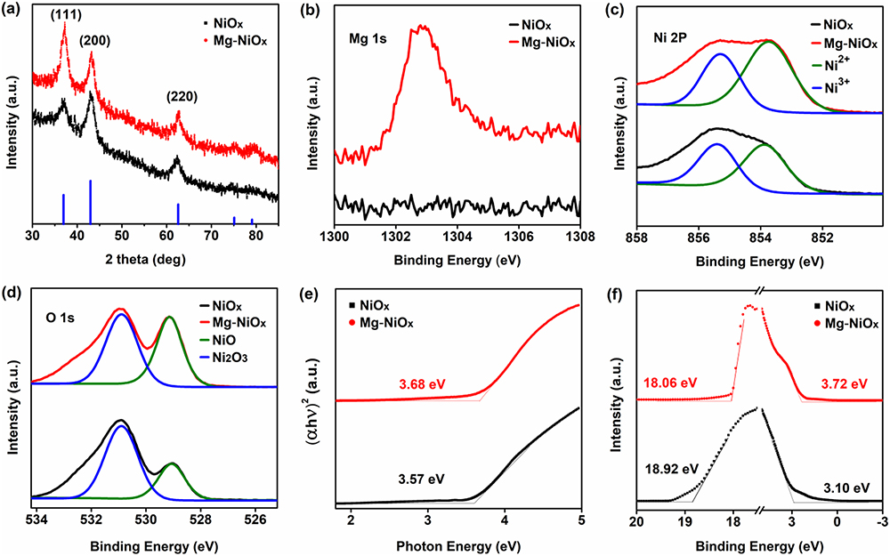
    Figure 1.Structure, optical bandgap, and energy level of NiOx and Mg-NiOx NC films. (a) XRD patterns; (b)–(d) XPS spectra of (b) Mg 1s, (c) O 1s, and (d) Ni 2p; (e) Tauc plot; (f) UPS spectra.

    While the energy levels of the solution-processed NiOx and Mg-NiOx NC films are significant to the performance of QLEDs, the UV–VIS absorption and UPS spectra were used. The optical bandgaps of these films were calculated using the extrapolation of the Tauc plot in Fig. 1(e), indicating that the optical bandgaps of NiOx and Mg-NiOx are 3.57 and 3.68 eV, respectively. According to the UPS spectra in Fig. 1(f), the valence-band maximum (VBM) of these films was calculated with the following equation: VBM=hν(EcutoffEonset), where the Eonset is the onset energy in the VB region and the Ecutoff represents the high cutoff binding energy [8]. The calculated VBM positions of NiOx and Mg-NiOx NC films were 5.20 and 5.44  eV, respectively. Furthermore, the conduction-band minimum (CBM) was calculated with the value of VBM and the bandgap obtained from the absorption spectra. The as-calculated CBM positions of NiOx and Mg-NiOx were 1.63 and 1.76  eV, respectively. The above results indicate that doping Mg into NiOx NCs can be used to regulate their energy level position, and then to design high-performance InP-based QLEDs.

    The surface morphology and optical transmittance of the HIL film prepared by solution processing are very important to the properties of QLEDs. Figures 2(a)–2(c) show AFM images of NiOx, Mg-NiOx, and NiOx/Mg-NiOx NC films, respectively. As shown in the figure, the root mean square (RMS) surface roughness of NiOx, Mg-NiOx, and NiOx/Mg-NiOx NC films is 3.66, 3.55, and 2.56 nm, respectively. The decrease of the roughness of the bilayered NiOx/Mg-NiOx NC film may be caused by the filling of the pores on the surface of the lower layer by the NCs in the upper layer. The bilayered NC film treated by solution can improve the uniformity of the film, which is expected to inhibit the leakage current of devices in QLED applications [35]. The optical transmittance of PEDOT:PSS and NiOx/Mg-NiOx NC bilayered HIL film was measured by the UV-VIS spectrophotometer. As shown in Fig. 2(d), the film shows high transmittance in the whole visible wavelength region. In particular, at the PL emission peak of 626 nm of InP QDs used in our study, the transmittance of PEDOT:PSS and NiOx/Mg-NiOx NC film is 83.8% and 84.3%, respectively. Compared with PEDOT:PSS HIL film, the bilayered NiOx/Mg-NiOx HIL has higher transmittance due to the multilayer optical interference effect [36]. The above results show that NiOx/Mg-NiOx NC films prepared by solution processing are uniform and compact and have excellent visible light transmittance, which is suitable for preparing InP-based QLEDs.

    (a)–(c) AFM images of the (a) ITO/NiO, (b) ITO/Mg-NiOx, and (c) ITO/NiOx/Mg-NiOx NC films; (d) transmittances of PEDOT:PSS and NiOx/Mg-NiOx HIL films deposited on the ITO substrate.

    Figure 2.(a)–(c) AFM images of the (a) ITO/NiO, (b) ITO/Mg-NiOx, and (c) ITO/NiOx/Mg-NiOx NC films; (d) transmittances of PEDOT:PSS and NiOx/Mg-NiOx HIL films deposited on the ITO substrate.

    To investigate effect of the bilayered HIL on the EL performance in the devices, the QLEDs were constructed with a typical structure of ITO/NiOx/Mg-NiOx NCs HIL/N,N’-bis(3-methylphenyl)-N,N’-bis(phenyl)-benzidine (poly-TPD) HTL/QDs/ZnMgO/Al, as shown in Fig. 3(a). All layers were spin-coated on the ITO substrate except for the Al cathode, which was deposited by vacuum thermal evaporation. The energy level diagram of QLED is shown in Fig. 3(b), while those NiOx and Mg-NiOx NCs have been described in detail in Figs. 1(e) and 1(f). The VBM and CBM of InP and ZnMgO were calculated from tests to be 5.66, 7.00, 3.74, and 3.56  eV, respectively. The typical EL spectrum of the device is shown in Fig. 3(c). It is found that the EL peak at 629 nm with a full width at half-maximum (FWHM) of 46 nm, which is consistent with the contrast QLEDs with the single HIL of PEDOT:PSS and Mg-NiOx.

    (a) Schematic of the layers in the device structure; (b) energy level diagram of the devices; (c) normalized EL spectra of devices. The inset shows a photograph of a device. (d) Luminance–voltage–current density (L–V–J) characteristics of QLEDs; (e), (f) EQE and CE as a function of luminance; (g) lifetime measurements at the initial luminance of 1000 cd m−2 of three typical QLEDs; (h) histogram of peak EQEs of NiOx/NiMgOx QLEDs obtained from 50 devices; (i) histogram of accelerated T95 lifetimes with an initial luminance of 1000 cd m−2 estimated from 1/2 of the total number of QLEDs based on a bilayered HIL of NiOx/Mg-NiOx.

    Figure 3.(a) Schematic of the layers in the device structure; (b) energy level diagram of the devices; (c) normalized EL spectra of devices. The inset shows a photograph of a device. (d) Luminance–voltage–current density (LVJ) characteristics of QLEDs; (e), (f) EQE and CE as a function of luminance; (g) lifetime measurements at the initial luminance of 1000  cdm2 of three typical QLEDs; (h) histogram of peak EQEs of NiOx/NiMgOx QLEDs obtained from 50 devices; (i) histogram of accelerated T95 lifetimes with an initial luminance of 1000  cdm2 estimated from 1/2 of the total number of QLEDs based on a bilayered HIL of NiOx/Mg-NiOx.

    Figure 3(d) shows the current density–luminance–voltage (J-L-V) characteristic of QLED devices. As shown in the figure, the turn-on voltage of devices with bilayered HIL is 2.0 V, which is lower than that of devices with a single HIL of PEDOT:PSS (2.1 V) and Mg-NiOx (2.1 V). In addition, it is also found that the current density and brightness of devices using PEDOT:PSS, Mg-NiOx, and NiOx/Mg-NiOx HILs increase in turn, and the maximum brightness reaches 7519, 9704, and 29,445  cdm2, respectively. Figures 3(e) and 3(f) show EQE and current efficiency (CE) as a function of the luminance of QLEDs. It was found that the maximum EQE of the devices with HIL of PEDOT:PSS, Mg-NiOx, and NiOx/Mg-NiOx is 7.6%, 8.1%, and 11.2%, respectively. Note that the NiOx/Mg-NiOx bilayered HIL device maintains high efficiency (EQE>10%) in the brightness range of 102104  cdm2, which can meet the standard of luminance of display and lighting. The working stability of these devices was further tested at 1000  cdm2 brightness. As shown in Fig. 3(g), the T95 lifetime of the device with the HIL of PEDOT:PSS, Mg-NiOx, and NiOx/Mg-NiOx is 0.5, 1, and 3.6 h, respectively. The EL performances of devices with different structures are summarized in Table 1. The high efficiency and good stability of NiOx/Mg-NiOx bilayered HIL devices show excellent reproducibility [Figs. 3(h) and 3(i)]. The above results show that the solution-processed inorganic NiOx/Mg-NiOx bilayered HIL can effectively improve the efficiency and stability of the InP-based QLED devices.

    Summary of EL Performances of Devices with Different Structures

    Device Structureλmax (nm)FWHM (nm)CE (cd  A1)EQE (%)Lmax(cdm2)
    ITO/PEDOT:PSS/poly-TPD/QDs/ZnMgO/Al629469.97.67519
    ITO/Mg-NiOx/poly-TPD/QDs/ZnMgO/Al6294610.68.19704
    ITO/NiOx/Mg-NiOx/poly-TPD/QDs/ZnMgO/Al6294615.411.229,445

    To understand the change in carrier transport properties caused by the NiOx/Mg-NiOx bilayered HIL in QLEDs, the corresponding VB energy levels of individual single and bilayered HIL devices are illustrated in Figs. 4(a)–4(c). The high electron mobility of ZnMgO leads to a large number of electrons being injected into the QD layer and accumulated at the poly-TPD/QD interface, resulting in an unbalanced injection of electrons and holes. The excess electrons will react electrochemically with the QDs to produce negatively charged states, reducing the radiative recombination rate and degrading the device performance. For the Mg-NiOx single-layered HIL device [Fig. 4(b)], the high mobility of the metal oxide promotes the hole injection, which allows more electrons and holes to compound, thereby reducing the negative electric state QD. For the bilayered HIL device [Fig. 4(c)], compared with the single-layered HIL device, the bilayered structure reduces the potential barrier that promotes hole injection and alleviates the accumulation caused by electron over-injection, thus balancing the charge injection and increasing the probability of radiative recombination to improve the performance of devices. Further, the J-V characteristics of electron-only devices and the hole-only device were measured to reveal the change in carrier transmission characteristics. As shown in Fig. 4(d), it can be observed that the current densities gradually increase in hole-only devices with the structure of PEDOT:PSS, Mg-NiOx, or NiOx/Mg-NiOx, and gradually approach the injection capacity of the electron-only device. These results demonstrated that the design and use of a bilayered HIL are conducive to hole injection. In general, over-injection of carriers in QLED will lead to charge accumulation and increased capacitance, so it can be detected by measuring the capacitance-voltage (C-V) characteristics of the device. As shown in Fig. 4(e), at relatively small applied voltages (0–1 V), the geometric capacitance of the three devices is almost the same. When the voltage is higher than 1 V, the capacitance of the three devices increases. In particular, the capacitance of bi-HIL devices rises faster than PEDOT:PSS and Mg-NiOx devices. It has been reported that the more carriers are injected into the device, the faster the capacitance rises. Because these devices have the same electron injection device structure, the faster capacitance rise of bilayered HIL devices can only be explained by enhancing hole injection. At the same time, the highest capacitance (3.1  nF ) and the corresponding voltage (2.1  V) of the bilayered HIL device are the lowest among the three devices, which indicates that the hole injection barrier is low and the recombination rate is high in this bilayered HIL device [37,38]. The impedance spectra [Fig. 4(f)] show the resistance of the QLEDs with the structure of PEDOT:PSS, Mg-NiOx, NiO/Mg-NiOx decreases gradually. It has been reported that the resistance of QLED is inversely proportional to the device recombination rate, the lower the composite resistance and the higher the recombination rate [39]. The result indicates that the bilayered HIL QLED also has the highest hole-electron recombination rate. Therefore, the above high EQE and stability of QLED devices based on NiOx/Mg-NiOx can be attributed to the improved carrier balance by the introduction of the bilayered HIL.

    (a)–(c) Charged QD− states, charge transport mechanisms, and hole injection barriers of the (a) PEDOT:PSS, (b) Mg-NiOx, and (c) NiOx/Mg-NiOx HIL devices; (d) J-V characteristic curves of the hole-only devices and electron-only devices for the three kinds of HILs of PEDOT:PSS, NiOx, and NiOx/Mg-NiOx; (e) C-V characteristics and (f) impedance spectra of InP-based QLED with HILs of PEDOT:PSS, NiOx, and NiOx/Mg-NiOx.

    Figure 4.(a)–(c) Charged QD states, charge transport mechanisms, and hole injection barriers of the (a) PEDOT:PSS, (b) Mg-NiOx, and (c) NiOx/Mg-NiOx HIL devices; (d) J-V characteristic curves of the hole-only devices and electron-only devices for the three kinds of HILs of PEDOT:PSS, NiOx, and NiOx/Mg-NiOx; (e) C-V characteristics and (f) impedance spectra of InP-based QLED with HILs of PEDOT:PSS, NiOx, and NiOx/Mg-NiOx.

    4. CONCLUSION

    The potential barrier of hole injection is large due to the low VB energy level of QDs, and the resulting charge balance difference is a typical feature of QLEDs. To alleviate the imbalanced charge injection, we introduced the NiOx/Mg-NiOx bilayered HIL formed by low-temperature solution processing of colloidal NCs to fabrication of high-performance InP-based QLEDs. The EQE and the maximum brightness of the as-fabricated device are 11.2% and 29,445  cdm2, respectively. The T95 lifetime at 1000  cdm2 reached 3.6 h, almost 7 times as long as the PEDOT:PSS-based device. The above high EQE and stability of QLED devices based on NiOx/Mg-NiOx can be attributed to the reduced potential barrier difference for the HIL, which enhances the hole injection capability and the hole-electron recombination rate, resulting in a more balanced charge injection. From this perspective, the approach of using bilayered HILs is an effective solution to increase the efficiency and lifetime of InP-based QLEDs.

    References

    [1] J. C. Loudon, N. D. Mathur, P. A. Midgley. Charge-ordered ferromagnetic phase in La0.5Ca0.5MnO3. Nature, 420, 797-800(2002).

    [2] K.-S. Cho, E. K. Lee, W.-J. Joo, E. Jang, T.-H. Kim, S. J. Lee, S.-J. Kwon, J. Y. Han, B.-K. Kim, B. L. Choi, J. M. Kim. High-performance crosslinked colloidal quantum-dot light-emitting diodes. Nat. Photonics, 3, 341-345(2009).

    [3] L. Qian, Y. Zheng, J. Xue, P. H. Holloway. Stable and efficient quantum-dot light-emitting diodes based on solution-processed multilayer structures. Nat. Photonics, 5, 543-548(2011).

    [4] Y. Shirasaki, G. J. Supran, M. G. Bawendi, V. Bulović. Emergence of colloidal quantum-dot light-emitting technologies. Nat. Photonics, 7, 13-23(2012).

    [5] X. Dai, Z. Zhang, Y. Jin, Y. Niu, H. Cao, X. Liang, L. Chen, J. Wang, X. Peng. Solution-processed, high-performance light-emitting diodes based on quantum dots. Nature, 515, 96-99(2014).

    [6] H. Zhang, S. Chen, X. W. Sun. Efficient red/green/blue tandem quantum-dot light-emitting diodes with external quantum efficiency exceeding 21%. ACS Nano, 12, 697-704(2018).

    [7] H. Shen, Q. Gao, Y. Zhang, Y. Lin, Q. Lin, Z. Li, L. Chen, Z. Zeng, X. Li, Y. Jia, S. Wang, Z. Du, L. S. Li, Z. Zhang. Visible quantum dot light-emitting diodes with simultaneous high brightness and efficiency. Nat. Photonics, 13, 192-197(2019).

    [8] S. Cao, J. Zheng, J. Zhao, Z. Yang, C. Li, X. Guan, W. Yang, M. Shang, T. Wu. Enhancing the performance of quantum dot light-emitting diodes using room-temperature-processed Ga-doped ZnO nanoparticles as the electron transport layer. ACS Appl. Mater. Interfaces, 9, 15605-15614(2017).

    [9] S. Yu, Y. Tang, Z. Li, K. Chen, X. Ding, B. Yu. Enhanced optical and thermal performance of white light-emitting diodes with horizontally layered quantum dots phosphor nanocomposites. Photon. Res., 6, 90-98(2018).

    [10] D. Chen, D. Chen, X. Dai, Z. Zhang, J. Lin, Y. Deng, Y. Hao, C. Zhang, H. Zhu, F. Gao, Y. Jin. Shelf-stable quantum-dot light-emitting diodes with high operational performance. Adv. Mater., 32, 2006178(2020).

    [11] D. Liu, S. Cao, S. Wang, H. Wang, W. Dai, B. Zou, J. Zhao, Y. Wang. Highly stable red quantum dot light-emitting diodes with long T95 operation lifetimes. J. Phys. Chem. Lett., 11, 3111-3115(2020).

    [12] A. Yonish, R. Shikler. The influence of the internal interface energy barrier and the device dimensions on the transient electroluminescence lifetime of bi-layer OLEDs. J. Mater. Chem. C, 10, 7141-7146(2022).

    [13] M. Kim, B. H. Kwon, C. W. Joo, M. S. Cho, H. Jang, Y. J. Kim, H. Cho, D. Y. Jeon, E. N. Cho, Y. S. Jung. Metal oxide charge transfer complex for effective energy band tailoring in multilayer optoelectronics. Nat. Commun., 13, 75(2022).

    [14] N. Zhang, X. Qu, Q. Lyu, K. Wang, X. W. Sun. Highly efficient transparent quantum-dot light-emitting diodes based on inorganic double electron-transport layers. Photon. Res., 9, 1979-1983(2021).

    [15] Y. H. Won, O. Cho, T. Kim, D. Y. Chung, T. Kim, H. Chung, H. Jang, J. Lee, D. Kim, E. Jang. Highly efficient and stable InP/ZnSe/ZnS quantum dot light-emitting diodes. Nature, 575, 634-638(2019).

    [16] Y. Li, X. Hou, X. Dai, Z. Yao, L. Lv, Y. Jin, X. Peng. Stoichiometry-controlled InP-based quantum dots: synthesis, photoluminescence, and electroluminescence. J. Am. Chem. Soc., 141, 6448-6452(2019).

    [17] H. Zhang, N. Hu, Z. Zeng, Q. Lin, F. Zhang, A. Tang, Y. Jia, L. S. Li, H. Shen, F. Teng, Z. Du. High-efficiency green InP quantum dot-based electroluminescent device comprising thick-shell quantum dots. Adv. Opt. Mater., 7, 1801602(2019).

    [18] Q. Su, H. Zhang, S. Chen. Identification of excess charge carriers in InP-based quantum-dot light-emitting diodes. Appl. Phys. Lett., 117, 053502(2020).

    [19] H. Li, W. Zhang, Y. Bian, T. K. Ahn, H. Shen, B. Ji. ZnF2-assisted synthesis of highly luminescent InP/ZnSe/ZnS quantum dots for efficient and stable electroluminescence. Nano Lett., 22, 4067-4073(2022).

    [20] L. Wang, J. Lin, X. Liu, S. Cao, Y. Wang, J. Zhao, B. Zou. Mg-Doped ZnO nanoparticle films as the interlayer between the ZnO electron transport layer and InP quantum dot layer for light-emitting diodes. J. Phys. Chem. C, 124, 8758-8765(2020).

    [21] P. Yu, Y. Shan, S. Cao, Y. Hu, Q. Li, R. Zeng, B. Zou, Y. Wang, J. Zhao. Inorganic solid phosphorus precursor of sodium phosphaethynolate for synthesis of highly luminescent InP-based quantum dots. ACS Energy Lett., 6, 2697-2703(2021).

    [22] M. G. Han, Y. Lee, H.-I. Kwon, H. Lee, T. Kim, Y.-H. Won, E. Jang. InP-based quantum dot light-emitting diode with a blended emissive layer. ACS Energy Lett., 6, 1577-1585(2021).

    [23] F. So, D. Kondakov. Degradation mechanisms in small-molecule and polymer organic light-emitting diodes. Adv. Mater., 22, 3762-3777(2010).

    [24] F. Cao, H. Wang, P. Shen, X. Li, Y. Zheng, Y. Shang, J. Zhang, Z. Ning, X. Yang. High-efficiency and stable quantum dot light-emitting diodes enabled by a solution-processed metal-doped nickel oxide hole injection interfacial layer. Adv. Funct. Mater., 27, 1704278(2017).

    [25] F. Wang, Z. Wang, X. Zhu, Y. Bai, Y. Yang, S. Hu, Y. Liu, B. You, J. Wang, Y. Li, Z. Tan. Highly efficient and super stable full-color quantum dots light-emitting diodes with solution-processed all-inorganic charge transport layers. Small, 17, 2007363(2021).

    [26] S. Rhee, D. Hahm, H. J. Seok, J. H. Chang, D. Jung, M. Park, E. Hwang, D. C. Lee, Y. S. Park, H. K. Kim, W. K. Bae. Steering interface dipoles for bright and efficient all-inorganic quantum dot based light-emitting diodes. ACS Nano, 15, 20332-20340(2021).

    [27] F. Cao, Q. Wu, Y. Sui, S. Wang, Y. Dou, W. Hua, L. Kong, L. Wang, J. Zhang, T. Jiang, X. Yang. All-inorganic quantum dot light-emitting diodes with suppressed luminance quenching enabled by chloride passivated tungsten phosphate hole transport layers. Small, 17, 2100030(2021).

    [28] Y. Deng, X. Lin, W. Fang, D. Di, L. Wang, R. H. Friend, X. Peng, Y. Jin. Deciphering exciton-generation processes in quantum-dot electroluminescence. Nat. Commun., 11, 2309(2020).

    [29] Q. Wu, X. Gong, D. Zhao, Y. B. Zhao, F. Cao, H. Wang, S. Wang, J. Zhang, R. Quintero-Bermudez, E. H. Sargent, X. Yang. Efficient tandem quantum-dot LEDs enabled by an inorganic semiconductor-metal-dielectric interconnecting layer stack. Adv. Mater., 34, 2108150(2022).

    [30] Q. Wu, F. Cao, S. Wang, Y. Wang, Z. Sun, J. Feng, Y. Liu, L. Wang, Q. Cao, Y. Li, B. Wei, W. Y. Wong, X. Yang. Quasi-shell-growth strategy achieves stable and efficient green InP quantum dot light-emitting diodes. Adv. Sci., 9, 2200959(2022).

    [31] W. Ji, H. Shen, H. Zhang, Z. Kang, H. Zhang. Over 800% efficiency enhancement of all-inorganic quantum-dot light emitting diodes with an ultrathin alumina passivating layer. Nanoscale, 10, 11103-11109(2018).

    [32] C.-Y. Han, S.-H. Lee, S.-W. Song, S.-Y. Yoon, J.-H. Jo, D.-Y. Jo, H.-M. Kim, B.-J. Lee, H.-S. Lee, H. Yang. More than 9% efficient ZnSeTe quantum dot-based blue electroluminescent devices. ACS Energy Lett., 5, 1568-1576(2020).

    [33] Y. Liang, L. Jiang, F. S. Y. Yeung, P. Xu, S. Chen, H. S. Kwok, G. Li. All-inorganic quantum-dot light-emitting diodes with reduced exciton quenching by a MgO decorated inorganic hole transport layer. ACS Appl. Mater. Interfaces, 11, 11119-11124(2019).

    [34] H. Du, L. Ma, X. Wang, Y. Li, M. Xu, X. Liang, D. Chen, Y. Jin. Synthesis of Cu-modified nickel oxide nanocrystals and their applications as hole-injection layers for quantum-dot light-emitting diodes. Chem. Eur. J., 27, 11298-11302(2021).

    [35] R. He, S. Nie, X. Huang, Y. Wu, R. Chen, J. Yin, B. Wu, J. Li, N. Zheng. Scalable preparation of high-performance ZnO-SnO2 cascaded electron transport layer for efficient perovskite solar modules. Sol. RRL, 6, 2100639(2021).

    [36] S.-H. Song, J.-I. Yoo, H.-B. Kim, Y.-S. Kim, S. S. Kim, J.-K. Song. Hole injection improvement in quantum-dot light-emitting diodes using bi-layered hole injection layer of PEDOT:PSS and V2Ox. Opt. Laser Technol., 149, 107864(2022).

    [37] R. Wang, T. Wang, Z. Kang, H. Zhang, R. Yu, W. Ji. Efficient flexible quantum-dot light-emitting diodes with unipolar charge injection. Opt. Express, 30, 15747-15756(2022).

    [38] X. Xiao, T. Ye, J. Sun, X. Qu, Z. Ren, D. Wu, S. Ding, X. W. Sun, W. C. H. Choy, K. Wang. Capacitance-voltage characteristics of perovskite light-emitting diodes: modelling and implementing on the analysis of carrier behaviors. Appl. Phys. Lett., 120, 243501(2022).

    [39] Y. Fang, P. Bai, J. Li, B. Xiao, Y. Wang, Y. Wang. Highly efficient red quantum dot light-emitting diodes by balancing charge injection and transport. ACS Appl. Mater. Interfaces, 14, 21263-21269(2022).

    Qiuyan Li, Sheng Cao, Peng Yu, Meijing Ning, Ke Xing, Zhentao Du, Bingsuo Zou, Jialong Zhao. Boosting electroluminescence performance of all solution processed InP based quantum dot light emitting diodes using bilayered inorganic hole injection layers[J]. Photonics Research, 2022, 10(9): 2133
    Download Citation