• Chinese Journal of Lasers
  • Vol. 50, Issue 20, 2002405 (2023)
Yunpeng Ren*, Xincheng Tu, Kun He, Li Cheng, Yunxia Ye, Xudong Ren, and Naifei Ren
Author Affiliations
  • School of Mechanical Engineering, Jiangsu University, Zhenjiang 212013, Jiangsu, China
  • show less
    DOI: 10.3788/CJL230517 Cite this Article Set citation alerts
    Yunpeng Ren, Xincheng Tu, Kun He, Li Cheng, Yunxia Ye, Xudong Ren, Naifei Ren. Study of Stealth Dicing of Silicon Carbide Wafers Under Ultrafast Laser Multi‑Pulse Mode and Burst Mode[J]. Chinese Journal of Lasers, 2023, 50(20): 2002405 Copy Citation Text show less
    Schematic of laser processing optical path
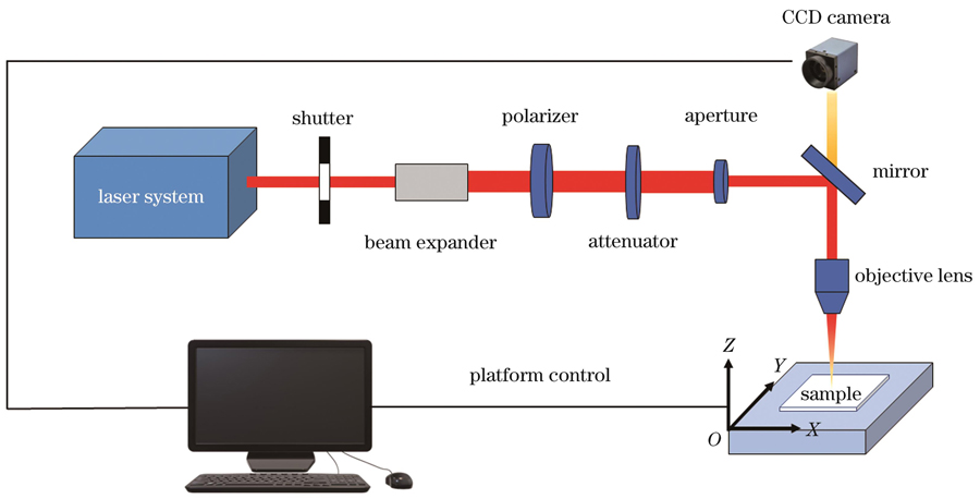
    Fig. 1. Schematic of laser processing optical path
    Schematic of stealth dicing
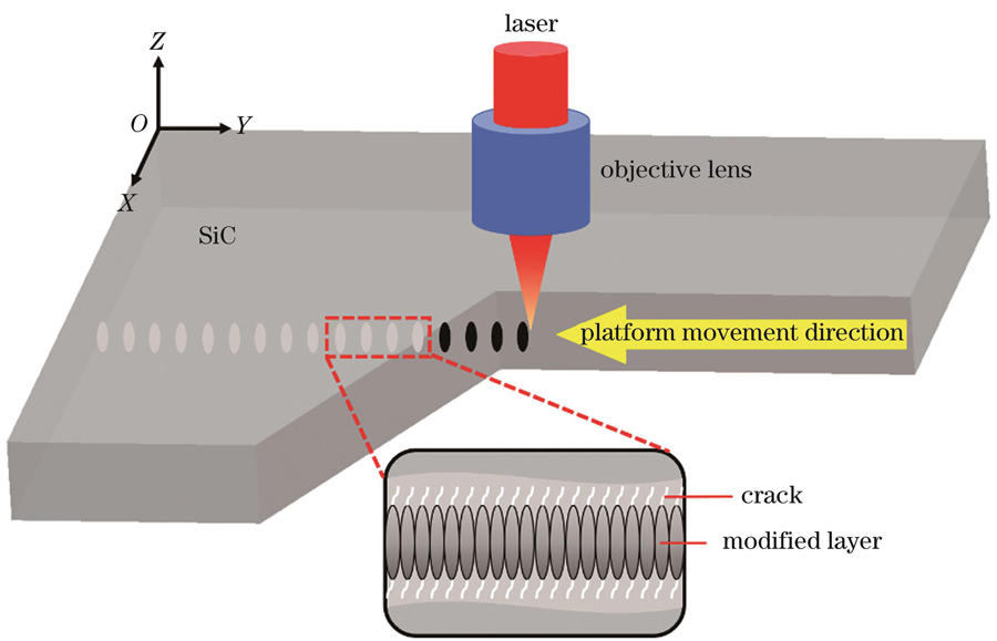
    Fig. 2. Schematic of stealth dicing
    Flow chart of laser stealth dicing. (a) Prefabricating ablation channel on bottom surface; (b) modified layers formed inside;(c) multi-modifying along step direction; (d) splitting along modified surface
    Fig. 3. Flow chart of laser stealth dicing. (a) Prefabricating ablation channel on bottom surface; (b) modified layers formed inside;(c) multi-modifying along step direction; (d) splitting along modified surface
    Schematics of internal pulse pick. (a) Pulse sequence of seed source; (b) TTL level signal; (c) picked pulses
    Fig. 4. Schematics of internal pulse pick. (a) Pulse sequence of seed source; (b) TTL level signal; (c) picked pulses
    Schematics of multi-pulse mode and burst mode pulse. (a) single pulse; (b) two sub-pulses; (c) n sub-pulses
    Fig. 5. Schematics of multi-pulse mode and burst mode pulse. (a) single pulse; (b) two sub-pulses; (c) n sub-pulses
    Influence of pulse energy on cutting effect under multi-pulse mode. (a1)-(a4) Morphologies of top surface ; (b1)-(b4) morphologies of bottom surface ; (c1)-(c3) edge chipping morphologies of top surface; (d1)-(d3) edge chipping morphologies of bottom surface; (e1)-(e3) cross-section morphologies; (f) influence of single pulse energy on kerf width; (g) influence of single pulse energy on top and bottom edge chipping sizes and cross-section roughness
    Fig. 6. Influence of pulse energy on cutting effect under multi-pulse mode. (a1)-(a4) Morphologies of top surface ; (b1)-(b4) morphologies of bottom surface ; (c1)-(c3) edge chipping morphologies of top surface; (d1)-(d3) edge chipping morphologies of bottom surface; (e1)-(e3) cross-section morphologies; (f) influence of single pulse energy on kerf width; (g) influence of single pulse energy on top and bottom edge chipping sizes and cross-section roughness
    Influence of feed distance on cutting effect under multi-pulse mode. (a1)-(a3) Morphologies of top surface; (b1)-(b3) morphologies of bottom surface; (c1)-(c3) edge chipping morphologies of top surface; (d1)-(d3) edge chipping morphologies of bottom surface; (e1)-(e3) cross-section morphologies; (f) influence of feed distance on kerf width; (g) influence of feed distance on top and bottom edge chipping sizes and cross-section roughness
    Fig. 7. Influence of feed distance on cutting effect under multi-pulse mode. (a1)-(a3) Morphologies of top surface; (b1)-(b3) morphologies of bottom surface; (c1)-(c3) edge chipping morphologies of top surface; (d1)-(d3) edge chipping morphologies of bottom surface; (e1)-(e3) cross-section morphologies; (f) influence of feed distance on kerf width; (g) influence of feed distance on top and bottom edge chipping sizes and cross-section roughness
    Influence of repetition frequency on cutting effect under multi-pulse mode. (a1)-(a4) Morphologies of top surface; (b1)-(b4) morphologies of bottom surface; (c1)-(c4) edge chipping morphologies of top surface; (d1)-(d4) edge chipping morphologies of bottom surface; (e1)-(e4) cross-section morphologies; (f) influence of repetition frequency on kerf width; (g) influence of repetition frequency on top and bottom edge chipping sizes and cross-section roughness
    Fig. 8. Influence of repetition frequency on cutting effect under multi-pulse mode. (a1)-(a4) Morphologies of top surface; (b1)-(b4) morphologies of bottom surface; (c1)-(c4) edge chipping morphologies of top surface; (d1)-(d4) edge chipping morphologies of bottom surface; (e1)-(e4) cross-section morphologies; (f) influence of repetition frequency on kerf width; (g) influence of repetition frequency on top and bottom edge chipping sizes and cross-section roughness
    Influence of pulse width on cutting effect under multi-pulse mode. (a1)-(a3) Morphologies of top surface; (b1)-(b3) morphologies of bottom surface; (c1)-(c3) edge chipping morphologies of top surface; (d1)-(d3) edge chipping morphologies of bottom surface ; (e1)-(e3) cross-section morphologies; (f) influence of pulse width on kerf width; (g) influence of pulse width on top and bottom edge chipping sizes and cross-section roughness
    Fig. 9. Influence of pulse width on cutting effect under multi-pulse mode. (a1)-(a3) Morphologies of top surface; (b1)-(b3) morphologies of bottom surface; (c1)-(c3) edge chipping morphologies of top surface; (d1)-(d3) edge chipping morphologies of bottom surface ; (e1)-(e3) cross-section morphologies; (f) influence of pulse width on kerf width; (g) influence of pulse width on top and bottom edge chipping sizes and cross-section roughness
    Influence of scanning speed on cutting effect under multi-pulse mode. (a1)-(a3) Morphologies of top surface; (b1)-(b3) morphologies of bottom surface; (c1)-(c3) edge chipping morphologies of top surface; (d1)-(d3) edge chipping morphologies of bottom surface; (e1)-(e3) cross-section morphologies; (f) influence of scanning speed on kerf width; (g) influence of scanning speed on top and bottom edge chipping sizes and cross-section roughness
    Fig. 10. Influence of scanning speed on cutting effect under multi-pulse mode. (a1)-(a3) Morphologies of top surface; (b1)-(b3) morphologies of bottom surface; (c1)-(c3) edge chipping morphologies of top surface; (d1)-(d3) edge chipping morphologies of bottom surface; (e1)-(e3) cross-section morphologies; (f) influence of scanning speed on kerf width; (g) influence of scanning speed on top and bottom edge chipping sizes and cross-section roughness
    Influence of sub-pulse number on cutting effect under burst mode. (a1)-(a4) Morphologies of top surface; (b1)-(b4) morphologies of bottom surface; (c1)-(c4) edge chipping morphologies of top surface; (d1)-(d4) edge chipping morphologies of bottom surface; (e1)-(e4) cross-section morphologies; (f) influence of sub-pulse number on kerf width; (g) influence of sub-pulse number on top and bottom edge chipping sizes and cross-section roughness
    Fig. 11. Influence of sub-pulse number on cutting effect under burst mode. (a1)-(a4) Morphologies of top surface; (b1)-(b4) morphologies of bottom surface; (c1)-(c4) edge chipping morphologies of top surface; (d1)-(d4) edge chipping morphologies of bottom surface; (e1)-(e4) cross-section morphologies; (f) influence of sub-pulse number on kerf width; (g) influence of sub-pulse number on top and bottom edge chipping sizes and cross-section roughness
    ParameterContent
    Wavelength1030 nm
    Pulse duration270 fs-10 ps
    Frequency50 kHz-20 MHz
    Maximum power80 W
    Maximum pulse energy160 μJ
    Beam qualityM2<1.3
    Beam modeTEM00 Gaussian mode
    Table 1. Main parameters of ultrafast laser
    ParameterValue
    Magnification50×
    Numerical aperture0.65
    Focal length4 mm
    Working distance10 mm
    Wavelength range480-1800 nm
    Table 2. Main parameters of objective lens
    ParameterX-axis directionY-axis directionZ-axis direction
    Maximum travel of platform200 mm600 mm100 mm
    Maximum speed800 mm/s800 mm/s200 mm/s
    Repeat positioning accuracy±1 μm±1 μm±1 μm
    Positioning accuracy±2 μm±2 μm±2 μm
    Resolution0.01 μm0.01 μm0.01 μm
    Table 3. Main parameters of movement platform
    Yunpeng Ren, Xincheng Tu, Kun He, Li Cheng, Yunxia Ye, Xudong Ren, Naifei Ren. Study of Stealth Dicing of Silicon Carbide Wafers Under Ultrafast Laser Multi‑Pulse Mode and Burst Mode[J]. Chinese Journal of Lasers, 2023, 50(20): 2002405
    Download Citation