1Key Laboratory of Terahertz Solid-State Technology, Shanghai Institute of Microsystem and Information Technology, Chinese Academy of Sciences, Shanghai 200050, China
2Center of Materials Science and Optoelectronics Engineering, University of Chinese Academy of Sciences, Beijing 100049, China
We propose and experimentally demonstrate a wideband linear polarization converter in a reflection mode operating from 2.4 to 4.2 THz with conversion efficiency of more than 80%. Our device can expand the applications to a higher frequency band. A numerical simulation is performed for this metamaterial converter, which shows a good agreement with experimental results. Importantly, a concise and intuitive calculating model is proposed for the Fabry–Pérot cavity. The theoretical results indicate that the underlying reason for the enhanced polarization conversion is the additional phase difference induced by the resonance of the meta-structure and multiple reflections within the Fabry–Pérot cavity.
Polarization of light is one of the basic properties that has been studied in various fields and applications, such as transformation optics, anomalous refraction[1], optical spin Hall effect[2,3], sub-wavelength focusing[4], and laser beam shaping[5]. Control and manipulation of light polarization states plays a fundamental role in these fields. A polarization converter can convert polarization states into another desired one with high efficiency via simple experimental configurations. Recently, metamaterials have enabled high-efficiency and broadband polarization converting, showing outstanding potential for further applications and expanding the studies of metamaterials[1,6]. Conventional polarization converters use the birefringence effects of crystals. However, these converters show obvious drawbacks, that is, bulky configuration and narrow band.
Various terahertz (THz) metasurface devices have been specifically proposed either for cross-polarization converting or linear-to-circular polarization converting[1,7,8]. Most of them are three-layered sandwich structures working in the reflection mode or transmission mode. They consist of a polyimide dielectric spacer, a grating ground, and a layer of periodic cells, such as V-shaped antennas, C-shaped antennas, or split-ring resonators[9–11]. However, almost all these designs aimed at applications in the range of frequencies from 0.5 to 1.4 THz[12–15]. This lower band of the THz region has very limited applications in polarization imaging[16–19], THz spectroscopy[20], THz quantum cascade laser systems[21], and THz photonics[22] due to its wave-like characteristics.
In this Letter, we demonstrate numerically and experimentally a metamaterial reflective polarization converter that operates with high efficiency () in the frequency band from 2.4 to 4.2 THz. Furthermore, we propose an intuitive and simple model to account for the polarization converting effect. Generally, there are two explanations for the process of polarization conversion. One is the magnetic resonances between the meta-structure layer and bottom layer, which are both metallic and form a sandwich structure together with the central insulating layer, and it can be revealed qualitatively from simulation results of the surface current loop[7]. The other one is the Fabry–Pérot (F-P) cavity model related to the propagating and truncation of the confined mode between two metallic layers, which is widely accepted by many researchers[1,23]. However, it is intricate in calculation and fails to expose the role of the metasurface layer explicitly. Our method indicates that the meta-structures have different and independent effects on two orthogonal directions, and thus they can be dealt with separately. In the following part, we explain the polarization converting process in the coordinate system, and we can see that the physics is very clear; that is, electric resonance and the F-P cavity together result in a 180° phase difference between the -polarized and -polarized components. We expect that our demonstration will expand applications of metamaterials in the THz region and simplify the design and analysis process of metamaterial-based devices.
Sign up for Chinese Optics Letters TOC. Get the latest issue of Chinese Optics Letters delivered right to you!Sign up now
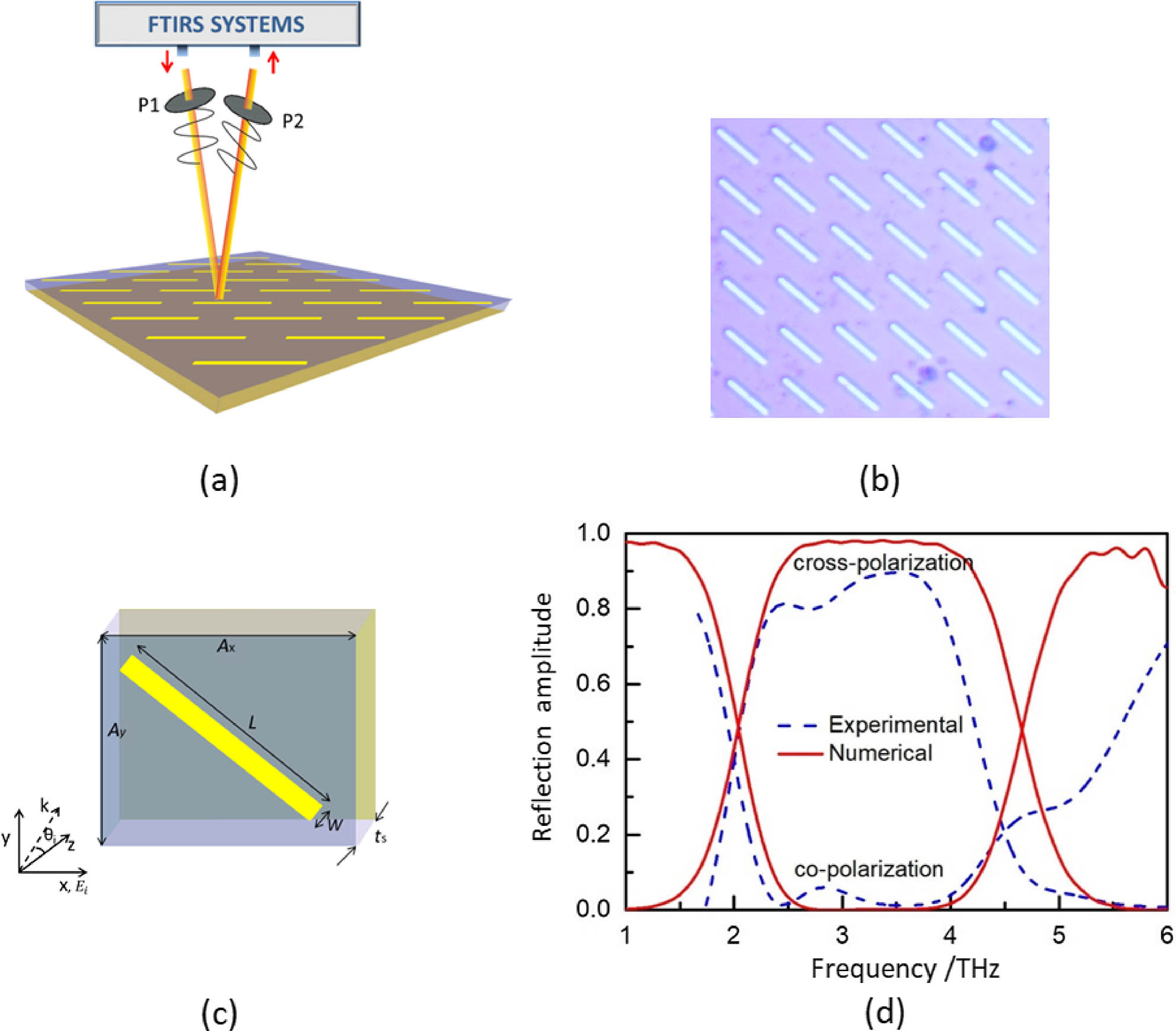
The schematic diagram of our proposed linear polarization converter is illustrated in Fig. 1(a). The converter is composed of three layers, which are cut-wire arrays, a dielectric spacer, and a ground plane acting as a mirror. The specific parameters of a unit cell are shown in Fig. 1(c), which are optimized by multiple simulations. The device was fabricated on the polyimide film by UV lithography and the lift-off process, and the microscopic image of the sample is shown in Fig. 1(b).
Figure 1.Schematic diagram and experimental results of the polarization converter in reflection. (a) Schematic diagram where p1 and p2 are wire-grid polarizers, one acting as a polarizer to produce -polarized light and the other as an analyzer to get the -polarized component of the reflected light, respectively. (b) Optical micrograph of fabricated metamaterial linear polarization converter. (c) Individual element of the high-efficiency linear polarization converter. The incident angle , and electric field is linearly polarized in the direction. All the dimensions are shown, , , , and . The periodic meta-structure units and bottom mirror are made of gold via electron beam evaporation. The dielectric spacer is polyimide film with . (d) Experimentally measured and numerically simulated co-polarized and cross-polarized reflectance, corresponding to the and directions in our experiment, respectively.
The finite-difference time-domain (FDTD) method is adopted to simulate the behavior of the device. The periodic boundary condition is applied in the and directions. The incident angle is 10° with the axis, and we found that the incident angle has little influence on the performance of our converter when it is less than 20°. The optical behavior of gold is described through dispersive permittivity, which can be approximated with a Drude model in the infrared and THz spectral region[23,24] as where , the plasma frequency , and the collision frequency . The dielectric constant of polyimide was set as .
The terahertz light in the Fourier-transform infrared spectroscopy (FTIRS), which is non-polarized originally, is -polarized by polarizer p1, and then incident on the device with a small angle (less than 10°) deviated from the vertical direction for separating the incident light and the reflected light. As shown in Fig. 1(c), the direction of meta-structures is 45° with the axis. Then, an analyzer p2 is utilized for measuring the and components of the reflected light. The polarizer and analyzer can be added into the FTIRS as additional accessories, as shown in Fig. 1(a). First of all, an Au-coated mirror, which is assumed to be a perfect reflector, is placed at the position of the converter. The and components of the reflected light are measured. Then, the converter is placed at the same position with identical experimental setups, and the reflected lights are obtained in the same way. The reflection amplitudes are the ratios of the two results, that is, the ratios of the latter results to the former results.
The experimental and simulated results are shown in Fig. 1(d). In order to evaluate the performance of our designed converter, we define reflectance of any polarization component as
The subscripts and indicate the polarization states of electromagnetic (EM) waves, while denotes incident EM waves, and denotes reflected EM waves. For instance, denotes the intensity of -polarized reflected EM waves. Then, we can define the polarization converting efficiency (PCE) as when incident light is -polarized, as in our experimental setup. The experimental results of reflectance are presented in Fig. 1(d). Between 2.4 and 4.2 THz, the reflectance or PCE is more than 80%, which means the cross-polarization light carries 80% of the incident energy, and this is much higher than for other converters[7,23]. The experimental results fit well with the simulation results, as shown in Fig. 1(d). Although the simulated results show a little wider operating band and a higher PCE, it is reasonable due to fabrication and measurements deviation. There is significant energy absorption at around 4.5 THz due to the resonance of the meta-structure. For verification, we experimentally excluded the possibility of dielectric absorption.
Generally, there are two mechanisms demonstrated previously to account for the polarization converting effect. One is magnetic resonance between meta-structure layer and bottom layer, due to current loops consisting of a resonance current in metasurface and an induced current in the ground mirror, and it is well proved qualitatively that magnetic resonance leads to an enhancement of the polarization converting effect[7]. The other one is the F-P cavity model demonstrated in Refs. [1,23]. But, both are presented in a complex way and fail to give a clear physical image. Here, we present an explicit method to account for the polarization converting effect with experimental and numerical evidences.
First of all, we consider all the polarization components and physical effects in the coordinate system that rotates about the axis 45° from the coordinate system [see Fig. 2(a)]. In the new coordinate system, we can deal with -polarized and -polarized components separately in the processes of reflection, transmission, and electric resonance. The final total reflection or transmission can be obtained by combining the two components. The independence will be proved numerically and experimentally in the following. When the incident light is -polarized, it can be written in the coordinate system as
Figure 2.(a) Schematic diagram of coordinate system and the single metasurface layer. (b) Reflection and transmission coefficients extracted from the simulation of a single metasurface layer, in the considered frequency region. (c) The phase of transmission , which mainly contributes to polarization conversion. The other phases are zeros. (d) The schematic diagram of the F-P-like cavity model for multiple reflections. (e) Theoretical phases with and components, which are shown in reflection mode results from the equality of magnitudes of and components. (f) Theoretical reflection and transmission amplitudes of cross-polarization and co-polarization.
Next, we extract reflection and transmission coefficients of the single metasurface layer (the cut-wire layer) from simulations, as shown in Fig. 2(b). These , , , and represent the magnitudes of the reflection coefficients for u-to-u, u-to-v, v-to-v, and v-to-u, respectively; , , , and are the corresponding phases. Similarly, , , , and represent the magnitudes of the transmission coefficients for u-to-u, u-to-v, v-to-v, and v-to-u, respectively; , , , and are the corresponding phases. We can find in Fig. 2(b) that , and the others have different values due to the electric resonance of the meta-structure. One thing we need to point out is that does not vanish, as shown in Fig. 2(c), so a phase should be added to the EM wave when it travels through the meta-structure layer. As we have mentioned, the independence of the - and -polarization components makes the analysis and calculation easier and presents a very clear physical image.
Then, we obtain total - and -component reflection by adding multiple reflections. The results are geometric series. The -component of the total reflected field can be calculated as
The sum can be obtained when ,
Similarly, the component can be obtained, noting that vanishes:
The reflection and transmission coefficients in the above functions have been acquired from simulation results of a single metasurface layer (the cut-wire layer).
Finally, we obtained the results that the and components have a nearly 180° phase difference within 2.4–4.2 THz, as shown in Fig. 2(e) on the blue line, but the magnitudes are the same and are not represented due to the mirror reflecting almost 100%. Thus, the and components can be combined into a linearly polarized light whose direction is 45° to the axis. If we present it in the coordinates, the cross-polarization (-polarization) and co-polarization (-polarization) reflectance can be obtained, as shown in Fig. 2(f). The theoretical results are in agreement with the experimental and simulated results, which indicates that our proposed calculating method is workable, and the F-P-like cavity model plays a main role in the polarization converting process.
In conclusion, we demonstrate a high-efficiency and wideband polarization converter in the reflection mode to convert an -polarized THz wave to a -polarized wave. The operating range of frequency is from 2.4 to 4.2 THz, and the cross-polarized THz wave carries more than 80% of the incident energy. We expect applications in THz photonics, where previously demonstrated converters operating in the frequency range from 0.6 to 1.4 THz cannot be applied. Furthermore, we proposed a more intuitive and essential method based on the F-P-like cavity model to account for this linear polarization converter. Thus, the essence of the polarization converting process can highlight that the transmission phase of the -polarized component and multiple reflections in the F-P-like cavity play fundamental roles. The inconformity of our theoretical results may be caused by the magnetic resonance mentioned in some articles, but it does not have a significant contribution.
References
[1] N. K. Grady, J. E. Heyes, D. R. Chowdhury, Y. Zeng, M. T. Reiten, A. K. Azad, A. J. Taylor, D. A. R. Dalvit, H. T. Chen. Science, 123, 5399(2013).