
Zhaoli Li, Yanlei Zuo, Xiaoming Zeng, Zhaohui Wu, Xiaodong Wang, Xiao Wang, Jie Mu, Bilong Hu. Ultraintense few-cycle infrared laser generation by fast-extending plasma grating[J]. Matter and Radiation at Extremes, 2023, 8(1): 014401
- Matter and Radiation at Extremes
- Vol. 8, Issue 1, 014401 (2023)
Abstract
I. INTRODUCTION
The generation of infrared laser pulses (IRLPs) that are both ultrashort and ultraintense has developed greatly in recent years, thereby opening up new areas of scientific research. Intense single-cycle IRLPs can isolate electron dynamics in strong-field interactions, which makes them very useful for investigating ultrafast phenomena in gases and solids. Applications include advanced electron and proton acceleration,1 high-harmonic and isolated attosecond generation,2–5 infrared supercontinuum generation,6,7 lattice displacement control,8 subfemtosecond control and metrology of bound-electron dynamics in atoms,9 and time-resolved imaging of molecular structures.10 Currently, there are several means of generating high-power picosecond-to-nanosecond IRLPs, including using a Fe:ZnSe/Ho:YAG/Ho:YLF-based solid-state laser,11,12 a KTA/ZGP-based optical-parametric-amplification laser,13–15 difference-frequency generation, optical rectification, a CO2 laser system,16 and the main means of generating high-energy femtosecond IRLPs: optical parametric chirped pulse amplification (OPCPA). However, a lack of a nonlinear crystal with large aperture and high energy conversion efficiency and a matching high-energy pump source means that the development of OPCPA in the mid- to far-infrared region is far behind that in the visible to near-infrared region. Other methods for generating femtosecond IRLPs—e.g., optical rectification,17–19 four-wave mixing,20–22 difference-frequency generation,23,24 photon deceleration,25 and backward Raman scattering26—can produce only nanojoule to microjoule output energy with very low efficiency, making them uneconomical for strong-field experiments. The wavelength and output energy of IRLPs generated by OPCPA are limited, and the efficiencies by other methods are too low, therefore there is a need for a suitable method for generating ultrashort ultraintense IRLPs with both high efficiency and a broadband wavelength range.
In this paper, we propose a method for producing an ultraintense few-cycle IRLP by directly compressing a long IRLP. By injecting a long-duration (picosecond to nanosecond) IRLP into a rapidly counterextending plasma grating, the former is reflected by the latter. Because the boundary of the plasma grating is rapidly counterextending in the opposite direction to that of the incident pulse, the reflected pulse is compressed, thus an ultrashort ultraintense reflected laser pulse can be generated; we call this method “fast-extending plasma-grating compression” (FEPGC). The rapidly extending plasma grating is produced by a counterpropagating strong laser pulse ionizing a density-modulated gas medium, turning it into a plasma grating, the boundary of which extends rapidly following the ionizing pulse. Because of the large refractive-index different between the plasma and the gas, the incident IRLP passes through the gas grating but is highly reflected by the plasma grating. In particular, if the wavelength of the plasma grating satisfies the Bragg condition, then the incident pulse can be totally reflected. Unlike with traditional methods, there is no damage limitation with a plasma, making it a possible means of generating relativistically intense few-cycle IRLPs. FEPGC has been proposed for generating exawatt laser power in the visible to near-infrared region,27 but we find it extremely useful to apply this method to the mid- to far-infrared region. First, the density grating can only be created optically in the visible to near-infrared region, whereas in the mid- to far-infrared region it can be produced optically, acoustically, or mechanically (see the following discussion), which makes FEPGC much cheaper and easier to realize in the laboratory. Second, although there are some methods for producing ultraintense femtosecond laser pulses in the visible to near-infrared region (e.g., OPCPA), an effective method for producing ultraintense femtosecond pulses is still lacking for the mid- to far-infrared region, and so FEPGC is particularly interesting for that region.
The remainder of this paper is organized as follows. In Sec. II, we present the basic theory of the compression method. In Sec. III, we present simulation results regarding the effectiveness and constraints of FEPGC. Finally, we present conclusions in Sec. IV.
II. BASIC THEORY
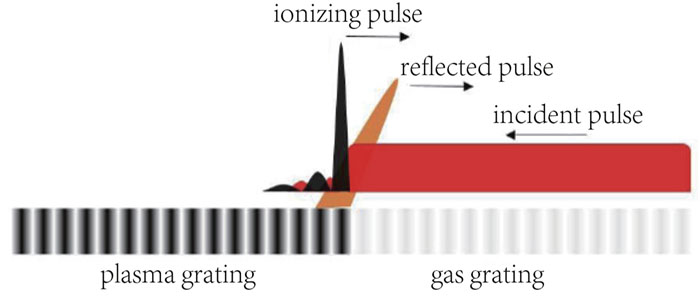
As shown schematically in Fig. 1, an IRLP propagates into a rarefied gas with a sinusoidal density profile, and another counterpropagating ionizing laser pulse with arbitrary wavelength ionizes the gas, turning it into a plasma grating. If the period of the plasma grating is close to half the wavelength of the IRLP, then the portion of the IRLP that meets the front of the plasma grating is totally reflected. In this scheme, the front of the plasma grating sweeps the IRLP from the front edge to the tail edge with relative velocity 2c, thus different portions of the IRLP that are reflected at different times are spatially superimposed when reflected; the reflected light accumulates behind the front of the plasma grating, and an ultraintense few-cycle IRLP is generated. The ionizing laser pulse is polarized orthogonally to the IRLP and so does not interact with it.
![]()
Figure 1.Schematic of fast-extending plasma-grating compression (FEPGC) amplification scheme.
Suppose that the plasma density is ne = n0(1 + Δ cos(kpz)), where n0 is the background plasma density, Δ is the density modulation amplitude, and λp = 2π/kp is the grating period. Unlike the usual Bragg grating, the boundary of the plasma grating is extending rapidly toward the incident IRLP. Assuming that the ionization front is located at (0,0) initially and then extends to (x0, t0) with velocity vfr, the vector potential Ar of the reflected pulse at point x0 is determined by the wave equation
The electric field of the reflected pulse is
Assuming that the incident IRLP has constant transverse electric field Ei = E0 cos(k0x + ω0t), where k0 and ω0 are respectively the wavenumber and frequency of the incident pulse, the polarization current can be written as
Inserting Eq. (4) into Eq. (3), we obtain
From Eq. (5), when the wavenumber of the plasma density modulation equals the wavenumber of the incident pulse plus the incident pulse frequency divided by the front velocity, i.e.,
If the velocity of the ionizing front is approximately equal to the group velocity of the ionizing pulse in the plasma, then the wavenumber matching condition can be written as
If Eq. (8) is satisfied, then the electric field of the reflected wave grows linearly with the interaction distance, as shown by Eq. (7). Different parts of the incident pulse superimpose when reflected, thus the reflected pulse is compressed and its amplitude increases, and because the grating has high reflectivity, the conversion efficiency is high.
The whole reflection and compression process can also be regarded as a “forced” stimulated Brillouin scattering (SBS) process, except that here the ion acoustic wave is pregenerated and activated by the ionizing pulse instead of being generated by the beatwave of the pump (incident pulse) and the seed (reflected pulse). So in this case, the ion acoustic wave has large amplitude at the outset, and the interaction enters the nonlinear region directly at the outset. In this nonlinear region, the front of the seed receives energy from the pump and the back of the seed gives energy to the pump, so the seed width gradually decreases. Then, by using the three-wave coupling model and assuming that the ion acoustic wave amplitude δne/n0 ≡ Δ is constant, we obtain the maximum amplitude of the reflected pulse as27
The key factor in this compression scheme is producing a modulated gas density. One method for doing so is to use a gas acoustic wave and gas Brillouin scattering.27 By transmitting a nanosecond laser pulse into gas, the former can be Brillouin scattered because of the gas electrostatic effect, and the steady-state amplitude of the gas acoustic wave is determined by
The second method uses a laser interference pattern to sculpt grooves in a gas medium. As done by Zhang et al.,30 sending two moderate-intensity laser pulses into a gas generates an interference pattern that ionizes part of the gas into a plasma, generating an alternating plasma and gas grating. After 40–80 ps, the plasma diffuses and the plasma grating is smoothed out, leaving behind the gas grating. By using another strong laser pulse to ionize this gas grating, a rapidly extending plasma grating can be generated. Taking the wavelength of the interfering pulses as λint, their crossing angle θ should satisfy λint/(2 sin(θ/2)) = 2π/kp so that the Bragg condition is satisfied. Note that unlike in other schemes where a grating or mirror moves with some velocity, in this scheme the grating itself is static but its boundary is extending.
Another way is to use a modulated ionizing laser intensity in the focal region. For example, in the case of corrugated plasma guiding structures,31 an axicon lens was used to line-focus an axially modulated laser pulse onto a gas cluster. Because of the axial modulation pattern, the laser intensity rises and falls repeatedly along the focal line, producing a grating-like plasma–gas oscillation. Layer et al.31 used this technique to produce stable plasma waveguides with short 35-μm axial modulation periods. Also, a cylindrical lens has been used to focus a machining beam, with the spatial intensity profile of the machining beam programmed by an amplitude modulator array (a mask) to produce a periodic plasma waveguide.32 A drawback of these methods is that the output intensity is limited by the ionizing threshold of the residual gas in the plasma region, but this can be overcome by letting the plasma diffuse and smooth out and then ionizing the gas structure again, as in the second method.
III. SIMULATION RESULTS
In this section, we present particle-in-cell (PIC) simulation results to confirm the ability of the FEPGC method to compress the IRLP. The fully kinetic PIC code EPOCH33 was used to run 1D simulation of FEPGC for a sinusoidal H2 gas of density ne/ncr = 0.02 + 0.01 sin(2πx/λp), where ncr is the critical density of the infrared laser. In the simulation, we found that the best results were achieved with λp = 5.02 μm, which is slightly smaller than the theoretical value λp = 5.025 μm given by Eq. (8). An IRLP of wavelength 10 μm and intensity I0 = 3 × 10¹³ W/cm2 was injected from the right boundary of the simulation box. When the IRLP moved to the left boundary of the box, an ionizing pulse was injected from the left boundary. The 1D simulation box was 9 mm long and contained 20 cells per wavelength and 16 particles per cell, and the total simulation time was 60 ps. The IRLP had a flat profile with infinite duration. The choice of ionizing pulse is arbitrary to a large extent, the only requirement being that the gas is totally ionized in a short time. In this simulation, we used an ionizing pulse with a six-rank super-Gaussian profile, a duration of 100 fs (FWHM), a wavelength of 1 μm, and an intensity of I0 = 1 × 10¹⁵ W/cm2. The IRLP and the ionizing pulse were cross polarized so that they could be separated in the post-process.
Figure 2 shows the compression of the IRLP at different times during the simulation. In the beginning, the incident IRLP propagates freely toward the left boundary of the simulation box. Because of its low intensity, it cannot ionize the gas grating, thus only a small portion of the incident pulse is refracted by the gas grating. When the IRLP reaches the left boundary, the ionizing pulse enters the simulation box from the left boundary, turning the gas grating into a plasma grating. Because of the much larger refractive-index difference of the plasma grating compared to the gas grating, a large part of the incident IRLP is reflected from the front of the plasma grating and moves together with the ionizing pulse from the left boundary to the right boundary, therefore the reflected pulse is compressed. After 30 ps of interaction, the maximum intensity of the reflected pulse reaches 8.56 × 10¹⁵ W/cm2, the pulse duration is compressed to 60 fs (FWHM), and the energy transfer ratio is 63.7% (the reflected pulse has a multi-peak structure, and if only the first peak is accounted for, then the efficiency is ∼40%).
![]()
Figure 2.10-
The variations of the peak intensity and FWHM duration of the reflected pulse with simulation time are shown in Fig. 3. The solid lines are for I0 = 3 × 10¹³ W/cm2 and Δ = 50%; the dashed lines are for I0 = 2 × 10¹³ W/cm2 and Δ = 50%; the dotted lines are for I0 = 3 × 10¹³ W/cm2 and Δ = 40%; the dash-dotted lines are for I0 = 3 × 10¹³ W/cm2 and Δ = 60%. As can be seen, for I0 = 3 × 10¹³ W/cm2 and Δ = 50%, the peak intensity reaches its maximum of 1.046 × 10¹⁶ W/cm2 at t = 57 ps, after which it decreases and the duration increases slightly. This is attributed to relativistic mass increase and gas ionization. When the incident IRLP intensity or the gas density modulation is lower, the intensity of the reflected pulse is lower and the duration is longer, but with sufficient simulation time, they still reach comparable maximum/minimum values.
![]()
Figure 3.Peak intensity and FWHM duration of reflected pulse with different simulation times. Solid lines:
To assess the robustness of our scheme, we changed the grating period from 5 to 5.05 μm, and the results are shown in Fig. 4. As can be seen, there is a minimum region around the maximum point, but outside this region the peak intensity remains high and the duration remains low. Changing the grating period disrupts the matching condition Eq. (8) so that the reflected light is not superimposed coherently, but this effect is weak with a large grating period range. With increasing gas density, the grating period that maximizes the peak output intensity increases slightly, which fits the theoretical prediction Eq. (8) very well. When the gas density is high, the grating period range in which the peak output intensity remains high becomes narrower, thus one needs to balance short plasma length and stable performance.
![]()
Figure 4.Peak intensity and duration of reflected pulse at
In the second half of the interaction, the ionizing pulse is actually depleted, and the gas ionization is produced by the reflected pulse itself. Thus, in some circumstances, this process can be a self-compression process, for example by placing a totally reflecting mirror behind the gas. We also found that when we increased the intensity or width of the ionizing pulse, the width of the reflected pulse increased slightly, indicating a small contribution of gas ionization to the pulse compression.
The spectrum of the reflected pulse at t = 60 ps is shown in Fig. 5. As can be seen, the reflected pulse has a broad bandwidth ranging from 0.5ω0 to 1.5ω0, consistent with the temporal compression of the IRLP. The spectrum has several subpeaks at ω/ω0 = 1 ± 0.15n, n = 1, 2, …. Recalling that the plasma frequency in the simulation was ωp = 0.14ω0, these subpeaks seem to be the Stokes and anti-Stokes components of Raman scattering. There is also a component close to ω/ω0 = 3.26, and this is attributed to the frequency up-conversion induced by the counterpropagating ionization front.34–36 If we assume that the ionizing-front density gradient is36Lv = 50 fs (FWHM of the reflected pulse), then the up-conversion frequency is
![]()
Figure 5.Spectrum of reflected pulse at
To show how to use the second plasma-grating generation method to compress the laser pulse, we ran a 2D EPOCH simulation. The simulation box was 1.5 mm long and 0.6 mm high with a 10% vacuum region on the left and right boundary, i.e., 1.2-mm-long H2 gas in the center. The gas density was set to 0.1nc because the gas density modulation is less than 50% by the second method. First, two interfering laser pulses with a wavelength of 10 μm, a width of 8 ps, a radius of 200 μm (tenth-order super-Gaussian shape focused on the center of the simulation box; see the help documentation of the EPOCH software for more details), and an intensity of 3 × 10¹³ W/cm2 entered the simulation region with a crossing angle of 5° to produce a grating period of 5.02 μm. After the interfering pulses had just left the simulation box (t = 13.33 ps), the gas and plasma exhibited strong density modulations, as shown in Figs. 6(a) and 6(b). The simulation box was then left to evolve freely until t = 40 ps. As shown in Figs. 6(c) and 6(d), the gas still had a strong density modulation, but that of the plasma had smeared out. Then, an IRLP [10-μm wavelength, 8-ps width, 100-μm radius (Gaussian shape focused on midpoint of right boundary), and an intensity of 3 × 10¹³ W/cm2] entered from the left boundary. When the front of the IRLP reached the right boundary, an ionizing pulse [1-μm wavelength, 100-fs width, 200-μm radius (tenth-order super-Gaussian shape focused on midpoint of right boundary), and an intensity of 1 × 10¹⁵ W/cm2] entered the simulation box from the right boundary. The intensity of the y-polarized electric field (the incident IRLP plus the reflected pulse) when the IRLP just reached the right boundary and when the ionizing pulse just reached the left boundary is shown in Fig. 7. After just 1.2 mm of compression, the IRLP was converted to a reflected pulse with a peak intensity of 2.24 × 10¹⁴ W/cm2 and a width of 833 fs, comparable with the 1D results and showing the effectiveness of FEPGC.
![]()
Figure 6.Gas density and plasma density at (a) and (b)
![]()
Figure 7.
IV. CONCLUSION
We have proposed the FEPGC method for compressing an IRLP of arbitrary wavelength. By this method, a picosecond laser pulse can be compressed into one of tens of femtoseconds with an energy transfer ratio exceeding 60%. This proposal has the potential to replace the compression grating in OPCPA, providing new laser-compression avenues that can increase the power density of the IRLP to ∼1016 W/cm2 before being focused and decrease the width of the IRLP to two or three cycles, far beyond what existing technology can achieve.
ACKNOWLEDGMENTS
Acknowledgment. This work was supported by the Innovation and Development Foundation of China Academy of Engineering Physics (Grant No. CX20200022), the National Key Program for S&T Research and Development (Grant No. 2018YFA0404804) and the National Natural Science Foundation of China (Grant No. 11875240).
References
[1] M.Babzien, N. P.Dover, G. I.Dudnikova, M.Ispiriyan, Z.Najmudin, C. A. J.Palmer, I.Pogorelsky, M. N.Polyanskiy, J.Schreiber, P.Shkolnikov, V.Yakimenko. Monoenergetic proton beams accelerated by a radiation pressure driven shock. Phys. Rev. Lett., 106, 014801(2011).
[2] S.Ali?auskas, G.Andriukaitis, P.Arpin, T.Bal?iunas, A.Baltu?ka, A.Becker, S.Brown, M.-C.Chen, A.Gaeta, C.Hernández-García, A.Jaron-Becker, H. C.Kapteyn, O. D.Mücke, M. M.Murnane, L.Plaja, D.Popmintchev, T.Popmintchev, A.Pugzlys, S. E.Schrauth, B.Shim. Bright coherent ultrahigh harmonics in the keV x-ray regime from mid-infrared femtosecond lasers. Science, 336, 1287(2012).
[3] J.Biegert, S. L.Cousin, M.Hemmer, F.Silva, S. M.Teichmann. Spatiotemporal isolation of attosecond soft X-ray pulses in the water window. Nat. Commun., 6, 6611(2015).
[4] A.Becker, C.Hernández-García, A.Jaron-Becker, H. C.Kapteyn, M. M.Murnane, J. A.Pérez-Hernández, L.Plaja, T.Popmintchev. Zeptosecond high harmonic keV x-ray waveforms driven by midinfrared laser pulses. Phys. Rev. Lett., 111, 033002(2013).
[5] S.Ali?auskas, A.Baltu?ka, T.Elsaesser, M.Holtz, V.Juvé, S.Ku, A.Pug?lys, J.Weisshaupt, M.Woerner. High-brightness table-top hard X-ray source driven by sub-100-femtosecond mid-infrared pulses. Nat. Photonics, 8, 927-930(2014).
[6] J.Pigeon. Generation of ultra-broadband, mid-IR radiation in GaAs pumped by picosecond 10
[7] S.Ali?auskas, G.Andriukaitis, A.Baltu?ka, A. B.Fedotov, T.Fl?ry, A. V.Mitrofanov, A.Pug?lys, D. A.Sidorov-Biryukov, E. A.Stepanov, A. A.Voronin, A. M.Zheltikov. Mid-infrared laser filaments in the atmosphere. Sci. Rep., 5, 8368(2015).
[8] A.Cavalleri, M.F?rst, S.Kaiser, C.Manzoni, R.Merlin, Y.Tokura, Y.Tomioka. Nonlinear phononics as an ultrafast route to lattice control. Nat. Phys., 7, 854-856(2011).
[9] M.Garg, E.Goulielmakis, M. T.Hassan, N.Karpowicz, F.Krausz, T. T.Luu, A.Moulet, V.Pervak, O.Raskazovskaya, A. M.Zheltikov, P.Zhokhov. Optical attosecond pulses and tracking the nonlinear response of bound electrons. Nature, 530, 66-70(2016).
[10] P.Agostini, C. I.Blaga, A. D.DiChiara, L. F.DiMauro, C. D.Lin, T. A.Miller, E.Sistrunk, J.Xu, K.Zhang. Imaging ultrafast molecular dynamics with laser-induced electron diffraction. Nature, 483, 194-197(2012).
[11] P. A.Budni, R. T.Castro, E. P.Chicklis, E. J.Gustafson, C. R.Ibach, S. D.Setzler. 50-mJ,
[12] M.Bock, T.Elsaesser, U.Griebner, D.Ueberschaer, L.von Grafenstein. Ho:YLF chirped pulse amplification at kilohertz repetition rates – 4.3 ps pulses at 2
[13] J. S.Li, J. L.Wang, P.Wang, D. G.Xu, J. Q.Yao, K.Zhong. High-pulse-energy high-efficiency mid-infrared generation based on KTA optical parametric oscillator. Appl. Phys. B, 100, 749-753(2010).
[14] H.Fonnum, M. W.Haakestad, E.Lippert. Mid-infrared source with 0.2 J pulse energy based on nonlinear conversion of Q-switched pulses in ZnGeP2. Opt. Express, 22, 8556-8564(2014).
[15] M.Gong, J.Liu, Q.Liu, Z.Zhang. A high energy 3.75
[16] D.Haberberger, C.Joshi, S.Tochitsky. Fifteen terawatt picosecond CO2 laser system. Opt. Express, 18, 17865(2010).
[17] D.Brida, G.Cerullo, R.Huber, F.Junginger, A.Leitenstorfer, M.Marangoni, B.Mayer, O.Schubert, A.Sell. Single-cycle multiterahertz transients with peak fields above 10 MV/cm. Opt. Lett., 35, 2645-2647(2010).
[18] D. R.Austin, M.Baudisch, J.Biegert, A.Couairon, D.Faccio, M.Hemmer, F.Silva, A.Thai. Multi-octave supercontinuum generation from mid-infrared filamentation in a bulk crystal. Nat. Commun., 3, 807(2012).
[19] C.Gong, C.Joshi, J. J.Pigeon, S. Ya.Tochitsky. Supercontinuum generation from 2 to 20
[20] T.Fuji, K.Ishii, Y.Nomura, H.Shirai, N.Tsurumachi, A. A.Voronin, A. M.Zheltikov. Phase-stable sub-cycle mid-infrared conical emission from filamentation in gases. Opt. Express, 20, 24741-24747(2012).
[21] T.Fuji, Y.Nomura, H.Shirai. Generation and characterization of phase-stable sub-single-cycle pulses at 3000 cm−1. IEEE J. Sel. Top. Quantum Electron., 21, 8700612(2015).
[22] C.Joshi, J. J.Pigeon, S. Ya.Tochitsky, E. C.Welch. Measurements of the nonlinear refractive index of air, N2, and O2 at 10
[23] A.Apolonski, J.Biegert, E.Fill, N.Karpowicz, F.Krausz, N.Lilienfein, T.Paasch-Colberg, V.Pervak, M.Pescher, O.Pronin, I.Pupeza, D.Sánchez, W.Schweinberger, M.Seidel, Z.Wei, J.Zhang, I.Znakovskaya. High-power sub-two-cycle mid-infrared pulses at 100 MHz repetition rate. Nat. Photonics, 9, 721-724(2015).
[24] N.Flemens, K.-H.Hong, F. X.K?rtner, P.Krogen, H.Liang, J.Moses, H.Suchowski. Generation and multi-octave shaping of mid-infrared intense single-cycle pulses. Nat. Photonics, 11, 222-226(2017).
[25] Z.Cheng, H.-H.Chu, Y.He, J.Hua, C.Joshi, F.Li, S.Liu, W.Lu, Y.Ma, W. B.Mori, Z.Nie, X.Ning, C.-H.Pai, Q.Su, Y.Wan, J.Wang, Y.Wu, C.Zhang, J.Zhang. Relativistic single-cycle tunable infrared pulses generated from a tailored plasma density structure. Nat. Photonics, 12, 489-494(2018).
[26] D. F.Gordon, B.Hafizi, L. A.Johnson, J. P.Palastro. Backward Raman amplification in the long-wavelength infrared. Phys. Plasmas, 24, 033107(2017).
[27] Y.Dai, B.Hu, Z.Li, J.Mu, J.Su, X.Wang, X.Wang, Z.Wu, X.Zeng, Z.Zhang, Q.Zhu, Y.Zuo. Laser compression via fast-extending plasma gratings. Matter Radiat. Extremes, 7, 064402(2022).
[28] F.Quéré, C.Thaury. High-order harmonic and attosecond pulse generation on plasma mirrors: Basic mechanisms. J. Phys. B: At., Mol. Opt. Phys., 43, 213001(2010).
[29] A. A.Andreev, C.Riconda, V. T.Tikhonchuk, S.Weber. Short light pulse amplification and compression by stimulated Brillouin scattering in plasmas in the strong coupling regime. Phys. Plasmas, 13, 053110(2006).
[30] C.-K.Huang, C.Joshi, K. A.Marsh, Z.Nie, M.Sinclair, Y.Wu, C.Zhang. Ionization induced plasma grating and its applications in strong-field ionization measurements. Plasma Phys. Controlled Fusion, 63, 095011(2021).
[31] T. M.Antonsen, Y. H.Chen, B. D.Layer, Y.Leng, H. M.Milchberg, S.Varma, A.York. Ultrahigh-intensity optical slow-wave structure. Phys. Rev. Lett., 99, 035001(2007).
[32] S.-Y.Chen, C.-C.Kuo, K.-H.Lee, J.-Y.Lin, M.-W.Lin, C.-H.Pai, J.Wang. Ultrahigh-intensity optical slow-wave structure. Phys. Rev. Lett., 98, 033901(2007).
[33] T. D.Arber, A. R.Bell, K.Bennett, C. S.Brady, R. G.Evans, P.Gillies, A.Lawrence-Douglas, M. G.Ramsay, C. P.Ridgers, H.Schmitz, N. J.Sircombe. Contemporary particle-in-cell approach to laser-plasma modelling. Plasma Phys. Controlled Fusion, 57, 113001(2015).
[34] W. B.Mori. Generation of tunable radiation using an underdense ionization front. Phys. Rev. A, 44, 5118(1991).
[35] R. P. Brogle, C.Joshi, W. B.Mori, R. L.Savage. Frequency upshifting and pulse compression via underdense relativistic ionization fronts. IEEE Trans. Plasma Sci., 21, 5(1993).
[36] J. T.Mendonca, L.Oliveria e Silva. Photon acceleration in superluminous and accelerated ionization fronts. IEEE Trans. Plasma Sci., 24, 316(1996).


Set citation alerts for the article
Please enter your email address

© Copyright 2018-2021 | Chinese Laser Press. All Rights Reserved 沪ICP备15018463号-20